Hand-Crank Flashlight Made From a Micro Servo – No Batteries Needed!
by CrazyScience in Circuits > Electronics
377 Views, 3 Favorites, 0 Comments
Hand-Crank Flashlight Made From a Micro Servo – No Batteries Needed!
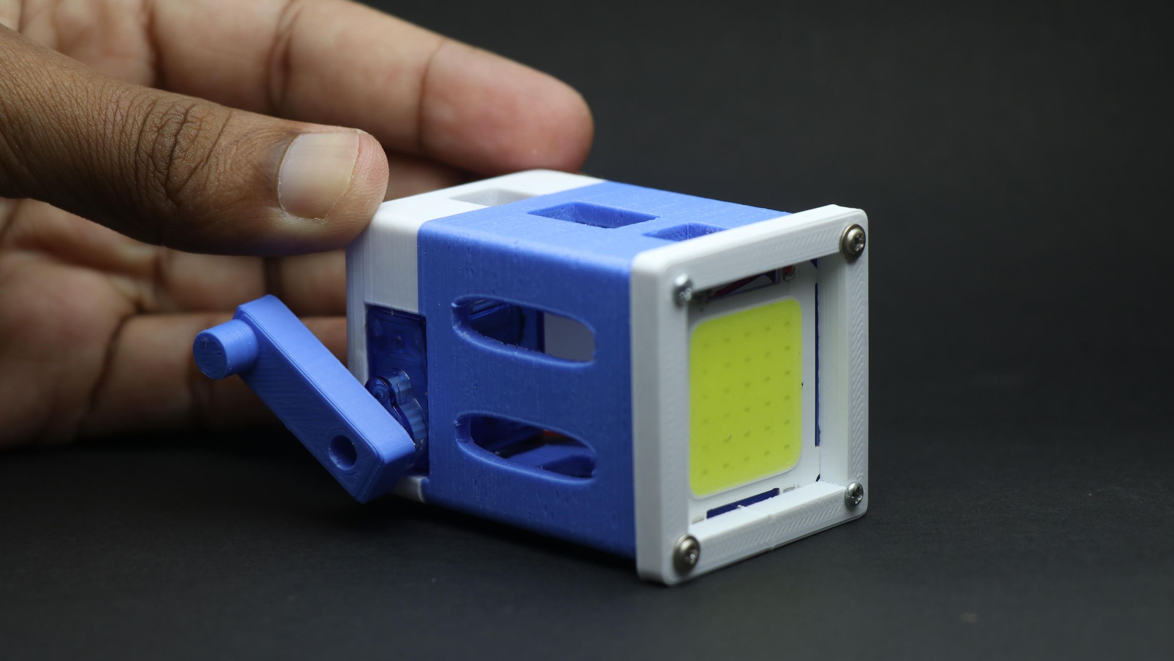
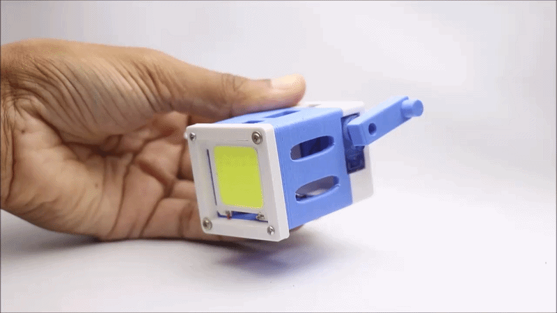
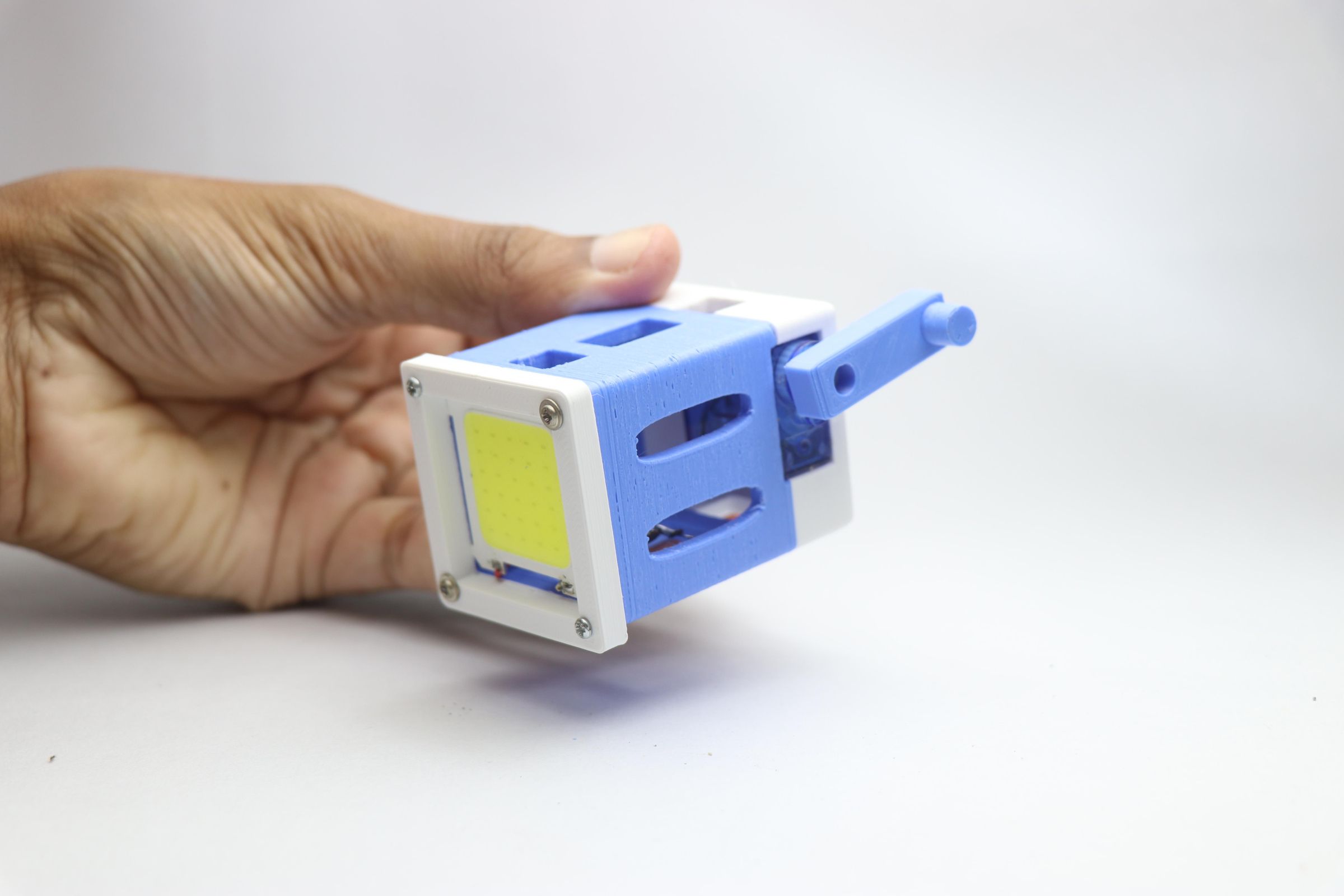
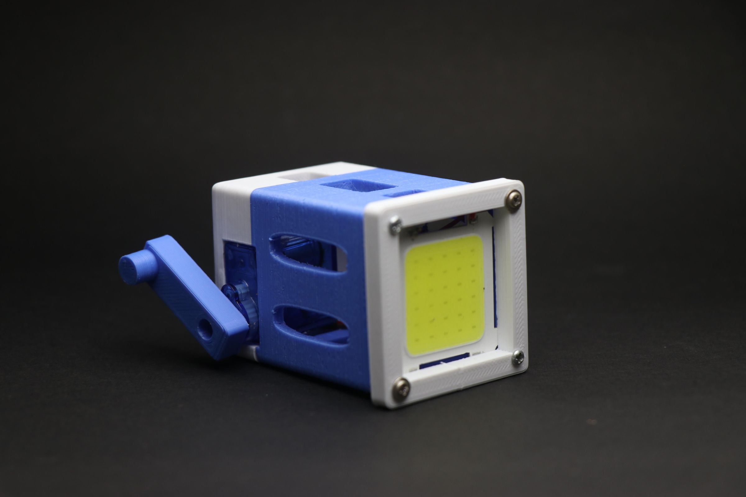
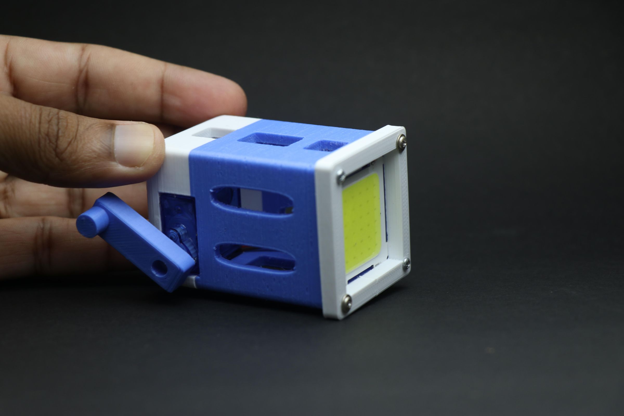
Hello friends! In this Instructable, I'll show you how to make a hand-crank powered flashlight that runs without a battery, how cool is that?
And the best part is you can build this yourself and say goodbye to conventional battery-powered flashlights.
The idea behind this battery-less torch
There were a few reasons that pushed me to build this, and I want to tell the main ones, because honestly, this project turned out to be the perfect excuse to get building!
Imagine you're out on a hike with friends most conventional torches come loaded with extra features, while DIY builds like this one keep things simple.
But here's the thing — those extra features don't really matter in a critical situation.
Say you're using a regular torch continuously on an average it lasts less than an hour, and recharging takes about 2 hours.
Now imagine yourself on a hike... where exactly are you supposed to find time (or a power outlet) to recharge? That's reason number one.
Reason number two: think about what it means to carry a device that doesn't depend on stored battery energy at all, but instead runs entirely on your energy.
No charging, no waiting, no dead battery at the worst possible moment.
I needed to fix this(important but not too important) issueand built this lightweight, 3D-printed, hand-powered flashlight (or torchlight)
It uses a small electrolytic capacitor to store the energy generated by cranking a small motor, which then powers the flashlight. As long as you keep cranking, the light keeps going — it simply never runs out.
Made from 3d printed parts the spares never run out too! on a hard hike and crashed this torch? No worries you can build it again.
This is light in weight and looks adorable too, so what is your excuse to build this battery-less flashlight?
Supplies
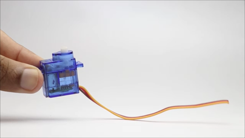
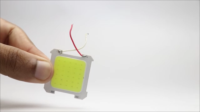
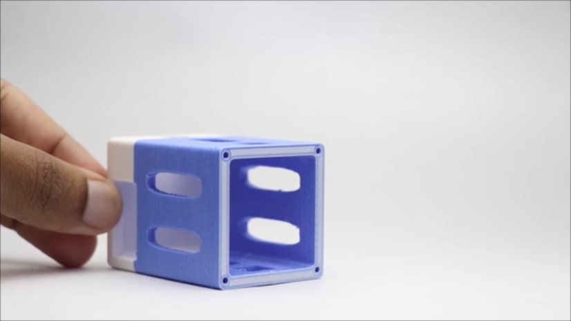
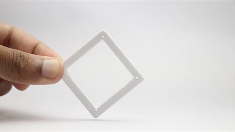
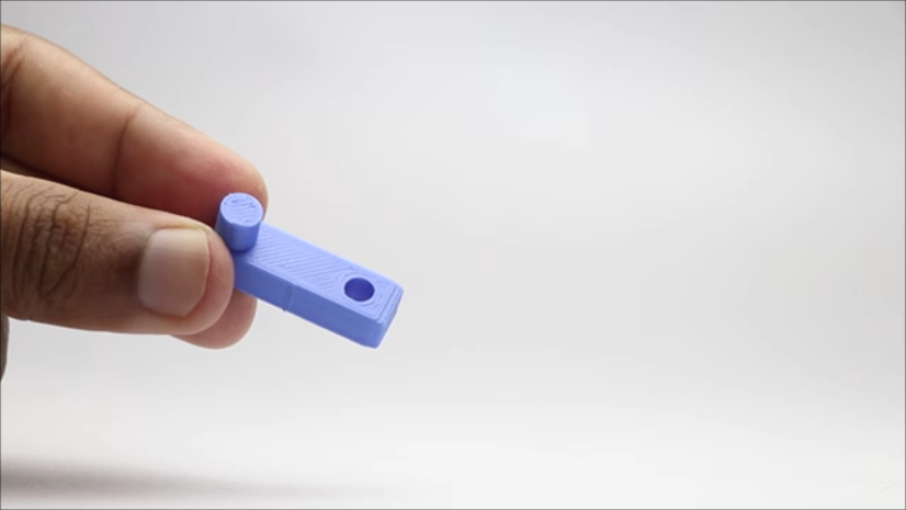
These are the materials that you will need to make this flashlight
Micro Servo(180 degree rotation)
Screw Driver to modify the servo
LED panel(5x5 smd i used)
Super Glue
Four Screws(can use from the micro servo)
3D Printer
Slicing Software
Tinkercad(if you want to edit my design)
PLA Filament
Soldering Lead
Soldering Iron
Jumper Cables(Optional)
Scenario where you can show off and put this flashlight to use!
note that these are affiliate links and upon qualifying sales i will get a small percent of sales at no extra cost to you
Designing the Flashlight
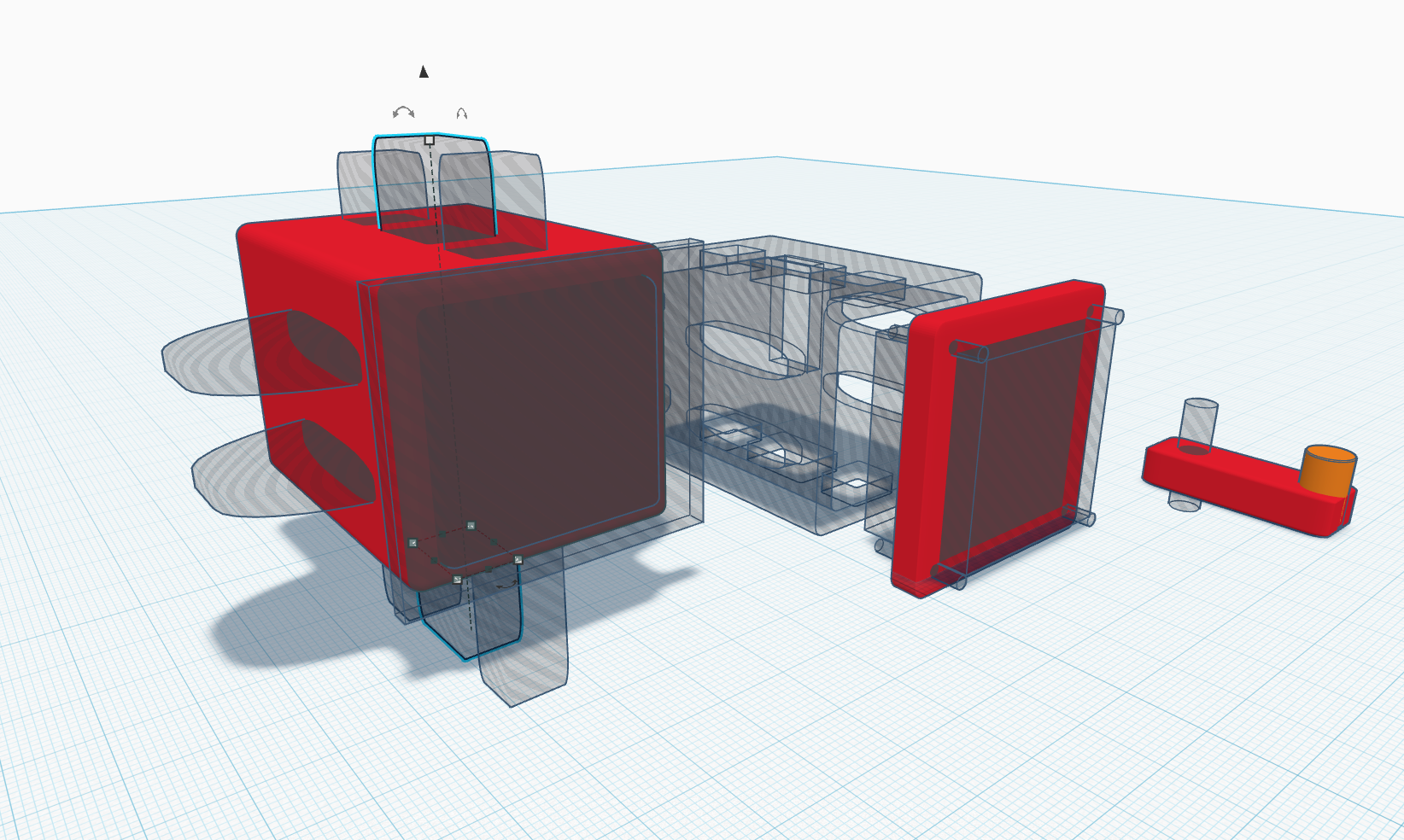
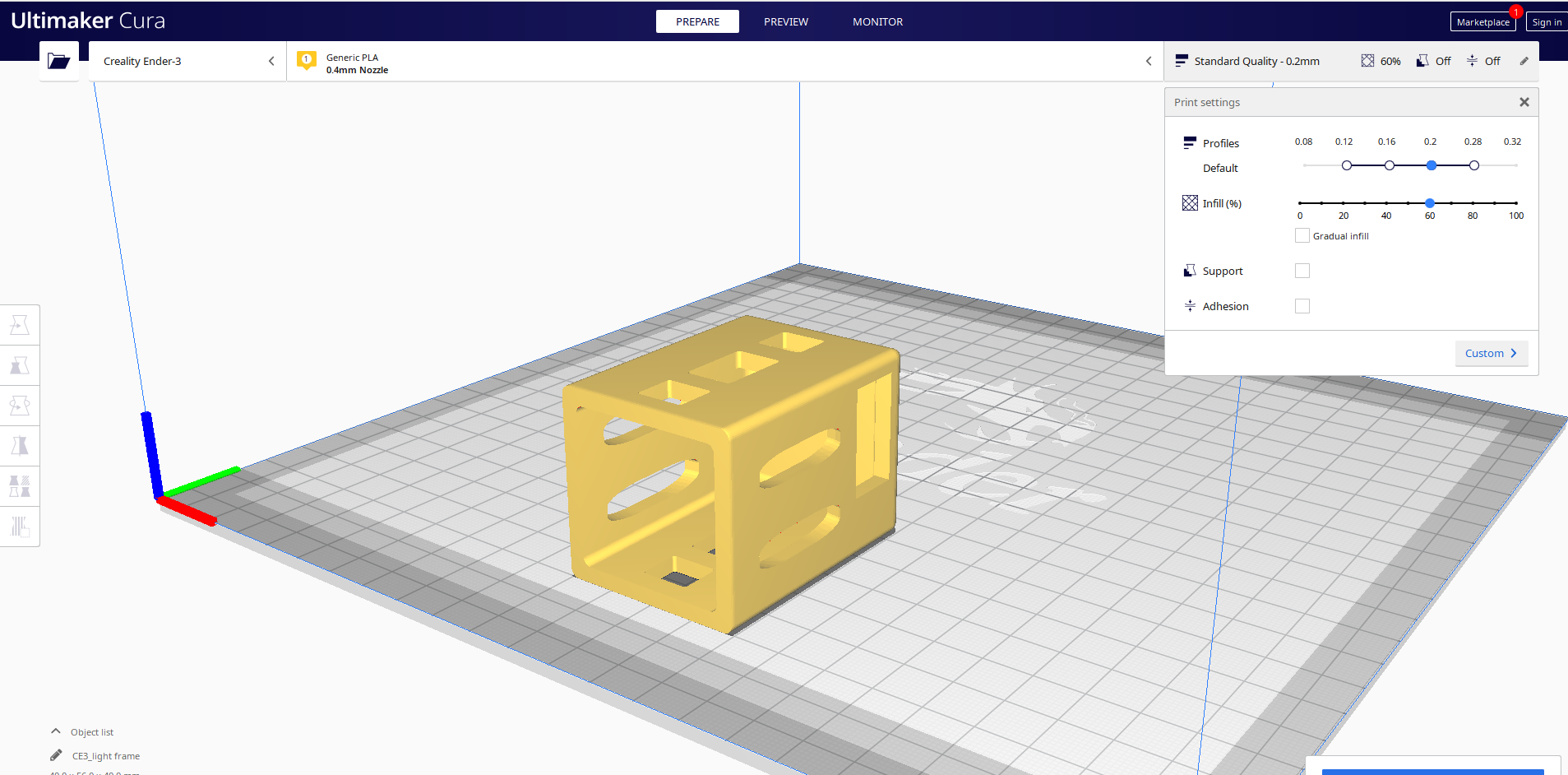
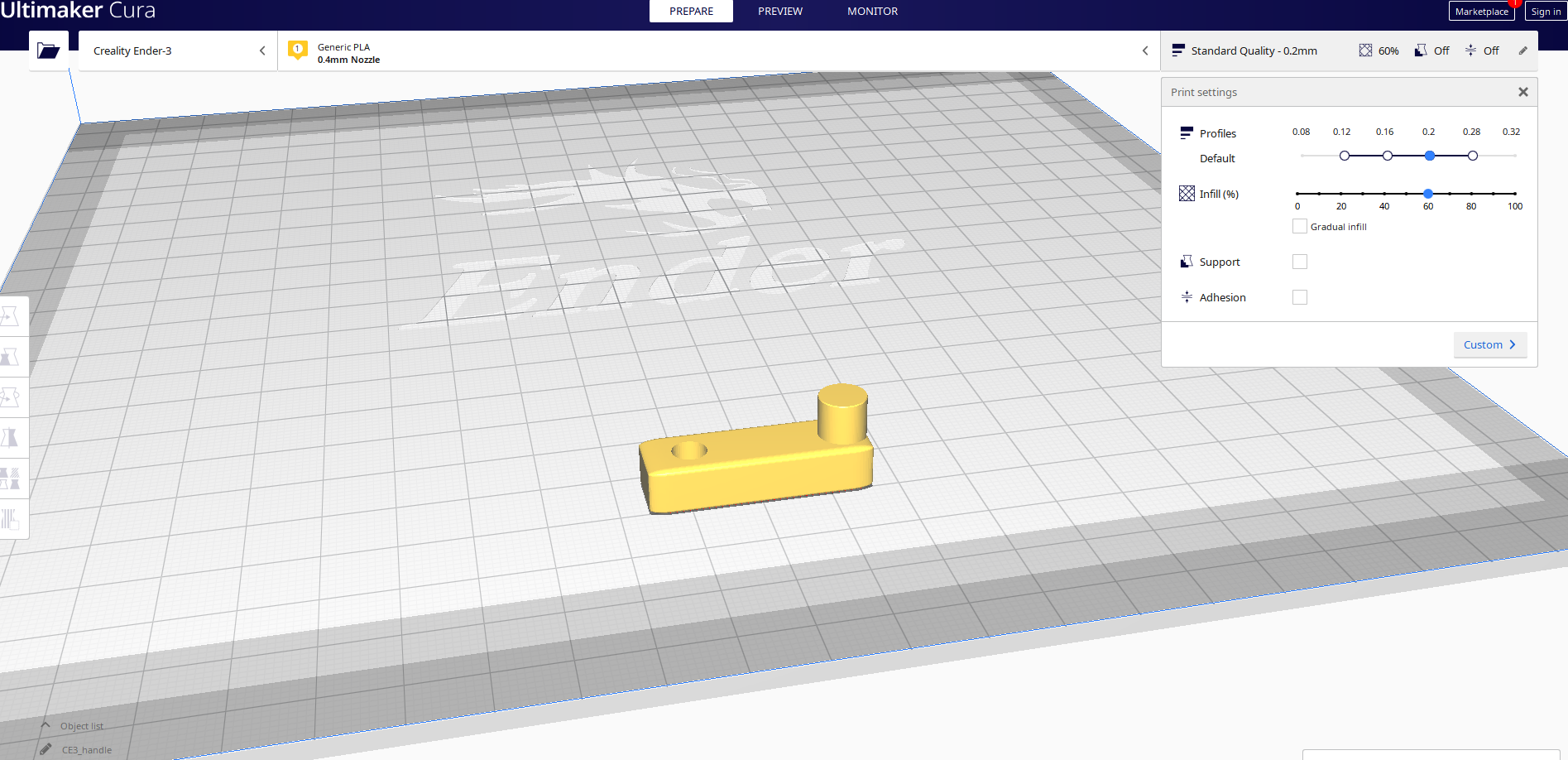
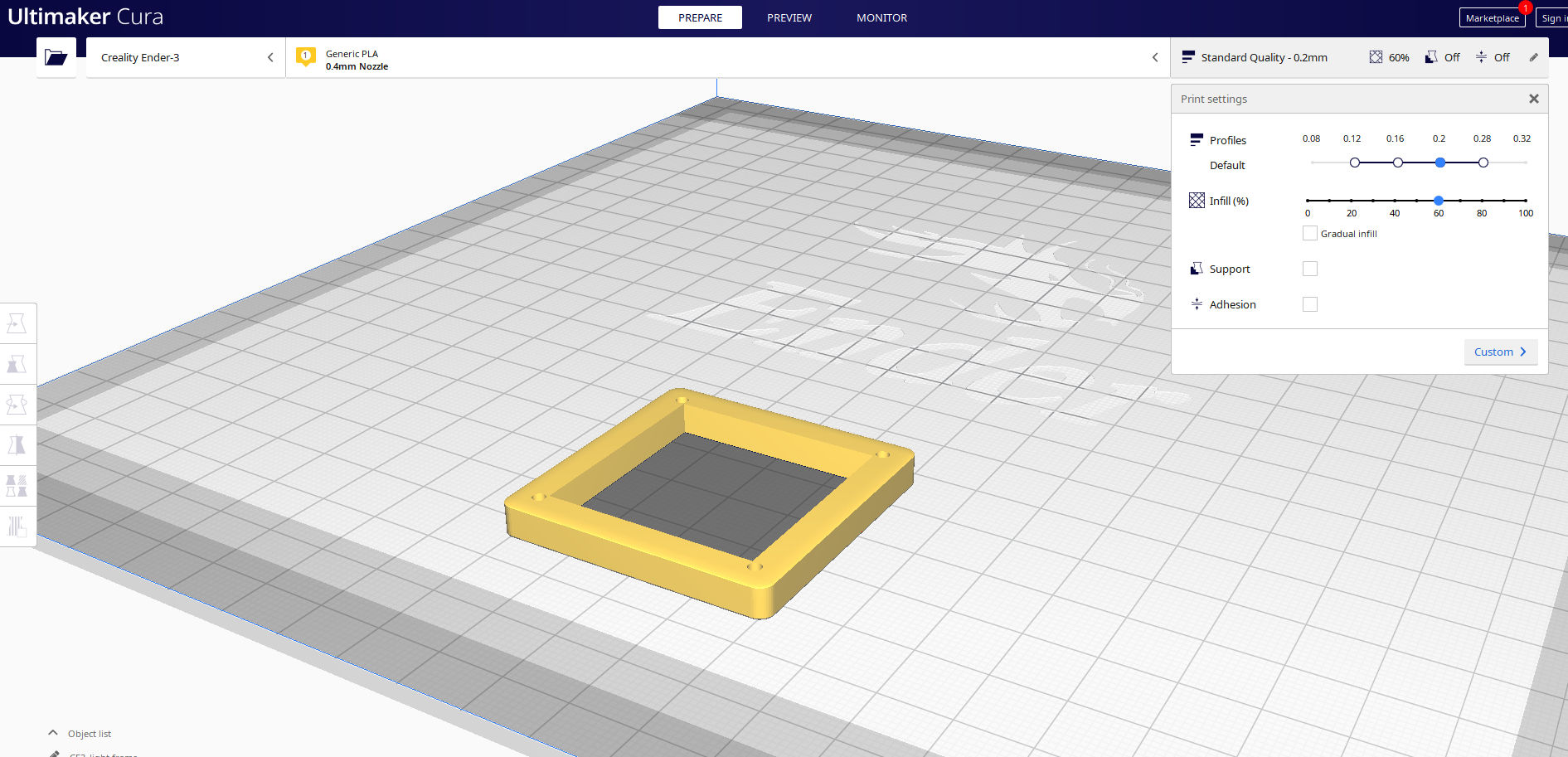
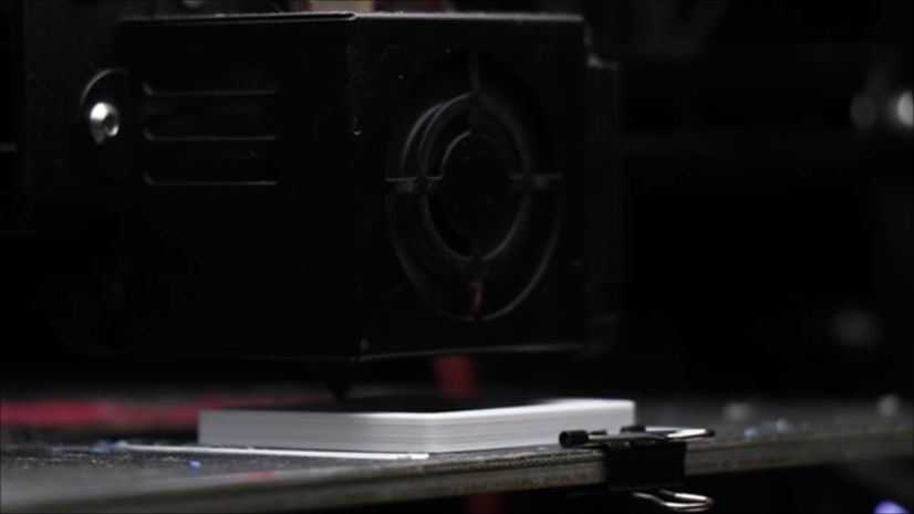
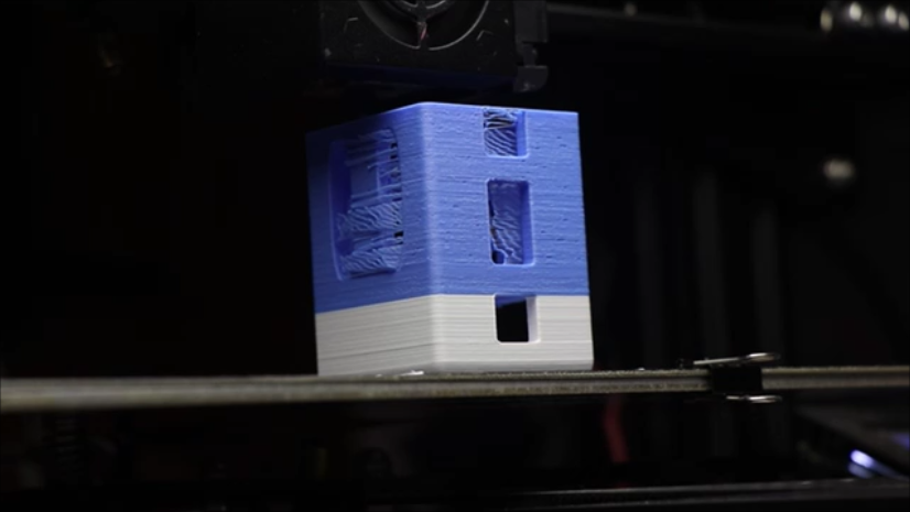
I will use Tinkercad to design the frame for this flashlight and if you wish to modify my existing design you can do it too.
There are total 3 parts in total and i have designed the main frame in such a way that natural circulation of air happens and the LED remains regulated with temperature if it glows for a longer time.
Main frame has many vents and you can see that from the design itself, you can print the parts all together or one by one.
I have used cura slicer to slide the model, you can simply download and use my STL files given below.
Follow the settings as i used and is shown on the settings on the cura slicer, there is no need of any rafts or supports at the time of printing.
The cranking handle and the LED case are the smaller parts and can be printed in under 30 minutes.
I will use PLA filament to print the parts and the choice of color is left to you.
I chose to print in white and blue color.
There is no need to do any post-processing after the model is printed as we are not using any overhangs or adhesion at the time of printing.
More infill rate gives more strength to the model and i recommend to use between 50 to 60% rate for the best print.
Tip: Keep the model for printing and in the meantime you can modify the servo for continuous rotation and thereby you can increase the overall build speed of this project.
Modifying the Servo Motor Gears
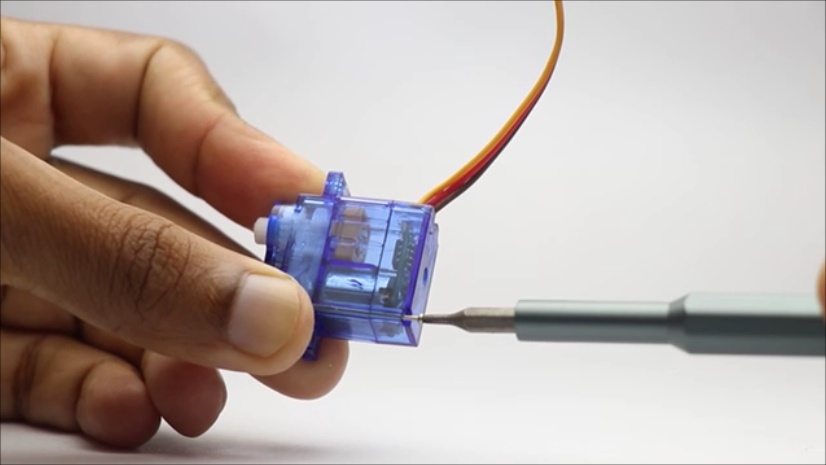
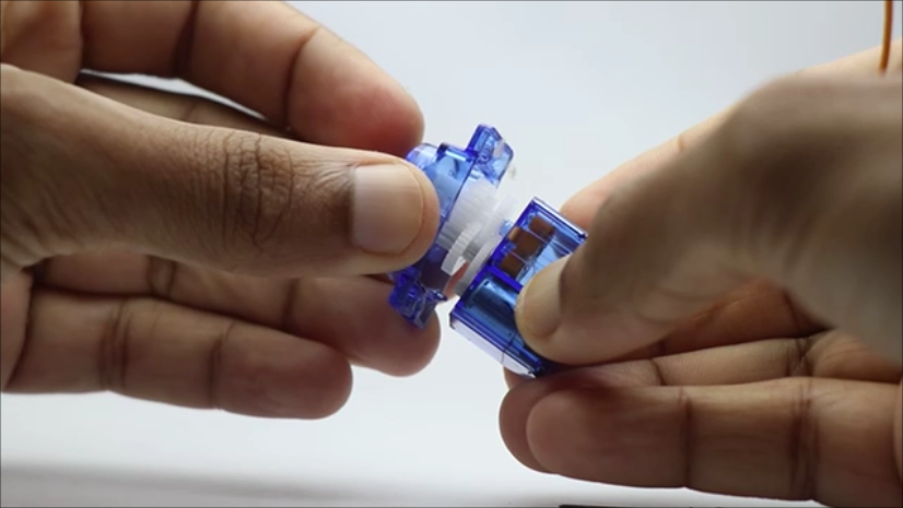
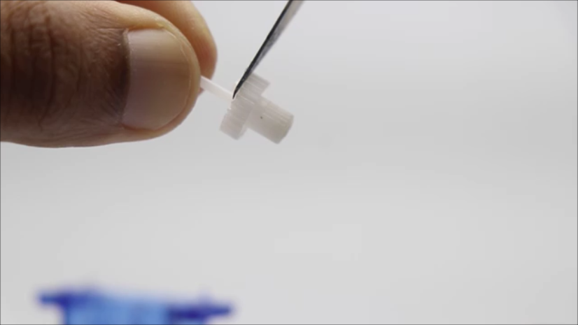
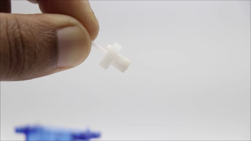
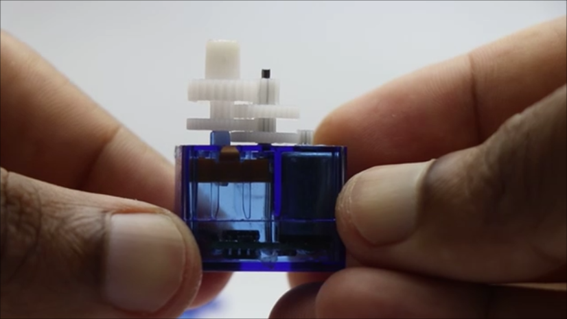
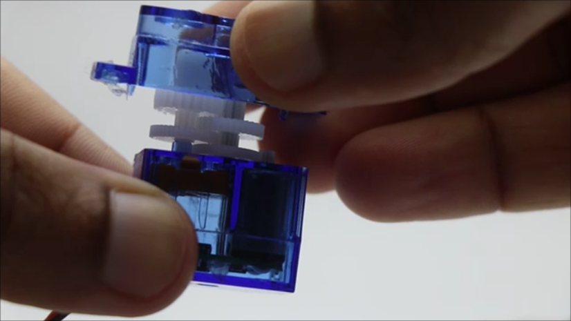
The micro servo also called as the 9g servo comes with a lock and it can only rotate only 180 degrees, There are 2 things here that needs to be considered for unlocking this lock and make it to rotate continously.
The gear has a tiny bumb that limits the rotation and also in the circuit level there is a potentiometer inside thar limts the rotation.
So to begin with i will remove the lock from the gear and to do this we need to work on the gear box.
Start by unscrewing the base screws using the star driver and you can access the gearbox after you remove the 2 long screws.
From the third image on this step you can see the gear that limits the rotation and this tiny bump needs to be removed, use a small cutter to remove this.
Put this gear back to the place where it was and now the gear modification is complete.
I will put the case back on and now remove the back plate(base) and work on the circuit level lock.
DC Motor Modification
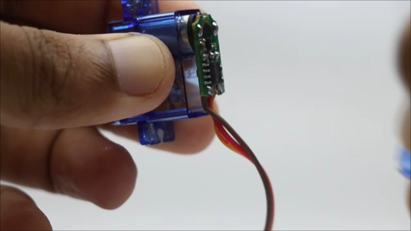
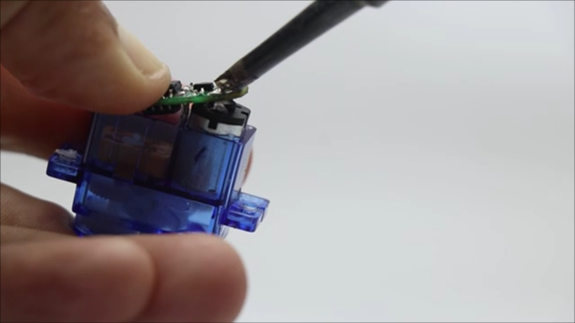
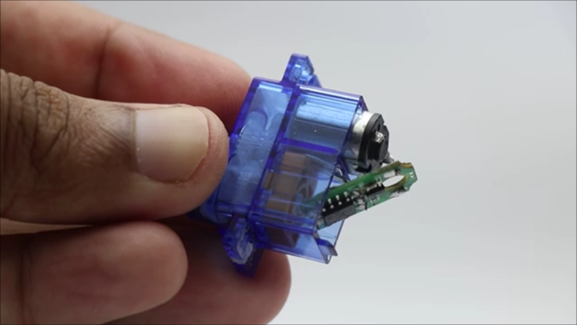
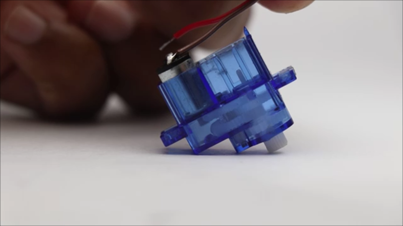
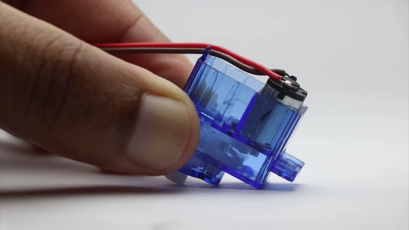
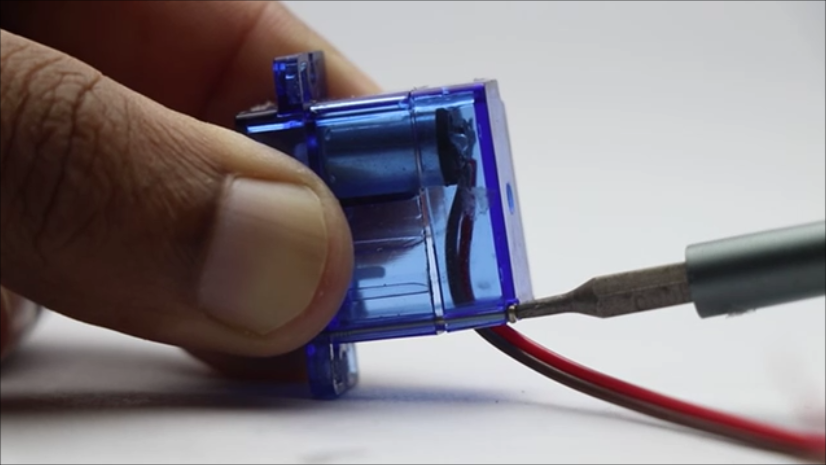
After the gears are modified we can head over to the base part of the servo or the wiring part.
There will be a small microcontroller that controls the motor speed and direction and we dont need this so unsoldered this circuit board and there will be 3 connections beneath this board.
The connections will control the onboard potentiometer and these needs to be disconnected and after doing this remove the circuit board.
Solder the wires directly to the motor and now from the 3 wires we will only have 2 wires and that will be for positive and negative power connection.
Since this is a dc motor interchanging the terminals will cause the dc motor to spin in the reverse direction.
After this is complete, Ensure the soldered joints are strong enough and close the back lid.
Insert the screws and tighten them with the help of screw driver.
Now the motor is ready, just connect the motor to any 3v dc supply and check for the working and if you followed everything properly it will work without any issue.
Circuit Installing
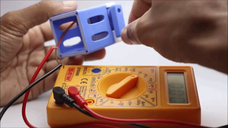
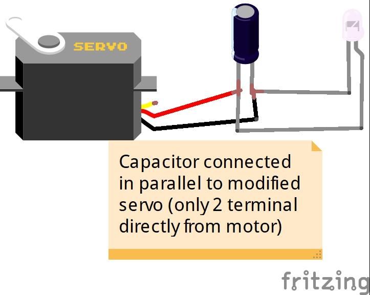
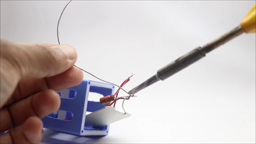
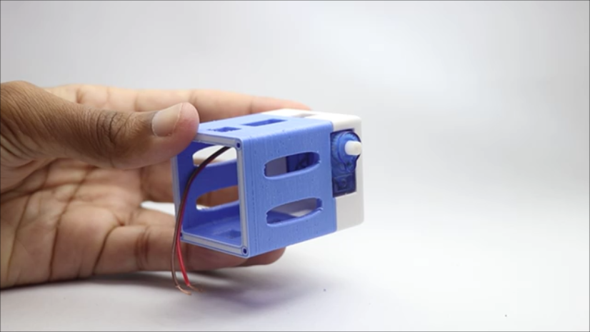
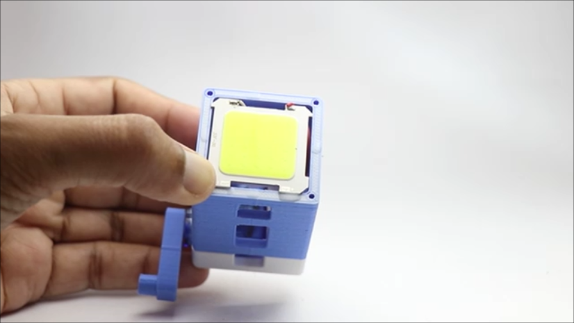
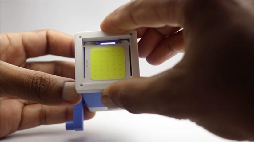
The circuit is really simple and if you are a begineer you get to learn a lot of things from this circuit!
Start by connecting the motor with LED panel and give the crank few turns and see if that direction of rotation is comfortable for you.
If yes, leave the connection to be same if you want the other direction then simply interchange the wires of motor with LED panel.
Now the capacitor is connected in parallel, meaning the direction of connection of motor and LED and alongside.
I later soldered these so that the connections wont break even after hard use and shakes.
Since the connections are complete now just go ahead and install these to the dedicated slots provided.
Anyways the servo will be placed in the slot given and the fit is soo perfect the superglue becomes optional here.
You can add but it is not necessary, Then add tiny drop of glue to the crank holder here make sure only small quantity is used because it may damage the servo shaft and gears.
Now insert all the wirings inside the 3d printed case, Place the LED panel on the 3d printed frame.
Don't use any hot glue or superglue here, we have a 3d printed frame that will help to hold this in place and also some extra spacings are given for proper light distribution.
Here using the white 3d printed case is a nice idea since it will illuminate the light to some extent when compared to other colors.
Finishing and Using
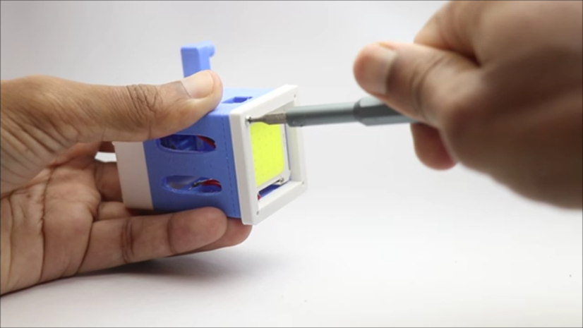
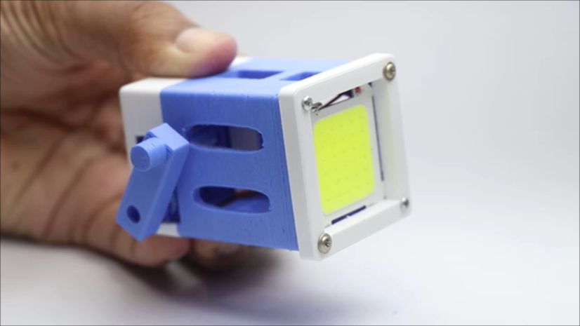
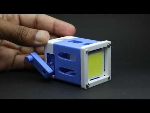
Finishing is nothing but tightening the screws on the LED holder case that goes directly connected to the frame, Here you can simply use the screws from the servo (given along with the extra horns).
I will use 4 screws and tighten them up using the star type screw driver, This is essential since if you are using superglue instead of screws if the led doesnt work its difficult to replace.
If you are using this removable type enclosure method replacing the components will be easy.
You may now ask does the LED heat? It does to a small extent and since the LED comes with a back heat sink plate connecting this directly to 3d printed frame does not cause any problem.
Now to use this all you have to do is turn the crank after 2 turns you will see the LED glowing.
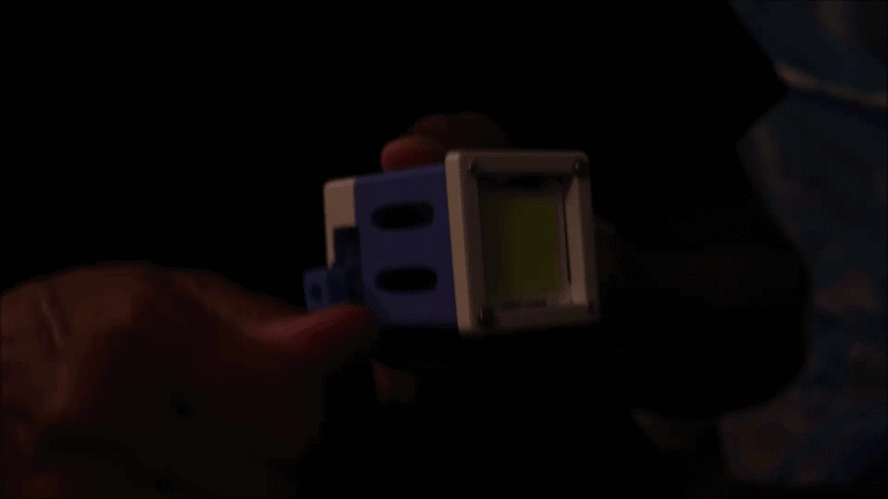
The LED glows very bright and i have tested this on a dark room and it is bright enough to illuminate the entire room.
Keep cranking and you will see the bright light and dont worry about the led burning because the LED is rated to 12v whereas the servo can generate max 8v at peak speeds!
This was all about this project, If you have any questions ask me and i will be happy to answer them.
Consider watching the build tutorial video with the testing of brightness from this flashlight and suggest me if any changes coule be made to further improvise.
Also im expecting many makes of this project on this instructables i made it section! Thank you for showing interest and have a great build.