RE:VOLT — a Hand-Crank Emergency Power Bank & Smart Lamp
by ayushmaan45 in Circuits > Gadgets
145 Views, 3 Favorites, 0 Comments
RE:VOLT — a Hand-Crank Emergency Power Bank & Smart Lamp
Hey everyone!
I’m Ayushmaan, a B.Tech E.E.E. student, and I’ve always liked building projects that feel more like actual products than random electronics experiments.
This project started with a pretty simple idea:
“What if a power bank could generate its own power when there was no electricity available?”
Obviously, hand cranking isn't going to replace a wall charger. But the idea of generating electricity when no other power source was available sounded interesting enough to explore.
That’s how RE:VOLT — A Hand-Crank Emergency Power Bank & Smart Lamp started.
A geared DC motor acts as a generator when the hand crank is rotated, and the generated power is regulated and stored in rechargeable 18650 batteries. Since the project already had a battery pack, I also added a built-in lamp with separate White and Warm White LED channels, controlled using a Seeed Studio XIAO ESP32-C3 and physical buttons.
For the LED control system, I reutilised a custom PCB originally designed by Arnov Sharma for his Web-Controlled Desk Lamp With XIAO ESP32-C3 project and adapted it for this build.
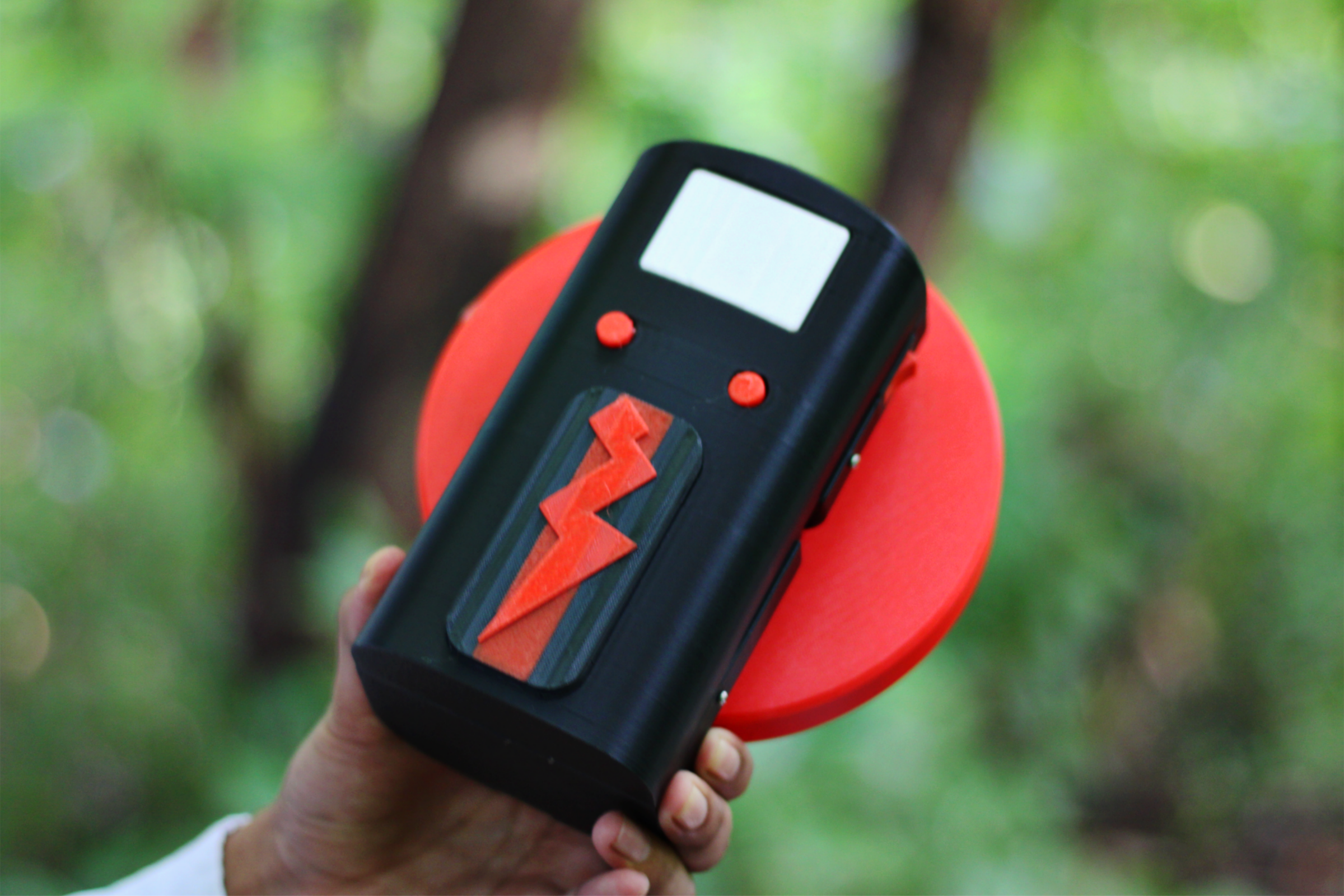
I then designed and 3D printed an enclosure around the electronics, batteries, motor, and gear-driven hand crank. I wanted the final project to feel like an actual device rather than just a collection of modules connected together.
The goal was never to build the most practical hand-powered generator. I just wanted to combine power generation, battery charging, embedded electronics, and mechanical design into something fun and technically interesting.
So, let's get started!
Supplies
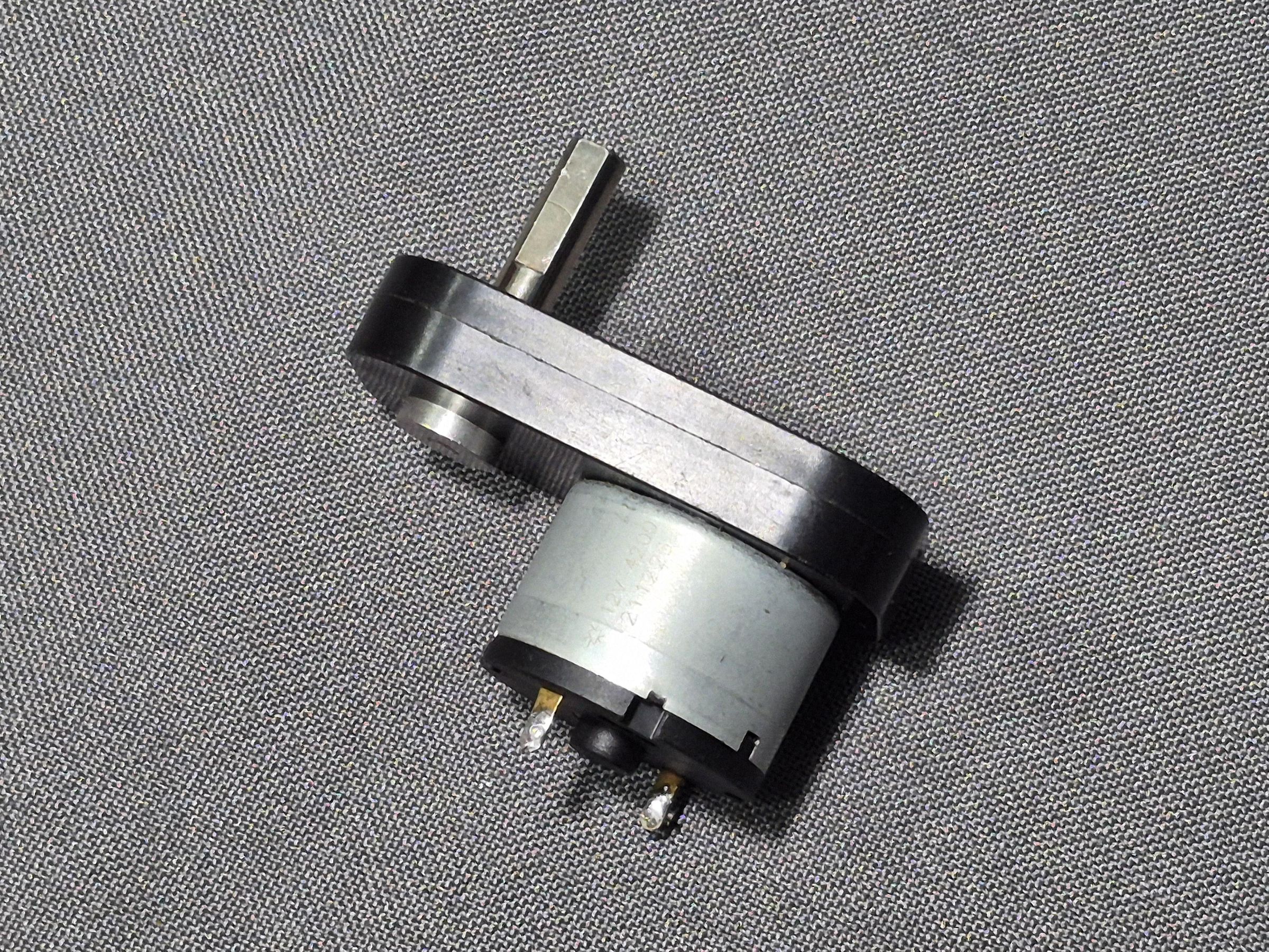
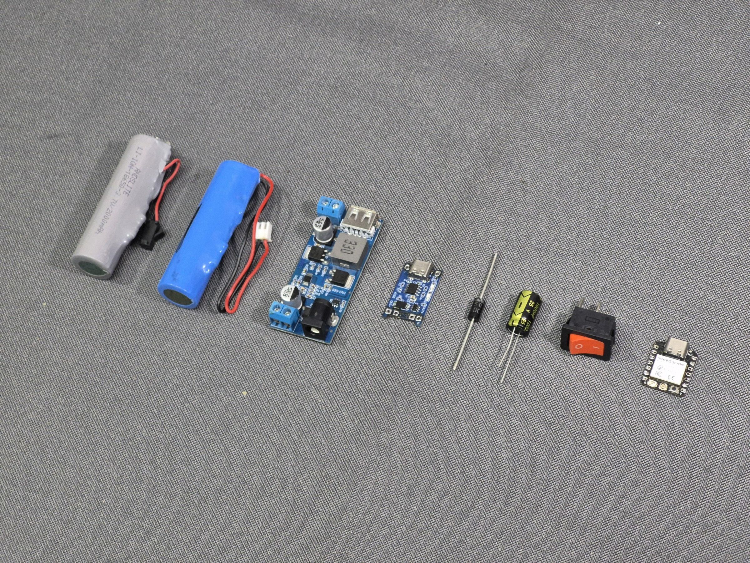
Here’s everything I used to build RE:VOLT. The project uses a mix of separate modules and a custom LED control PCB that I reused from another project.
Power Generation and Charging
- DC Geared Motor
- 1N5408 Rectifier Diode
- 1000µF, 36V Electrolytic Capacitor
- LM2596 Buck Converter Module
- TP4056 USB-C Lithium Battery Charging Module
- 2 × 18650 Li-ion Batteries
- Rocker Switch
LED Control PCB
- Seeed Studio XIAO ESP32-C3
- White LED array
- Warm White LED array
- 2 × N-channel MOSFETs
- MOSFET gate resistors
- MOSFET gate pulldown resistors
- 2 × Tactile Push Buttons
- XIAO Header Pins
Building the Power Generation System
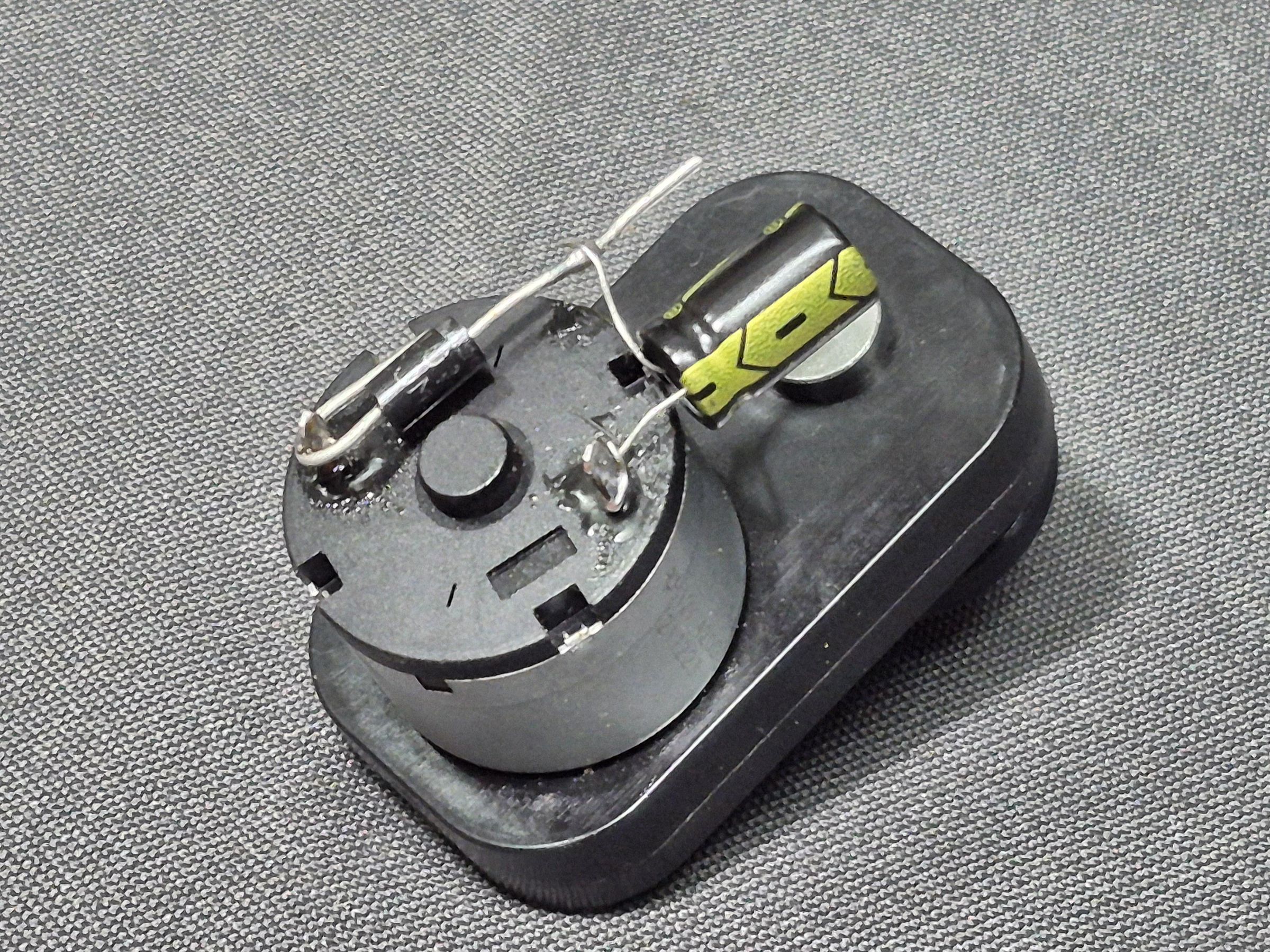
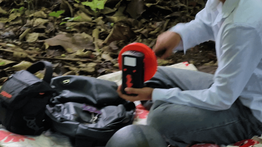
For generating power, I used a small DC geared motor. When rotated using the hand crank, the motor acts as a generator and produces a voltage across its terminals.
Since hand cranking produces a fairly inconsistent output, I added a simple diode-capacitor protection and filtering circuit. The 1N5408 diode prevents reverse current from flowing back into the motor, while the 1000µF, 36V capacitor acts as a small energy buffer and helps smooth out sudden voltage fluctuations.
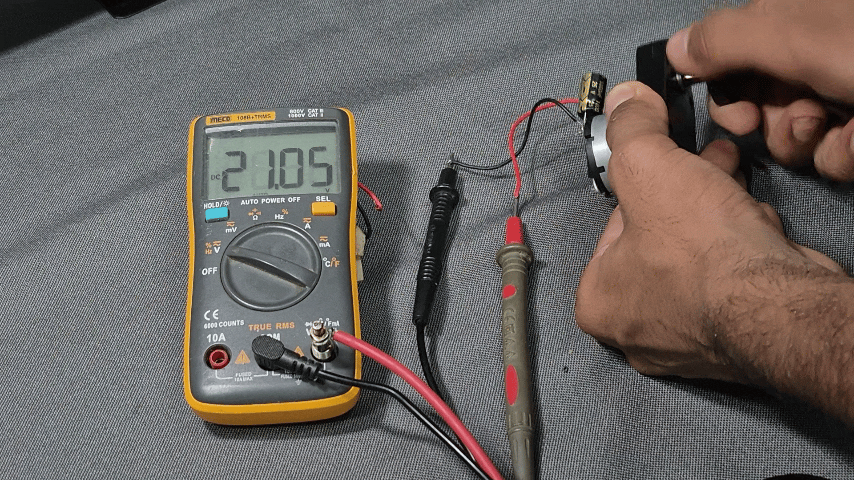
I also tested the generator output using a multimeter. As expected, the voltage changed significantly depending on how fast the crank was rotated. During faster rotation, the output reached around 20V, while slower rotation produced a much lower voltage.
This is also why the generator cannot be connected directly to the battery charging circuit. The output needs to be regulated first before it can be used for charging the batteries.
Regulating the Generator Output
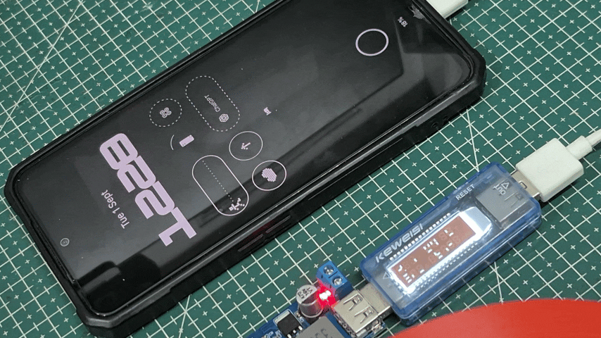
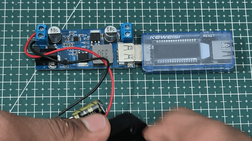
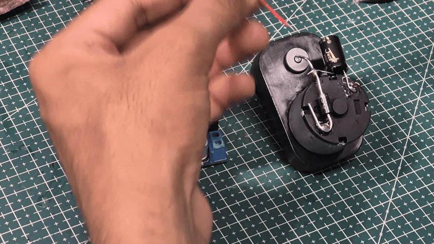
The voltage coming directly from the generator isn't stable enough to use for charging the batteries. It changes significantly depending on how fast the hand crank is rotated.
To regulate this, I used an HW-688 DC-DC buck converter module, which provides a fixed 5V output.
During testing, I found that the generator needed to produce around 9V or more for the module to reliably provide a 5V output. Since the generator voltage depends entirely on the cranking speed, the handle needs to be rotated fast enough to maintain this input voltage.
Once the input reaches a sufficient level, the module converts the generator output into a usable 5V supply for the battery charging circuit.
Charging the Batteries
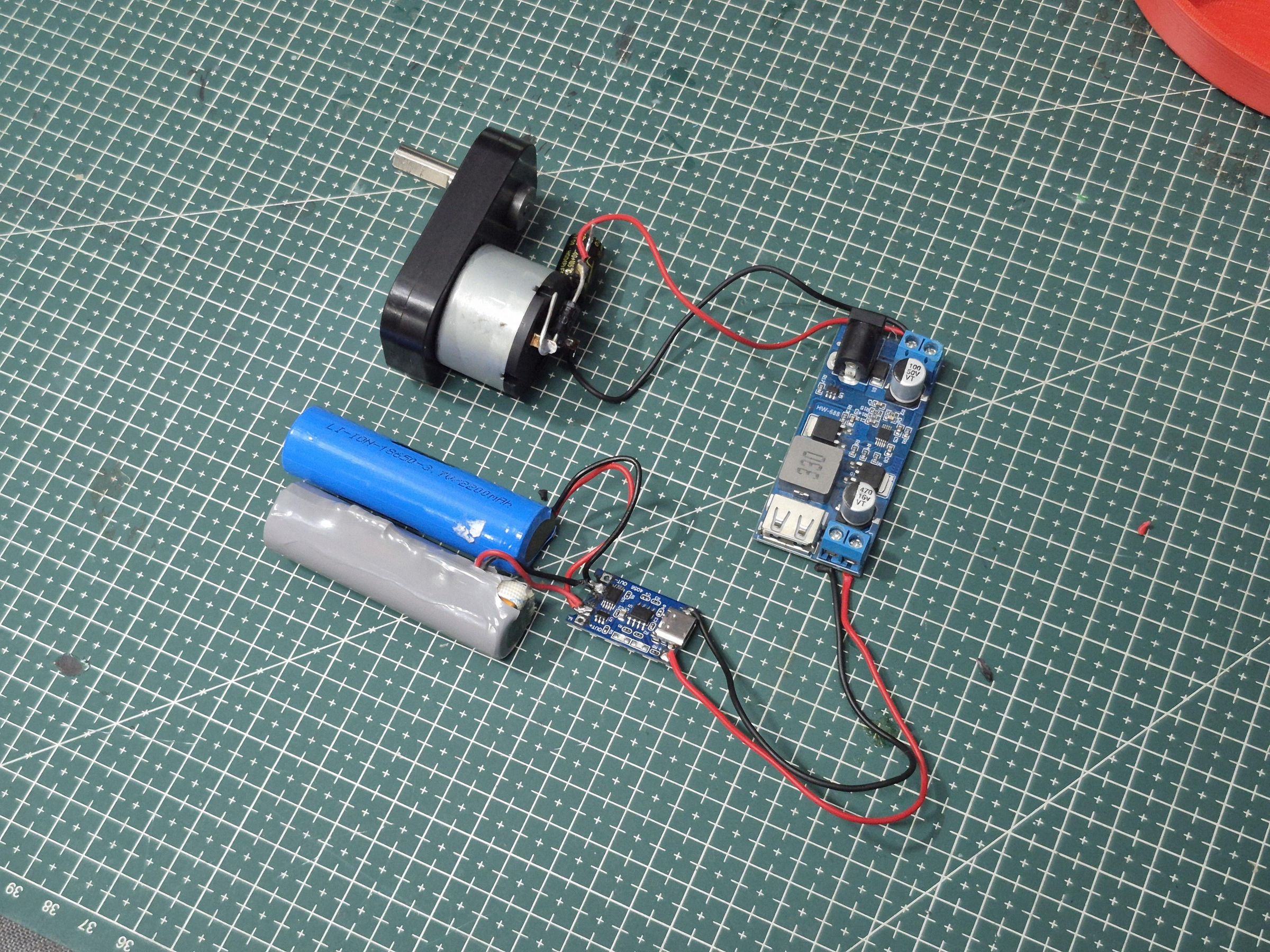
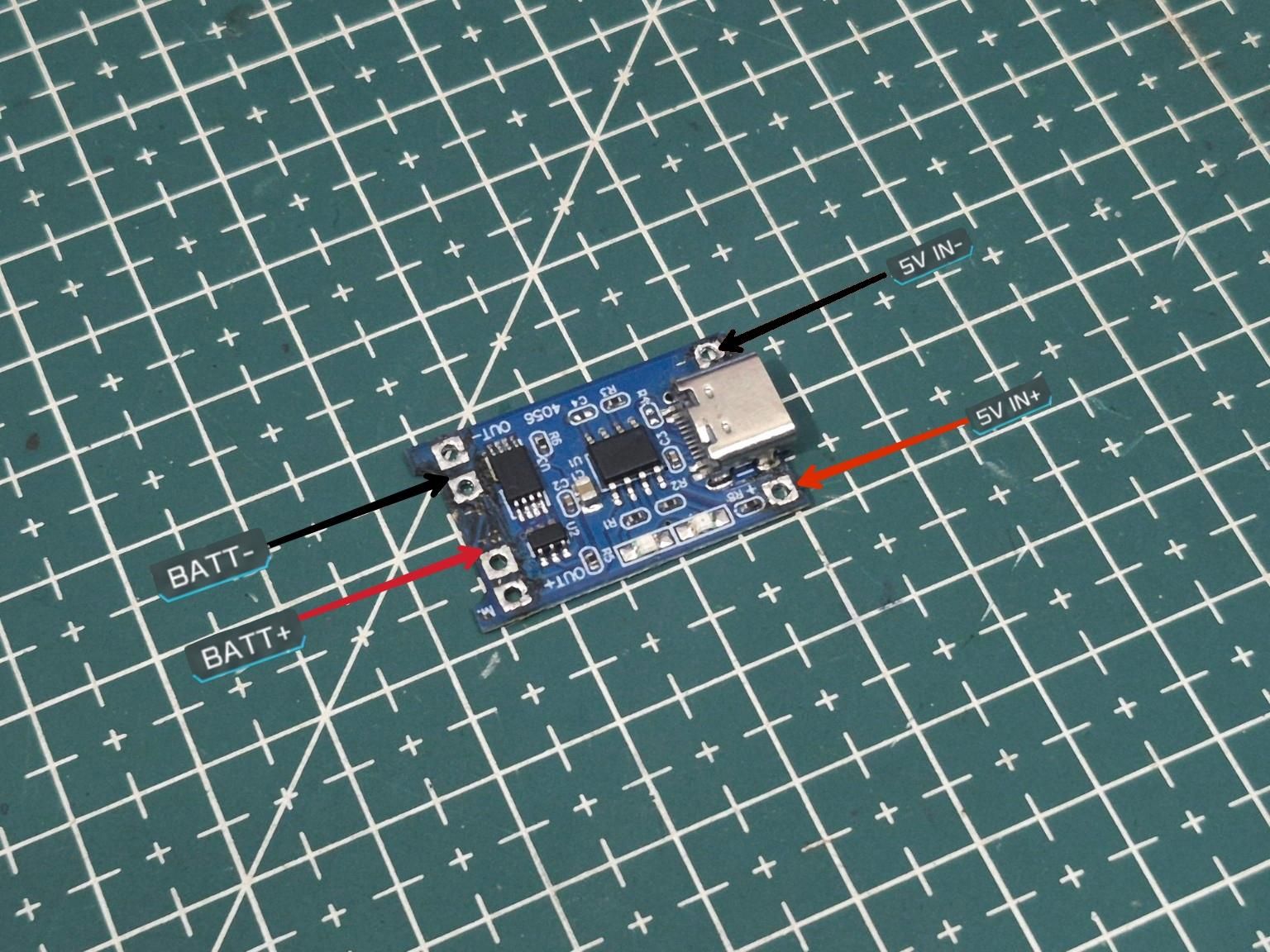
For storing the generated power, I used two 18650 Li-ion batteries connected in parallel. Connecting the cells in parallel keeps the voltage the same while increasing the overall battery capacity.
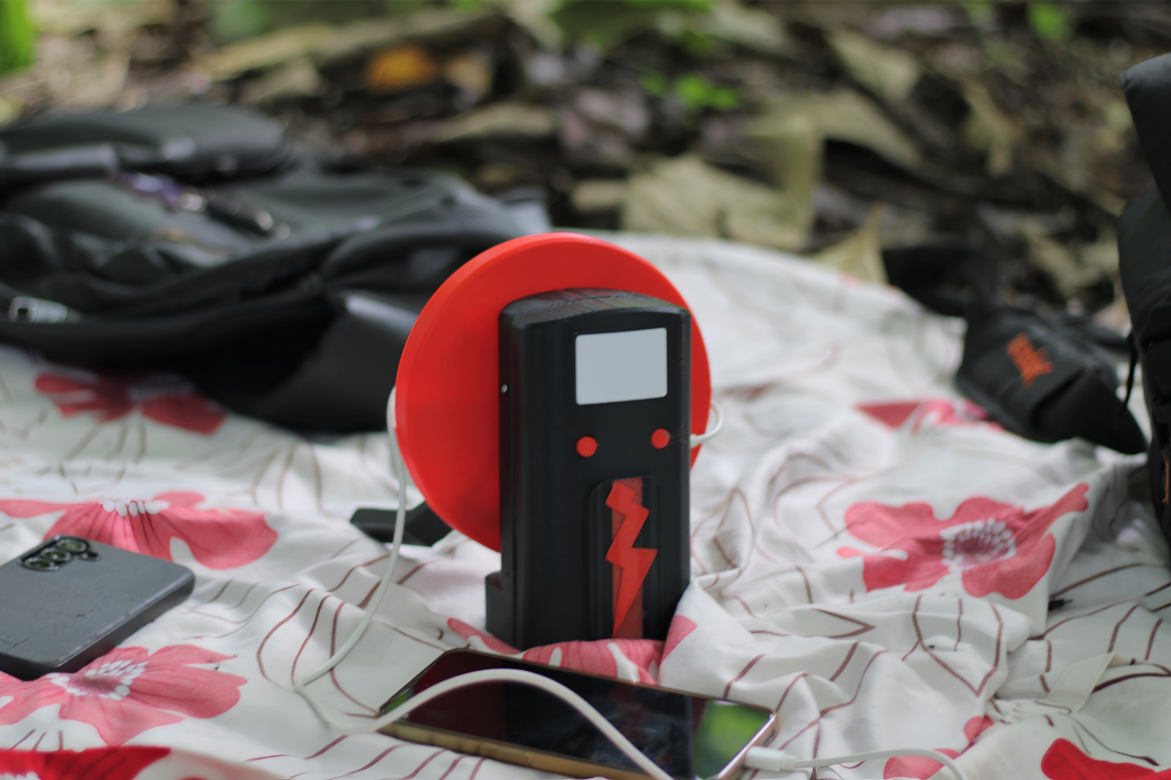
To charge them, I used a TP4056 USB-C lithium battery charging module. The regulated 5V output from the HW-688 is connected to the input of the TP4056, which handles the charging process for the battery pack.
The TP4056 is designed specifically for charging single-cell lithium-ion batteries, so using the two 18650 cells in parallel allows them to behave as a single 1S battery pack.
This way, the power generated by the hand crank is first converted to 5V and then safely used to charge the batteries.
The LED Control PCB
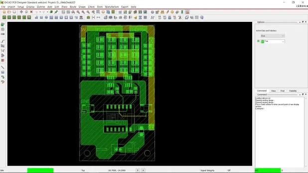
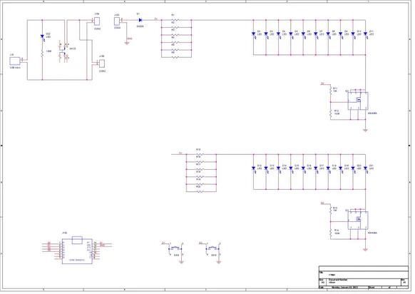
For the lighting section, I decided to reutilise a custom PCB originally designed by Arnov Sharma for his project, Web-Controlled Desk Lamp With XIAO ESP32-C3.
The original PCB was designed around a Seeed Studio XIAO ESP32-C3 and included separate sections for controlling two LED channels. Since the design already had most of what I needed for this project, I decided to reuse it instead of designing another PCB from scratch.
For RE, I used one channel for the White LEDs and the other for the Warm White LEDs. The PCB also includes separate MOSFET driver circuits and two physical buttons, allowing both channels to be controlled independently.
The design fit the project surprisingly well, so I only had to adapt the existing PCB for my requirements.
Assembling the LED Control PCB
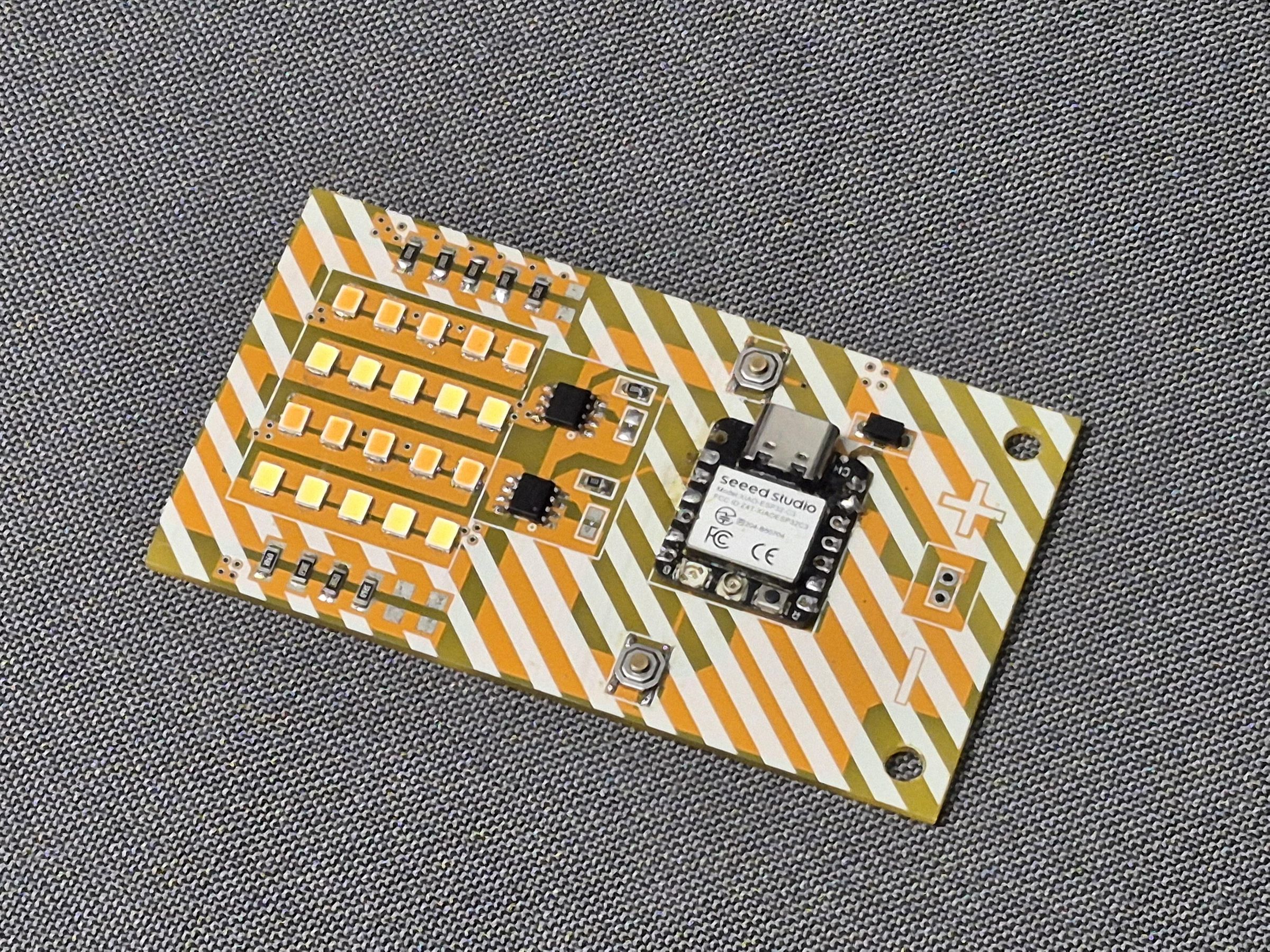
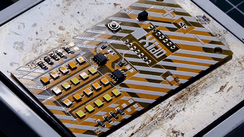
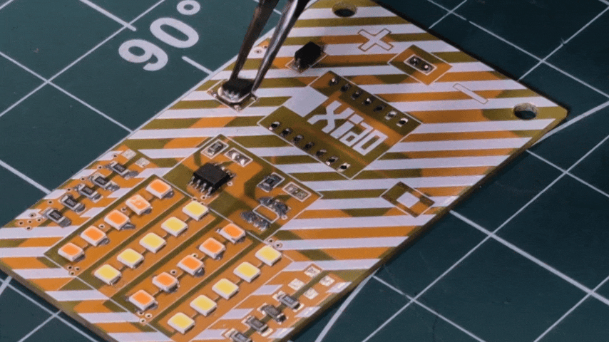
With the PCB design ready, it was time to assemble it.
I started by soldering the smaller SMD components, including the resistors and the AO3400A MOSFETs. The PCB uses two separate MOSFET circuits, one for each LED channel.
After that, I soldered the LEDs, tactile push buttons, and the required headers for the Seeed Studio XIAO ESP32-C3.
The two LED channels were populated separately, with one set using White LEDs and the other using Warm White LEDs.
Once everything was soldered, the PCB was ready to be tested and integrated.
Final Connections
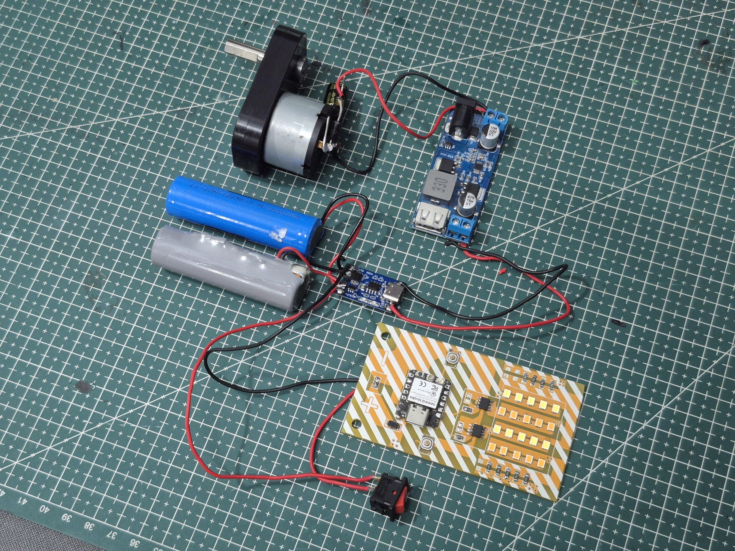
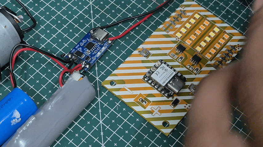
With all the individual sections ready, it was time to connect everything together. The power generation circuit was connected to the charging and battery system, while the regulated supply was routed to the LED control PCB.
The battery pack powers the main system, and the reused XIAO ESP32-C3 LED PCB controls the White and Warm White LED channels through its two MOSFET circuits.
At this point, all the separate parts finally came together: the hand-crank generator, power circuit, battery pack, and smart lamp PCB
Programming the LED Control System
With the PCB assembled, it was time to program the Seeed Studio XIAO ESP32-C3.
The code controls the White and Yellow LED channels independently using the two MOSFETs on the PCB. The lamp can be controlled using the physical buttons or through a simple Wi-Fi web interface.
Pin Configuration
The pin configuration follows the original PCB design.
This gives us the following connections:
- D0 / GPIO2: White LED MOSFET
- D1 / GPIO3: White LED Button
- D2 / GPIO4: Yellow LED MOSFET
- D3 / GPIO5: Yellow LED Button
PWM and Brightness Control
Both LED channels use PWM for brightness control. I used five predefined brightness levels:
So, every button press cycles through:
OFF → 25% → 50% → 75% → 100% → OFF
PWM is attached to both LED control pins using:
The brightness is then controlled by changing the PWM duty cycle.
Physical Button Control
The two buttons use the ESP32's internal pull-up resistors.
Each button controls its respective LED channel. Every press increases the brightness level, and after reaching 100%, the next press turns the LEDs OFF.
The same logic is used for the Yellow LED channel.
Wi-Fi and Web Control
The XIAO ESP32-C3 also connects to a Wi-Fi network.
After connecting, the ESP32 starts a web server and prints its IP address to the Serial Monitor.
Opening the IP address in a browser provides access to the lamp's web interface.
The interface allows both LED channels to be controlled independently. It can increase the brightness of each channel, turn individual LEDs OFF, or control both channels together.
For example, this checks for a request to increase the White LED brightness:
The Yellow LED channel works in the same way:
Main Loop
The main loop continuously checks both the physical buttons and incoming web requests.
This means the lamp can be controlled either using the physical buttons or through the Wi-Fi web interface.
Designing the Enclosure
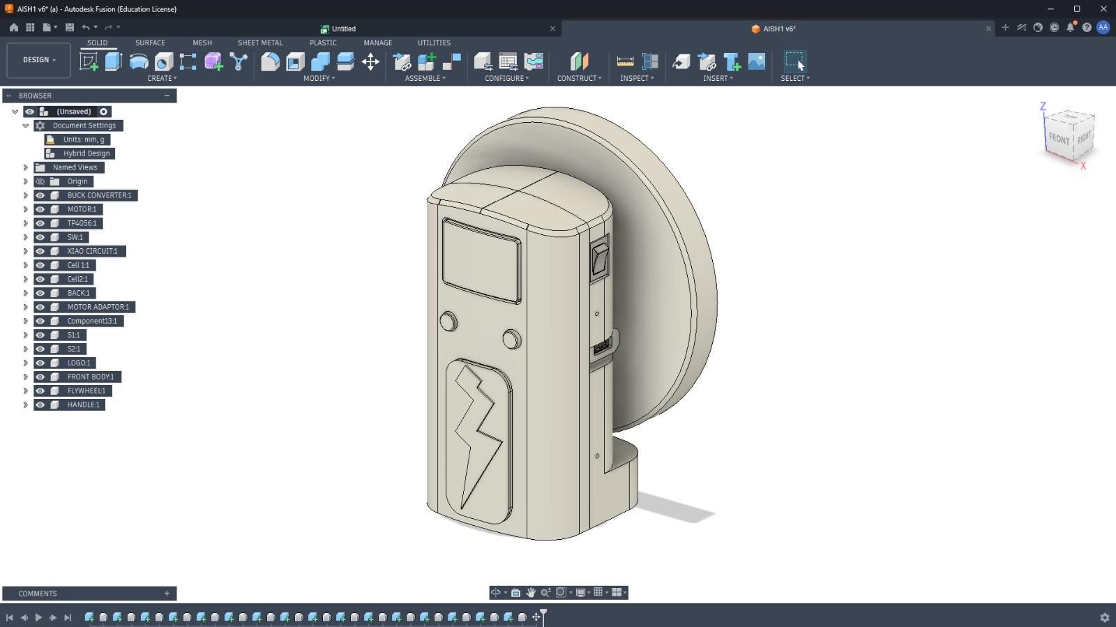
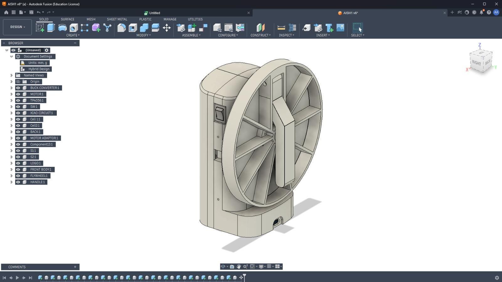
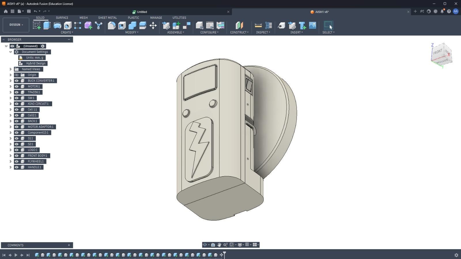
With the electronics ready, I designed the enclosure in Fusion 360. The idea was to fit the motor, batteries, PCBs, and hand-crank mechanism into a single enclosure.
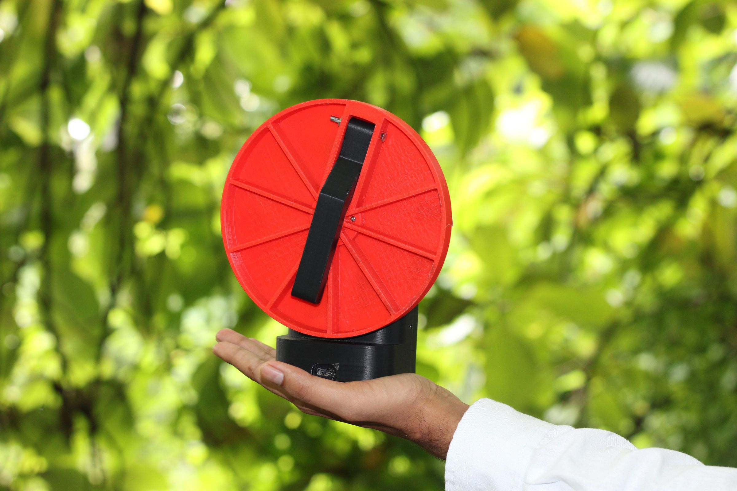
I designed dedicated spaces for the components and integrated the gear-driven hand crank directly into the enclosure. The crank handle can also fold when not in use.
The project isn't particularly compact, mainly because fitting the motor, gear mechanism, batteries, and electronics inside required quite a bit of space. Still, I wanted the final design to look more like a commercial product than a collection of electronics placed inside a box.
After a few adjustments to make sure everything fit properly.
3D Printing the Parts
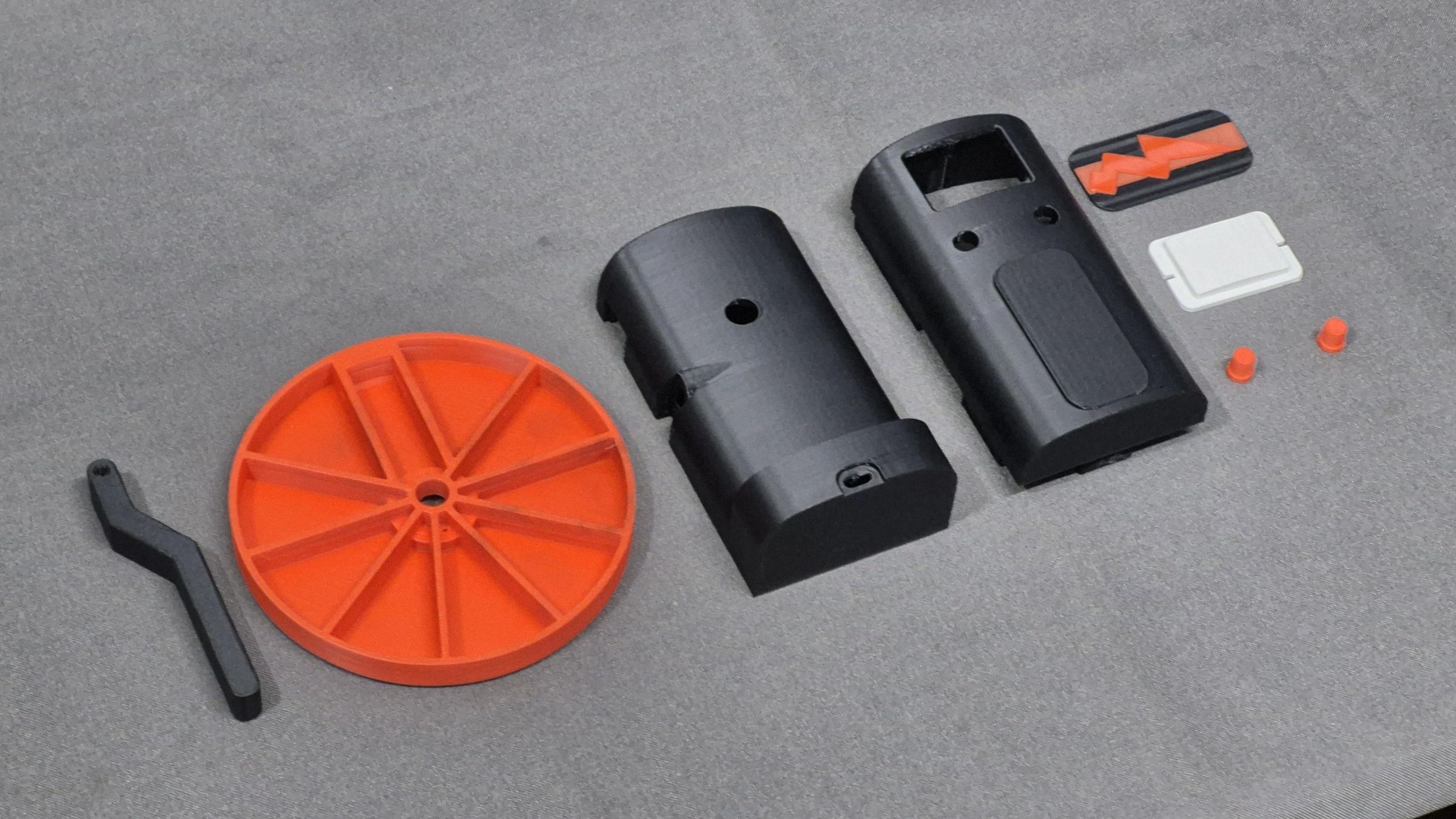
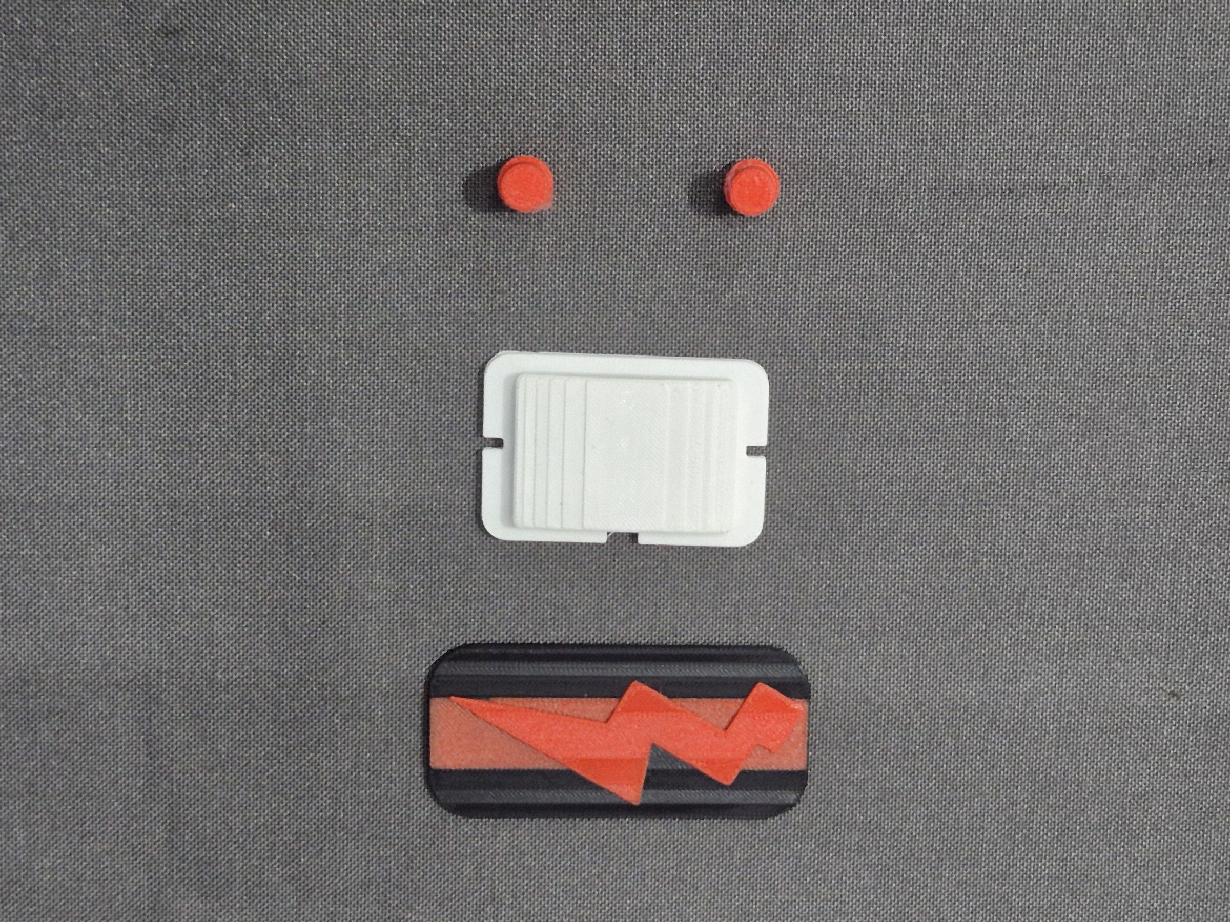
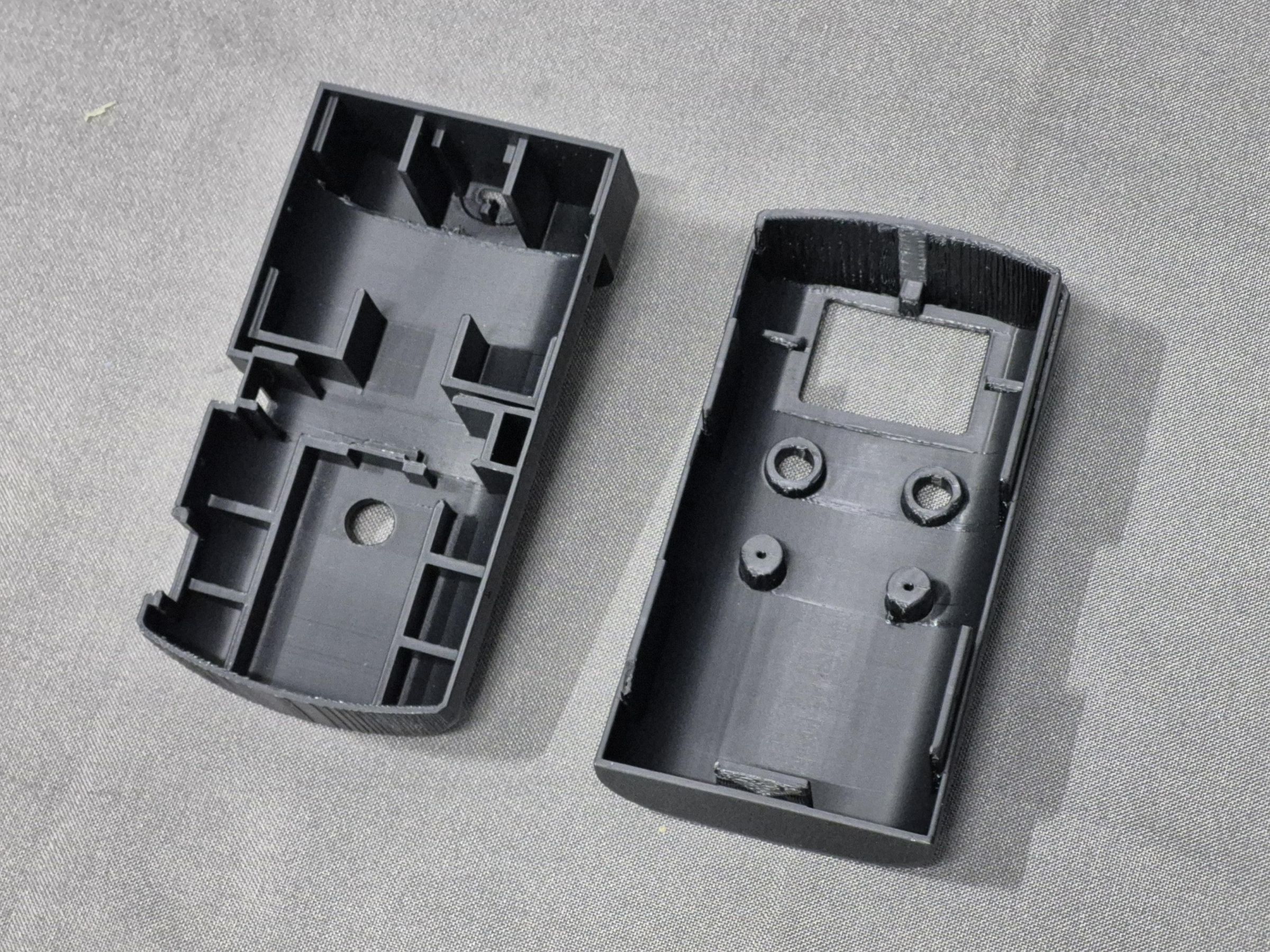
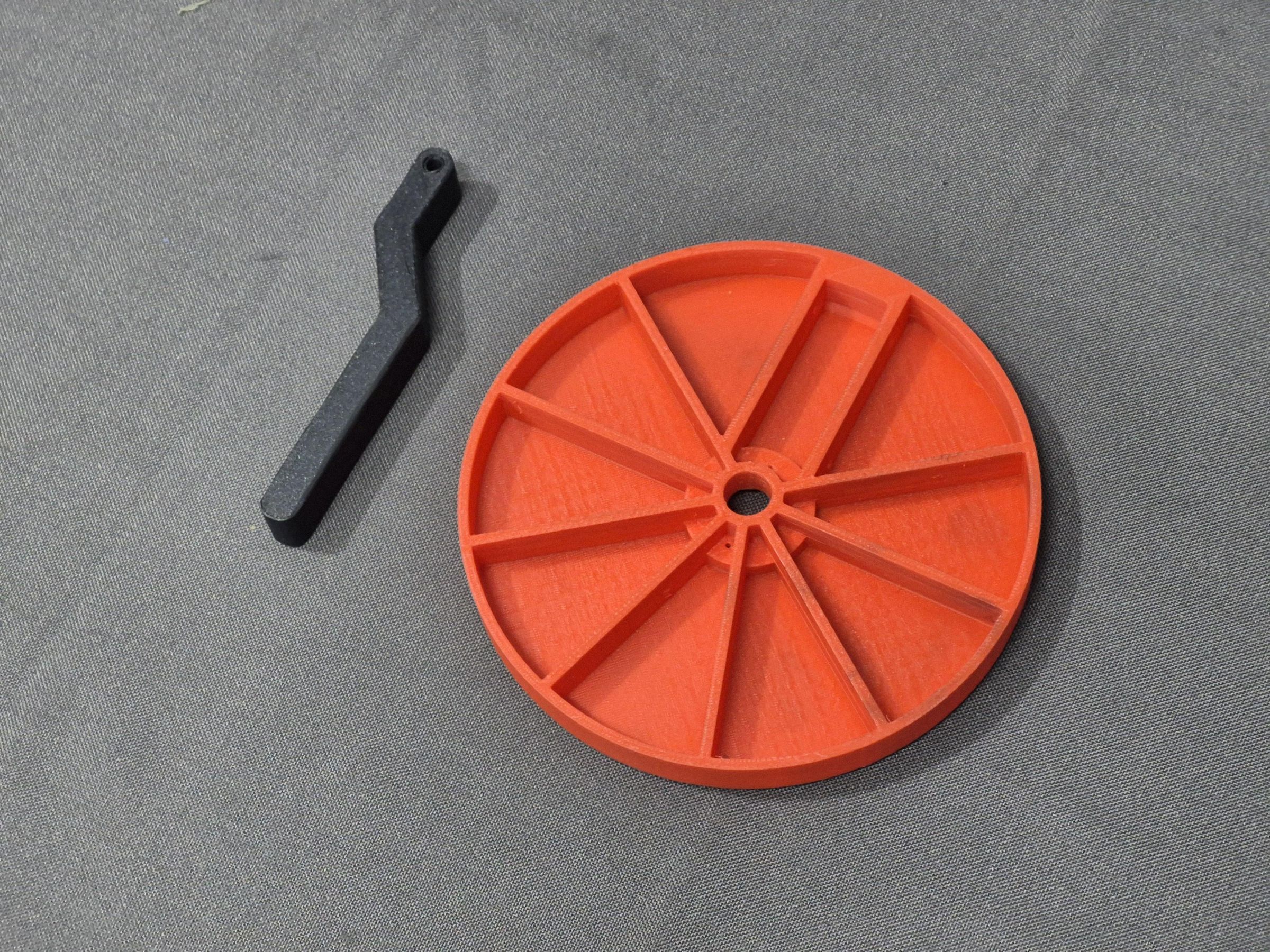
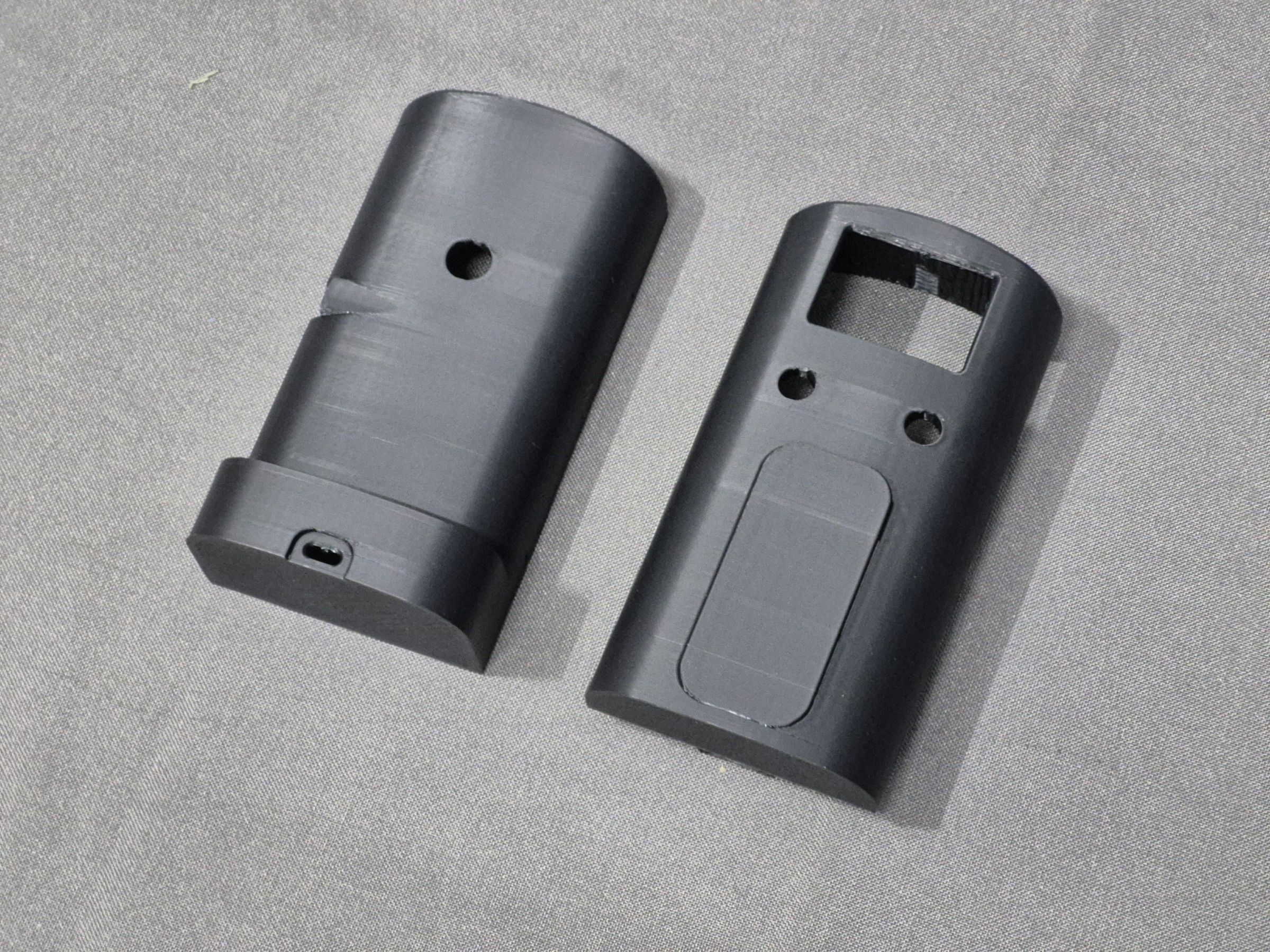
Once the design was ready, I exported all the parts from Fusion 360 and prepared them for 3D printing.
The enclosure was printed using PLA, with the main body printed in black and a few parts printed in red to match the overall design.
I originally wanted to print the LED diffuser using clear PLA, but I didn't have any available at the time. So, I ended up printing it using white PLA instead. It still works as a diffuser, although the final look is obviously a little different from what I originally had in mind.
After printing, I cleaned up the parts and checked the fit before moving on to the final assembly.
With all the printed parts ready, it was finally time to put everything together.
Final Assembly
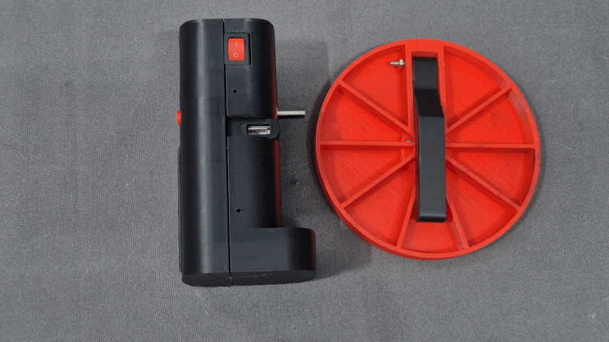
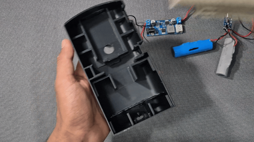
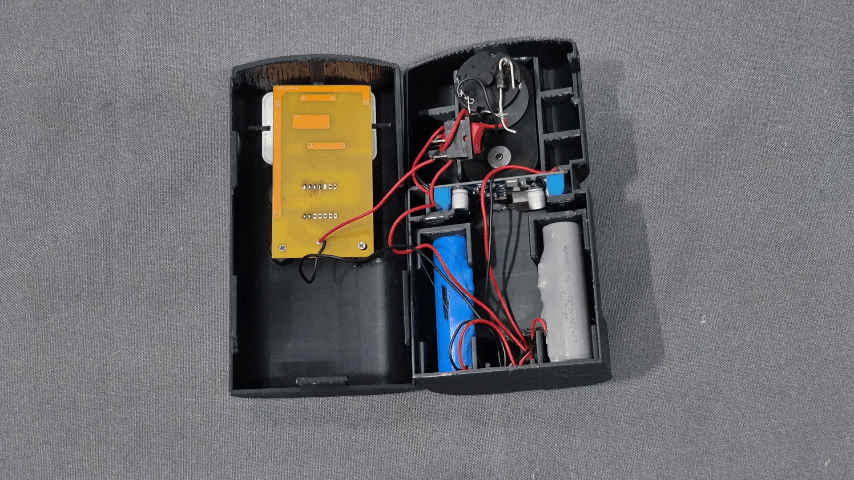
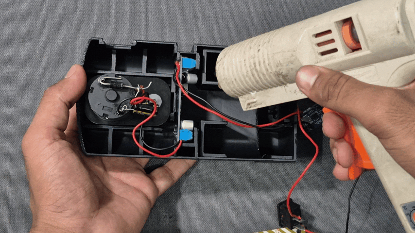
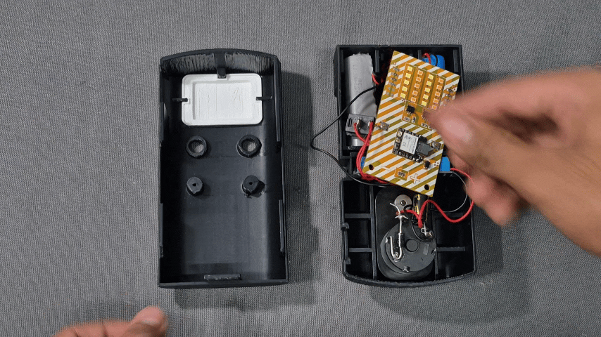
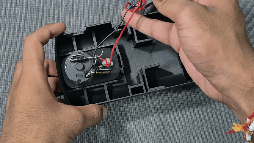
With all the electronics and 3D-printed parts ready, it was finally time to put everything together.
I started by installing the motor and hand-crank mechanism, followed by the batteries and the power management modules. The LED control PCB was then mounted in its dedicated position.
After connecting everything, I installed the diffuser and closed the enclosure.
This was probably the most satisfying part of the project, since all the individual components finally started looking like an actual finished product.
The Final Result
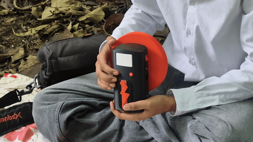
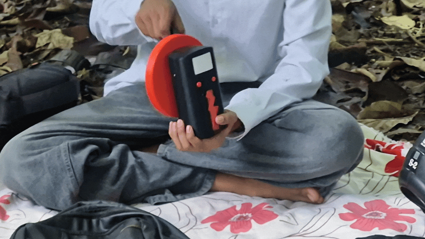
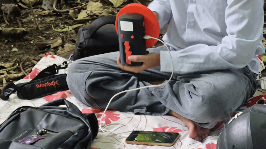
After putting everything together, RE:VOLT was finally complete.
The hand crank drives the DC geared motor, which generates electricity. The output then passes through the protection and filtering circuit before being regulated and sent to the battery charging circuit. The two 18650 batteries store the generated energy, while the built-in lamp provides both White and Warm White lighting.
The lamp can be controlled independently using the physical buttons or through the Wi-Fi web interface.
Of course, the project has a few limitations. The biggest one is the hand-crank generator itself. The output depends heavily on how fast the crank is rotated, and generating a meaningful amount of energy by hand takes time and effort. The current charging setup also isn't particularly fast.
In a future version, I would like to upgrade the USB charging module and improve the overall charging system to make the device more practical and efficient.
Still, this project was never meant to replace a conventional power bank. I mostly wanted to combine power generation, battery charging, embedded electronics, mechanical design, and 3D printing into one device that actually looked and worked like a finished product.
And honestly, I'm pretty happy with how RE:VOLT turned out.