High Resolution Ticker & Video LED Panels
by illusionmanager in Workshop > Home Theater
1412 Views, 10 Favorites, 0 Comments
High Resolution Ticker & Video LED Panels

Get ready for another instructable by illusionmanager!
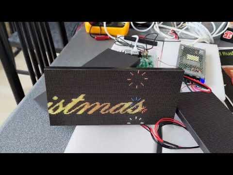
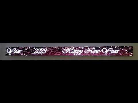
Prepare to be amazed as I guide you through the exciting process of connecting pre-made parts to create a jaw-dropping, high-resolution LED display boasting a whopping 896x64 pixels. With this many pixels, get ready to witness text scrolling with unparalleled clarity and quality. We're talking about a P2 display here, folks! Every 2mm, there's a brilliant LED shining brightly, making it perfect for those short viewing distances where you want nothing but perfection.
But wait, it gets even better! The chosen controller for this project is asynchronous, which means it operates independently without the need for a connected computer. How cool is that? All you have to do is download your desired text or video using its WiFi connection, and voila! You're ready to start displaying your captivating content. The app accompanying the display gives you full control, allowing you to select which program to run, adjust the brightness levels, and so much more.
Speaking of brightness, let me tell you, it's absolutely phenomenal! This display shines with such brilliance that it easily holds its own even in broad daylight. Normally, I keep it running at a modest 25% of its maximum brightness, and it still blows me away! So get ready to experience the future of LED displays, my friends. You won't believe your eyes when you see the stunning results of this project. Let's dive in and make magic happen!
Supplies

4 pcs P2 Indoor LED Module 256*128mm
3 pcs P2 Indoor LED Module 256*128mm and power supply
Huidu HD-C16C WIFI Asynchronous LED Video Display Card
5 Meters 1.27mm PITCH color Flat Ribbon Cable 16P
2 * 10PCS 2.54MM Pitch 16Pin Female Connector
2 * aluminum angle 30x15mm 1792mm long (from your local shop)
16 * short M3 bolts (to mount the panels)
2 * 40mm M4 bolts and 6 M4 nuts
some not-too-thin electric wire, a wire divider and a power plug.
some double sided tape.
Measuring and Drilling


Get ready for a straightforward construction approach that I've devised! Here's the scoop: Grab two aluminum angle pieces and securely screw the panels onto them. The brilliance of this setup lies in the 30mm long side of the aluminum angle, providing ample room to cleverly conceal the controller, power supply, and WiFi antenna. So, let's dive in and start measuring to determine the precise drilling positions for mounting the panels.
Now, pay close attention to this next step. I strived for impeccable precision during my own project, as any slight deviation in drilling accuracy becomes glaringly noticeable when the display is turned on, revealing visible seams between the panels. To tackle this, I made the holes slightly larger, allowing for a bit of flexibility to adjust the display. However, exercise extreme caution when handling the panels, especially along the edges where the delicate LEDs reside, as they can be easily damaged.
Apart from the 3mm holes required for panel mounting, you'll also need to incorporate additional holes to accommodate the small black protrusions present on each panel. While it's possible to remove these protrusions, opting to drill a few extra holes proves to be a simpler solution.
Before we proceed, take a moment to peruse the rest of the instructable. Familiarize yourself with the ideal position for the power supply. The plan is to suspend the power supply from the top aluminum angle using two M4 bolts. Once you've identified a suitable location, determine the corresponding drill points for the holes. Oh, and don't forget about ventilation! It's essential to ensure proper airflow, so remember to drill some additional holes in both the top and bottom aluminum angles.
With this knowledge at your disposal, you're well-equipped to bring this project to life. Get ready for an impressive display as we roll up our sleeves and set the tools in motion!
Mounting the Panels

Let's get those M3 bolts ready to mount all the panels! Begin by focusing on the central panel. Position it first and then move on to the next one, placing it to the right of the central panel at a slight distance. With a gentle touch, slide it to the left until it snugly aligns with the central panel. Repeat this process for the panel to the left of the central one and continue until you have successfully mounted all seven panels.
Now, pay close attention to this crucial detail: ensure that all the panels are mounted in the same orientation, with the arrows pointing upwards. Maintaining consistency in their alignment is key to achieving the desired outcome.
Adding WiFi

Typically, WiFi signals (or any radio signals) aren't particularly fond of metal. To overcome this hurdle, I strategically positioned the WiFi antenna along the edge of the display. Thankfully, it comes equipped with double-sided tape, making the mounting process a breeze and can effortlessly secure the antenna in place and ensure optimal signal reception.
Mounting the Controller

To ensure a balanced weight distribution for the display, I made a deliberate choice. The controller was positioned on one side, specifically the side nearest to the WiFi antenna, while the power supply was placed on the other side. In order to minimize cable length and maintain a neat appearance, I opted to mount them closer to the center of the display.
To address any potential electrical issues that could arise from the controller coming into contact with the metal surface, I applied insulation tape to the aluminum angle, creating a protective barrier.
The controller was position between the power connector and the 16-pin data connector on a panel, providing a precise fit. To secure the controller in its designated position, I employed double-sided tape.
Mounting the Power Supply

To securely mount the power supply to the top aluminum angle, you will need two M4 bolts and some nuts. When attaching the power supply, it is crucial to consider its positioning. Make sure to place it in such a way that the connectors on the panels remain easily accessible.
Connecting the Panels
To establish the connections between the panels and the controller, utilize the 16P flat ribbon cable. It is crucial to connect the panels in the correct order, from panel 1 through panel 7, from left to right, and attach them to the right connector on the controller. Begin by cutting the cable to the appropriate length for panel 1. It's advisable to leave a bit of extra length to accommodate going around the power supply and allow for a bend around the plug on one end.
It's important to note that each panel has two data connectors, but we will only be using the one marked as input. Attach 16-pin female plugs to the cable for each panel. A vice can be useful in firmly pressing the plugs into place. Repeat this process for all the other panels, ensuring a secure and reliable connection for each.
Powering the Panels
Given the considerable power consumption of this LED setup, it's essential to utilize thicker cables when connecting each panel to the power supply. To distribute power effectively, I employed a wire splitter near the controller. This allowed me to supply power to the panels in close proximity. When making the connections, be mindful to match the positive and ground outputs of the power supply to the corresponding pins on each panel.
On the other end of the power supply, you'll naturally need to establish a connection to your mains power source. To achieve this, make use of a power plug and a sufficiently long cable.
Remember, prioritizing safety and ensuring proper power distribution is crucial when dealing with high-power LED displays. Take the necessary precautions and double-check your connections to create a secure and efficient setup.
Software


Get ready to dive into the exciting world of LED displays! Start by downloading the essential software, HDplayer and HDset. Although it has been some time since I initially set it up, I recall the process being relatively straightforward. Don't worry, you'll have no trouble getting everything up and running smoothly.
For seamless connectivity, consider configuring your router to assign a static IP address to the device. This ensures that the app on your phone can easily locate and connect to it whenever needed.
Once you have the software ready, use HDplayer to create your first captivating program. Whether it's a mesmerizing movie or eye-catching scrolling text, let your creativity flow. When you're satisfied with your creation, simply hit the send button to upload the data to the controller. The magic begins as your program comes to life on the LED display!
As you develop more programs, the app comes in handy for selecting your desired display content. Feel free to create playlists or switch between programs effortlessly using the app's intuitive interface.
Now, it's time to sit back, relax, and marvel at the brilliance of your LED display. Enjoy the captivating visuals and the endless possibilities it brings to your environment. Let your imagination run wild and make the most of this exciting technology!


As you can see from this video, I made this already some time ago. Although I might have overlooked a detail or two, I trust that there's ample inspiration for you to embark on crafting one yourself. It isn't that hard once you have the right components.
(any artifacts you see are due to inteference with camera pixelation causing moire patterns and interference with camera shutter speed, causing some parts have different brightness. In reality it looks just stunning)