Home Automation With a Smartphone (TV, Arduino, Light, Security, Projector, DVD Player...)
by Imetomi in Circuits > Arduino
63617 Views, 800 Favorites, 0 Comments
Home Automation With a Smartphone (TV, Arduino, Light, Security, Projector, DVD Player...)


These days the home automation devices and the home controlling systems are very popular. Even in the community of DIY-ers. So decided to make my own home control device using Arduino. The device can be controlled with a cellphone, and here I used a very odd/wierd mode to transmit the commands from the phone. I used an INFRARED blaster to control my household items, like the TV, music amplifier, light switch, motion sensor alarm system. But this technology is also able to control almost any infrared gadgets gratitude for the ZaZa Remote app. Lot of smarphones have infrared blaster, but my one hasn't, so I needed to make one that can be attached to the audio jack. This was very simple and doesn't costs more than 0.5 bucks.
And yes, you could ask now that why am I using IR (infrared) and no Bluetooth or Wifi?
The answer is easy: -Usually the remote controlled household items can be controlled by an infrared transmitters, like music amplifiers, TVs, air conditioneers, digital photo frames, R/C toys, DVD players, switches, camera triggers and more. Now imagine that you can connect to these with your phone and control with only one device.
-It's easier to write the code on the Arduino, and it's cheaper than Bluetooth. You'll need some experience in Arduino, but I think that even a beginner can make.
What Is IR Light?
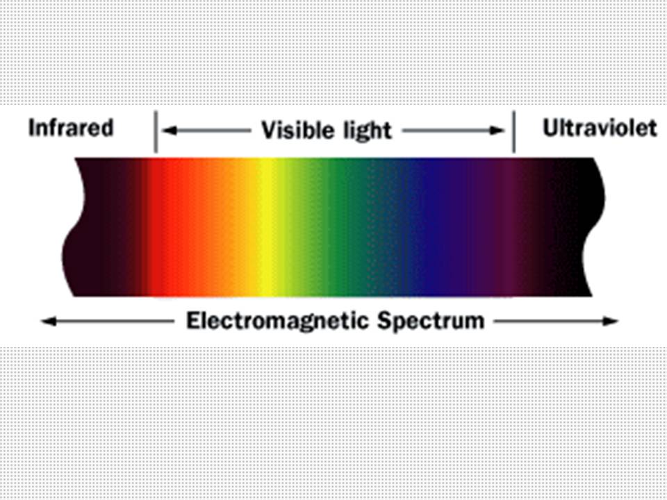
Infrared (IR) is invisible radiant energy, electromagnetic radiation with longerwavelengths than those of visible light, extending from the nominal red edge of thevisible spectrum at 700 nanometers (frequency 430 THz) to 1 mm (300 GHz)(although people can see infrared up to at least 1050 nm in experiments. Most of the thermal radiation emitted by objects near room temperature is infrared. Thank you Wikipedia...
Build the Blaster


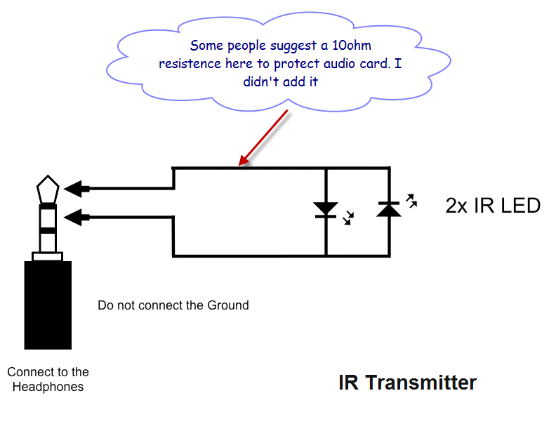
This is the easiest part of the project. You'll need 2 pieces of IR LEDs, a 3.5mm audio jack and some electrical tape. You can find these parts in the local Hobby-Shop. See the circuit diagram on the last picture and solder the LED pins to the left and right chanell. The GND isn't needed. If we solder the LEDs good we will have a very cool 38kHz infrared transmitter.
App Tutorial

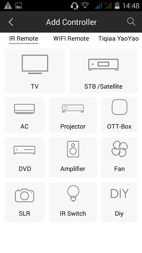
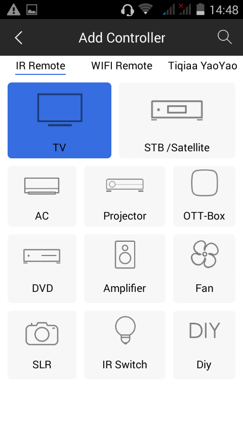
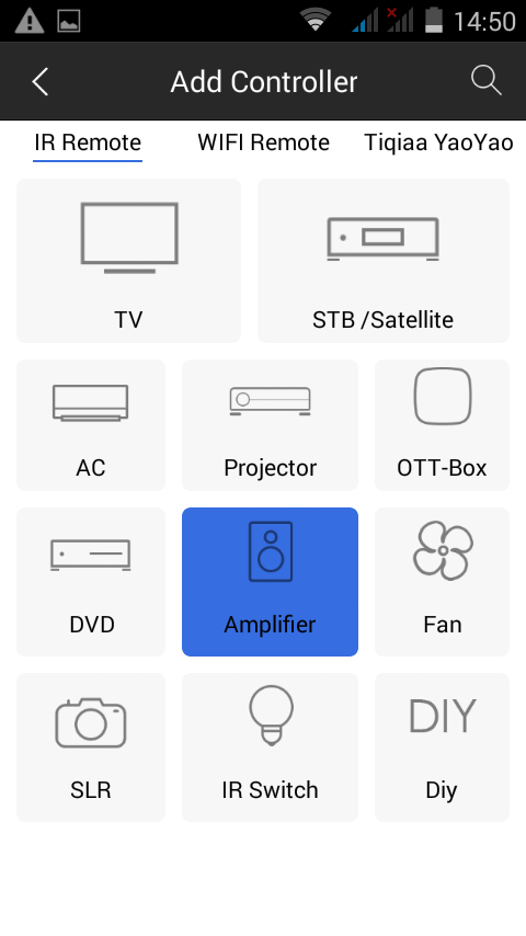
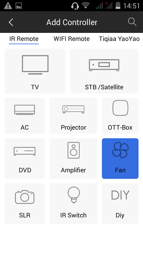
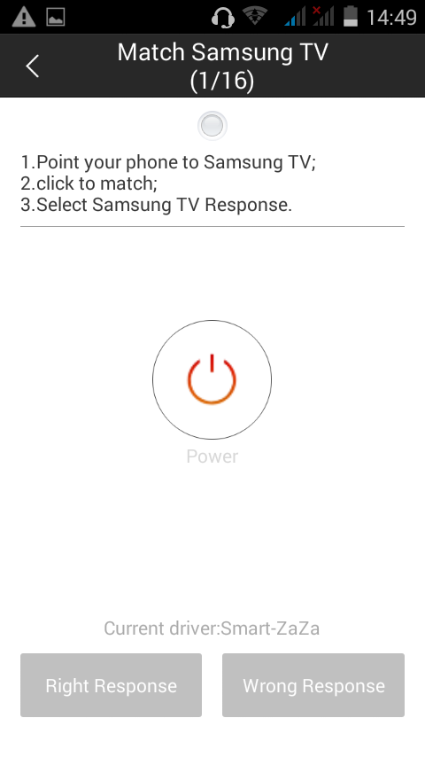
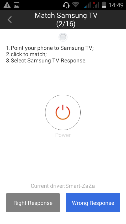
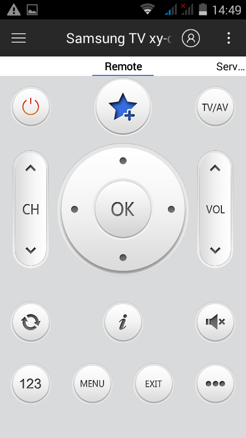
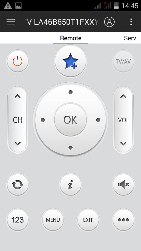


First Download the ZaZa Remote app on your phone or tablet (of course the project works even with other apps). Connect your new IR blaster, and you can see that here are a lot of possibilities, but we now will use the TV option. In the next step you will need to find the coding of your TV, this may take some minutes. After you found it you can use the phone to control the TV. I can't take a good photo about it but works. Now I'll show you how to send these commands to the Arduino.
Decoding the Signals


#include <IRremote.h>
int RECV_PIN = 11;
IRrecv irrecv(RECV_PIN);
decode_results results;
void setup()
{
Serial.begin(9600);
irrecv.enableIRIn(); // Start the receiver
}void loop() {
if (irrecv.decode(&results)) {
Serial.println(results.value, HEX);
irrecv.resume(); // Receive the next value
}
}
Decoding


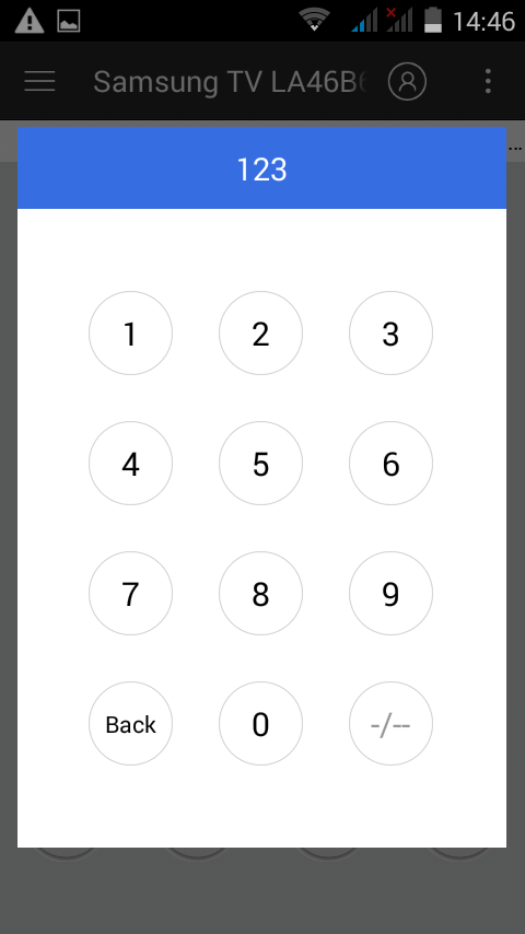
Load up this code on your Arduino board and open the Serial Monitor and write every important codes. I wrote numbers, volume and chanell buttons and the power button.
Parts and Materials for the Arduino Circuit


First of all your CREATIVITY!
- an Arduino Board
- a smartphone
- a plastic box
- a PIR sensor
- 2x 220 ohms resistors
- a buzzer
- a breadboard
- a 38kHz IR reciever
- an LED
- a 5v relay
- and some wires
I haven't time now to build a better circuit, that can control more things, because the Phone Contest closes soon, But if you use your creativity you can build anything (RC toys, drones, robots...)
Test the PIR


I tested my PIR sensor because if has problems can damage the 3rd pin on my Arduino, but worked perfect. I just used a 9 volt battery and an LED.
Build the Circuit


I use an extension board because it's easier to build the curcuit with it.
- Connect the relay to the pin 6 and to the VCC and to the GND
- Connect the IR sensor to the GND, VCC and to the pin 11.
- Connect the PIR sensor also to the GND, VCC and to the pin 3.
- The LED is connected to pin 13.
- And lastly connect the buzzer through a 220 ohm resistor to the pin 9.
Yes, I said the Arduino part is easy. This is to inspire to make you to make something mindblowing device.
Write the Code!


Download the Arduino file, load up and now you can try it out. If you have any question about the code feel free to ask. Replace the IR signal decoding with yours, example 0x0E0E005A.
Downloads
Testing


I programmed the PIR on/off switch to the 1 and 2 pins. Well actually it's not a switch, only sets the pin 3 as an INPUT, and reads the signals (HIGH or LOW), and turns on the buzzer for 15 seconds. This is a very basic motion sensor alarm. The relay can be switched ON and OFF with the up and down arrows.
Drilling Holes for the Cables


Use a rotary tool or a drill, and make 2 holes for the USB cable and for light's cable.
Prepare the Cables


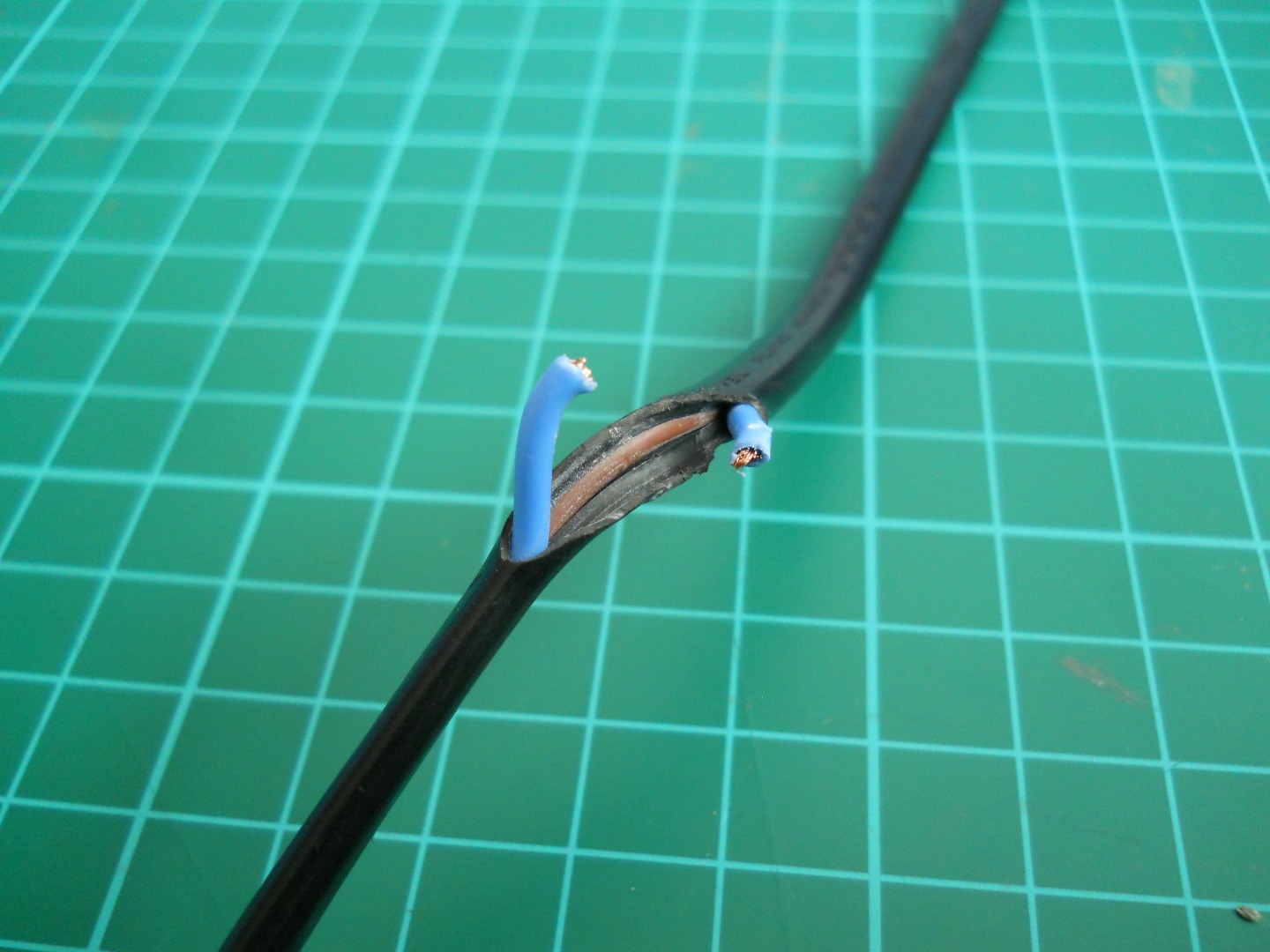


Clean the plastic cover then remove the cover from one of the wires. Then fix it with electrical tape. Just like on the pictures. For the power supply I'll use a a 5v 1A phone charger.
Connecting the Cables


Use a screwdriver and connect your light's cable to the relay module. Of course can connect other devices. :)
Search a Good Place for It!


If you found the best place for the box connect power up the device and test it agian.
The Last Test


