Home Humidity Control
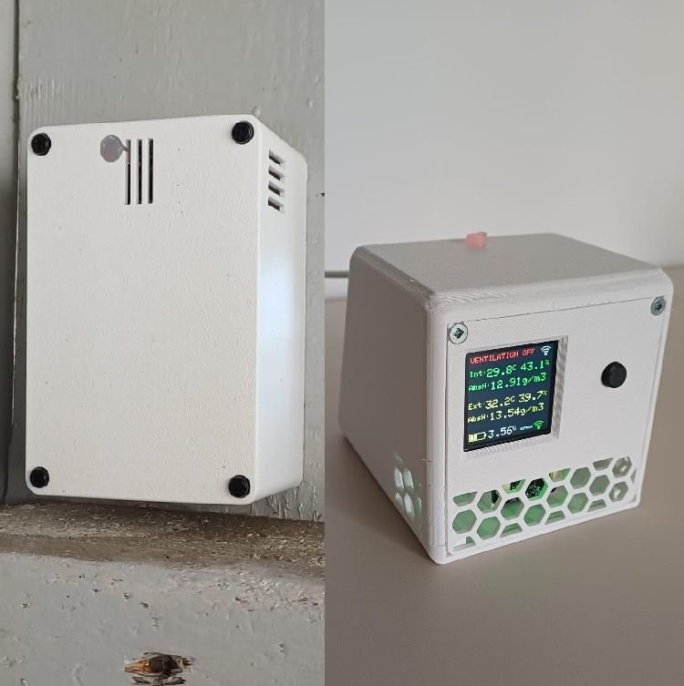
Do you struggle with high humidity and mold in your home? Opening the windows or turning on a ventilation fan seems like the obvious answer, but there is a catch: if it is raining or highly humid outside, you might actually be bringing more moisture into your house!
This project solves that problem. We are building a Smart VMC (Controlled Mechanical Ventilation) system that acts as a "humidity gatekeeper." It uses two high-precision sensors (one inside, one outside) to calculate the exact amount of water in the air. It will only turn on your ventilation system when the outside air is actually drier than the inside air.
Plus, it features a beautiful color display, an onboard RGB LED status indicator, and connects to your smartphone via the Blynk IoT platform for live charts and push notifications!
Supplies
Indoor Unit:
- No.1 DFRobot FireBeetle 2 ESP32-E
- No.1 SHT45 Sensor
- No.1 1.54" TFT Display (ST7789)
- No.1 Push Button
- No.1 USB-C Power Supply
- Lot Jumper Wires & Breadboard
Outdoor Unit
- No.1 DFRobot FireBeetle 2 ESP32-C6
- No.1 SHT45 Sensor PTFE
- No.1 16340 Li-ion Battery & Holder
The Architecture: ESP-NOW + Wi-Fi Coexistence
To make this work without running wires through your walls, we use two ESP32 microcontrollers:
- The Outdoor Unit: Runs on a battery. It wakes up every few minutes, reads the weather, and shoots a fast radio message to the Indoor Unit using a direct protocol called ESP-NOW. Then, it goes back to deep sleep to save power.
- The Indoor Unit: Plugged into the wall. It acts as a bridge. It listens for the ESP-NOW radio messages from the outdoor unit, while simultaneously maintaining a standard Wi-Fi connection to your home router to send data to the Blynk Cloud.
The Theory: Relative Vs. Absolute Humidity
Most standard weather stations only show Relative Humidity (RH), measured in %. But RH is tricky because it changes based on temperature. Warm air can hold a lot more water than cold air.
Imagine it's a cold winter day:
- Inside: 20°C with 60% RH.
- Outside: 5°C with 90% RH.
If you look at the %, you might think: "I shouldn't open the window, it's 90% humid outside!" But here is where Absolute Humidity (AH) comes in. AH measures the actual weight of water in the air (grams per cubic meter, g/m³), regardless of temperature.
- Inside AH: ~10.4 g/m³
- Outside AH: ~6.1 g/m³
Even though the outside Relative Humidity is 90%, the actual amount of water in the air is much lower! Our ESP32 brain does this complex math in real-time, ensuring your ventilation only runs when it's physically beneficial.
Smart Logic: Hysteresis & the RGB LED
If the indoor humidity is 10.0 g/m³ and the outside is 9.9 g/m³, the system should turn on. But if a slight breeze changes the outside to 10.1 a second later, it would turn off. This rapid ON/OFF switching is called the "ping-pong effect" and it can damage relays and fans.
To prevent this, the code uses a 2.0 g/m³ Hysteresis threshold.
- To turn ON, the outside air must be significantly drier (at least 2.0 g/m³ lower than inside).
- Once running, it will stay ON until the outside air becomes equally or more humid than the inside, turning OFF immediately.
You can monitor this behavior via the Onboard RGB LED on the Indoor FireBeetle board:
- 🔵 Blue (Solid): System is starting up and currently connecting to your Wi-Fi network.
- 🟢 Green: Ventilation ON. Outside air is perfect.
- 🟡 Yellow: Ventilation OFF, but waiting. Outside air is drier than inside, but hasn't reached the 2.0 g/m³ threshold gap yet.
- 🔴 Red: Ventilation OFF. Outside air is worse than inside, or the outdoor unit is disconnected.
Hardware Connections
Indoor Unit (FireBeetle 2 ESP32-E)
⚠️ IMPORTANT NOTE ON GND & 3.3V CONNECTIONS: The Indoor Unit requires more GND and 3.3V connections than the board has physically available on its pins. You will need to create a multiple junction (using a breadboard, Wago splicing connectors, or by soldering wires together) to connect all the components properly to a single power and ground source.
Setting Up Blynk IoT Platform
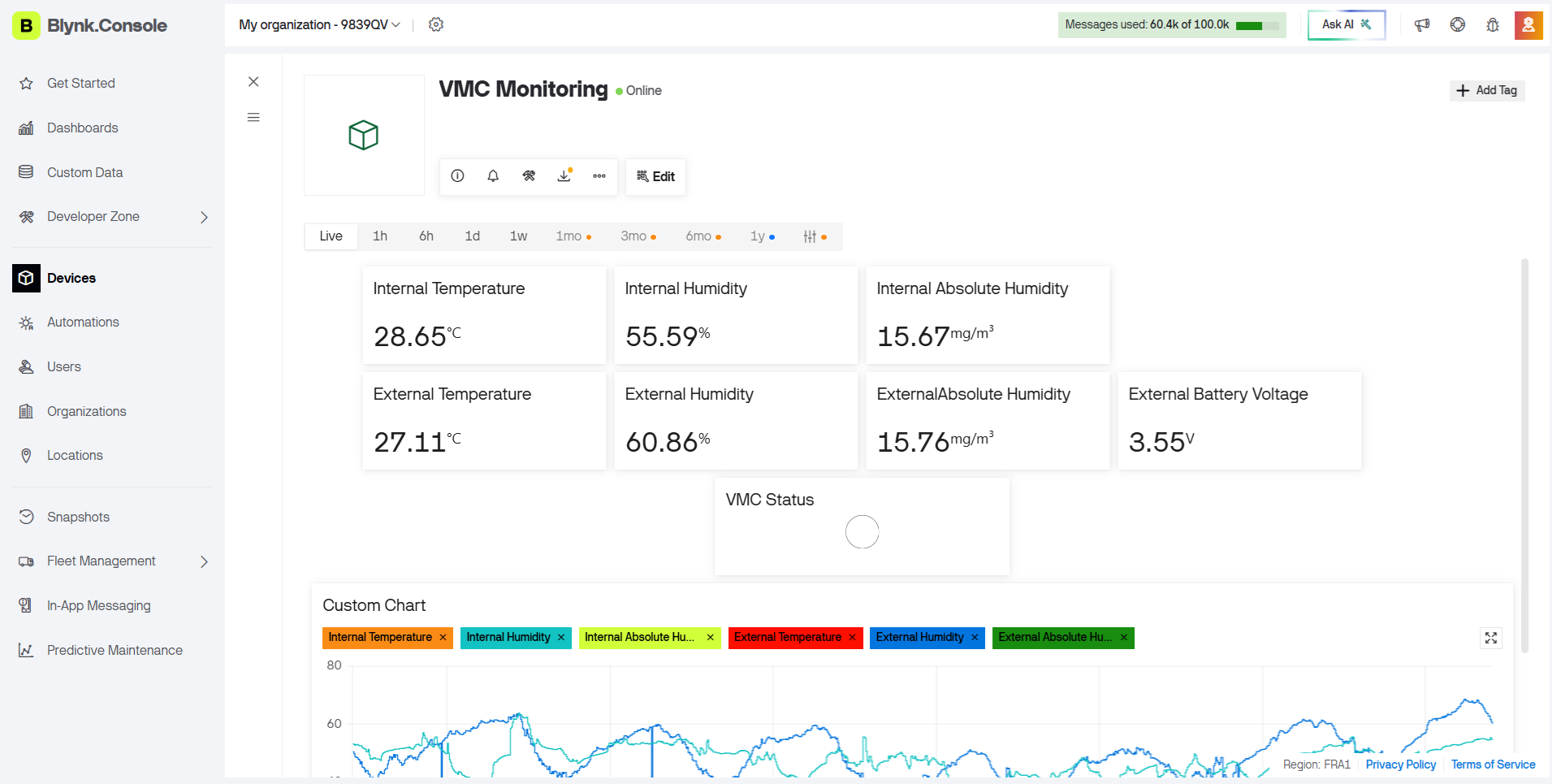
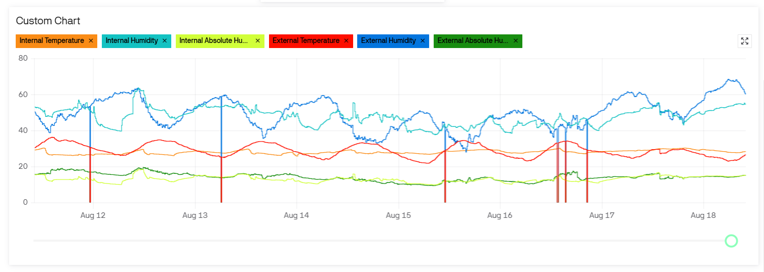
We will use Blynk to see our data anywhere in the world and store it in beautiful charts, as well as get push notifications on our phones.
- Go to blynk.cloud and create a free account.
- Go to Developer Zone (Templates) and click + New Template. Name it "VMC Controller", Hardware "ESP32", Connection "WiFi".
- Go to the Datastreams tab and create these 8 Virtual Pins (Type Double/Float, except V7 which is Integer):
- V0 : Indoor Temp (°C)
- V1 : Indoor Hum (%)
- V2 : Indoor Abs Hum (g/m³)
- V3 : Outdoor Temp (°C)
- V4 : Outdoor Hum (%)
- V5 : Outdoor Abs Hum (g/m³)
- V6 : Outdoor Battery (V)
- V7 : VMC Status (0 to 1)
- ⚠️ CRITICAL STEP FOR CHARTS: To make the historical charts work properly, click on the History tab (or advanced settings) for each Datastream and select "1 minute AVG" (or another average interval) under the Save data to Time Series setting.
- 📲 SETTING UP NOTIFICATIONS: Go to the Events tab in your Template. Click + Add New Event. Set the Event Name and Event Code to vmc_status. Under the Notifications tab of this event, enable "Push Notifications to app".
- Go to Search -> Devices -> + New Device -> From Template.
- Copy the TEMPLATE_ID, TEMPLATE_NAME, and AUTH_TOKEN provided. You will paste these into the Arduino code!
- Smartphone App: Download the Blynk IoT app on iOS or Android. Log in, and you will see your device! You can build a mobile dashboard and you will now receive push notifications whenever the VMC turns ON or OFF.
Software Preparation
You need to install these libraries via the Arduino Library Manager:
- Sensirion I2C SHT4x
- TFT_eSPI (By Bodmer)
- Adafruit NeoPixel (For the onboard RGB LED)
- Blynk
Important TFT Display fix: After installing TFT_eSPI, you must go to your Arduino libraries/TFT_eSPI folder, open User_Setup.h, comment out the ILI9341 driver, and uncomment #define ST7789_DRIVER. Also, set your specific ESP32-E pins in that file (TFT_MOSI 23, TFT_SCLK 18, TFT_CS 0, TFT_DC 25, TFT_RST 14)
The Code
Upload the Outdoor code to your ESP32-C6. Then, paste your Wi-Fi credentials and Blynk Tokens into the Indoor code and upload it to the ESP32-E.
Make sure to change the MAC Address in the outdoor unit code to match the MAC address of your indoor unit!
(See attached .ino files for the complete code).
NEXT UPDATE
Up to now the system requires a manual operation to switch ON and OFF the ventilation system, in the future is possible to make and automation between the system indication and the phisical ventilation device
3D File
Check the .stp file in order to 3d print the enclosures. Both enclosures have a phisical separation between the Temperature and humidity sensor and the elctronic part in order to avoid to measure the heating of the electronic parts. LED indication is made with a hot glue stick cutted to measure that act as a light path and shows outside the color of the led.