How to Build a Stairbot With Makeblock
by Makeblock Robotics in Circuits > Arduino
4872 Views, 49 Favorites, 0 Comments
How to Build a Stairbot With Makeblock
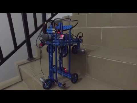
Recently, we just hit upon a great idea that we can build a car which climbs stairs automatically.
Now let’s introduce the building steps of this car. Line follower (used as a contact switch), ultrasonic sensor, limit switch, gyroscope, all kinds of sensors used in building this car is to ensure that it can climb stairs automatically.
All the parts are from: www.makeblock.com


First of all, we would like to walk you through the working principle of this case. In general, there are 8 stages in this case under ideal condition. Wheel 1 and wheel 4 are driving wheels equipped with motors, while the others are driven wheels. The lifting devices are installed separately on wheel 2 and wheel 4.
Stage 1
The car goes forward.
Stage 2
The ultrasonic sensor has detected the obstacles in front.
Then lifting devices on this car will lift wheel 1 and wheel 3 up until the ultrasonic sensor can’t detect obstacles.
Note: “obstacles” here refers to “stairs”.
Stage3
The car keeps moving forward, driven by wheel 1 and wheel 4.
Stage 4
As showed in the picture, the line follower on wheel 2 has detected obstacles (the stairs), so lifting device 1 will lift the wheel 2 up to the next higher stair.
Stage 5
The car keeps moving forward, driven by wheel 1 and wheel 4
Stage 6
The driving wheels (wheel 1 and wheel 4) will automatically stop when the limit switch on wheel 4 has detected the stairs. Lifting device 2 will then lift wheel 4 up.
Stage 7
The car continues moving forward, driven by wheel 1
It’s like we go back to stage 1 again...
Stage 8
Stage 8, the same as stage 2. The robot car keeps moving forward until the ultrasonic sensor detects the obstacles...
Generally, in this case, the working principle cycles from stage 1 to stage 8.
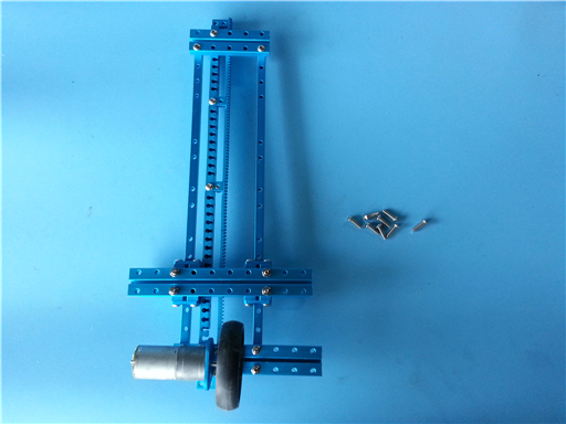
From the perspective of mechanical structure, the unique part of this case is the design of lifting device which is required to be both reliable and rapid when lifting things up and down.So in this case, we used gear and rack to build lifting devices. As showed in the following description, we used beam 0808 to build a sliding track, and a belt connector connected with a beam 0824 to build a simple sliding block.


Next is the parts used in each step and the building method. Lifting device 1
Part List:
4 x Beam0824-032
2 x Beam0824-160
8 x Screw M4x22
8 x Nut M4
Use the following parts to connect the structure.


Part List:
4 x Belt Connector
16 x Screw M4x8
Just by simply tightening the screws, we can building a sliding block easily.
Grab two Beam0808-312 which can go through the sliding block right away.


Now let’s move to the next step: building the rack.
To make sure this intelligent auto stair-climbing car to adapt stairs of different height, the sliding track and the rack should be long enough. The sliding track is 312mm long, thus the rack should not be short
All we need to do is connect 4 sections to build the rack. The reason why we used a Beam0808-312 here is to prevent the joint of rack sections from bending during lifting process. If the joint of rack section bends, there will be meshing problem between the gear and the rack. Therefore, we should fix the rack onto Beam0808-312, as showed in following picture:

Connect the guide rail and the rack
Part List:
1 x Beam0824-144
3 x Screw M4x22
2 x Nut M4


Part List:
2 x Beam0824-176
6 x Screw M4 x 22
6 x Nut M4


Install wheel 2 (engaged wheel)
Part List:
2 x Tyre 64*16mm
2 x Timing Pulley 90T
2 x Threaded Shaft 4x39mm
4 x Flange Bearing
2 x Screw M4
2 x Headless Set Screw M3x5
4 x Plastic Spacer4x7x2
Fix two tyres on two ends of the Beam0824
Following all the steps, we finished assembling wheel 2 and lifting device 1.


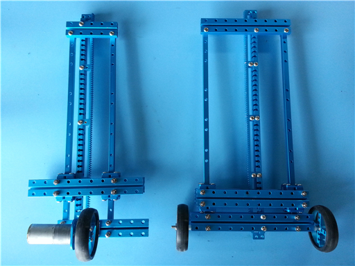
Let’s get you across to the next step--assemble wheel 4 and lifting device 2.
The structure of lifting device 2 is the same as lifting device 1, so as the parts used for assembling.
The only difference is you need to fix the Beam 0824-032 as showed in the picture.
Assemble the guide rail and the rack same as the steps of building lifting device 1.Use Beam0824-080, instead of Beam0824-144, to connect the upper end.


To connect the lower end, we use the following part:
1 x Beam0824-128
6 x Screw M4x22
6 x Nut M4


Install Bracket L1 on Beam0824
Part List:
2 x Screw M4x14
2 x Nut M4


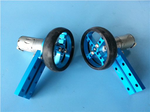
After finishing building lifting device 2, we can start building wheel 4 (driving wheel)
Part List:
1 x DC Motor-25
1 x Timing Pulley 90T
1 x DC Motor-25 Bracket
1 x Shaft Connector
1 x Headless Set Screw M3x5
2 x Screw M4x14

Install tyres
2 x Screw M4x14
2 x Nut
Install the above structure on Bracket L1
Until now, we finished building a half of this car.


The next step is to build main structure of the car and wheel 1 and wheel 3.
Build wheel 1 (driving wheel) first.
2 x Tyre 64*16mm
2 x Timing Pulley 90T
2 x Shaft Connector
8 x Screw M4x14
4 x Nut M4
4 x Screw M3x5
4 x Headless Set Screw M3x5
2 x DC Motor-25mm
2 x DC Motor-25 Bracket
2 x Beam0824-064


Assemble anti-collision bar
Part list:
1 x Beam0824-160
2 x Bracket L1
4 x Screw M4x14
4 x Nut M4


Assemble main structure of the car
Part List:
2 x Beam0824-192
1 x Anti-Collision Bar
2 x Tyre 64*16mm
6 x Screw M4x30
6 x Nut M4

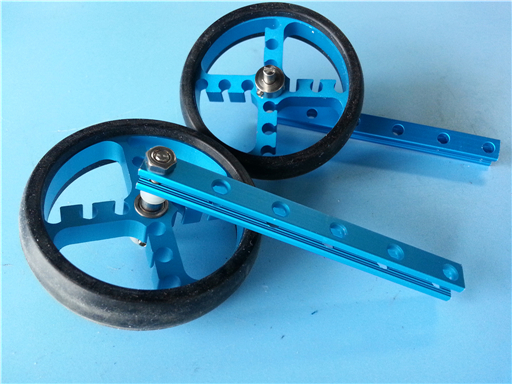
Assemble wheel 3 (driven wheel)
Part List:
2 x Tyre 64*16mm
2 x Timing Pulley 90T
2 x Beam0808-088
4 x Flange Bearing
2 x Threaded Shaft
4 x Plastic Spacer4x7x2
2 x Nut
2 x Headless Set Screw M3x5


Part List:
4 x Screw M4x22
4 x Nut M4
Fix wheel 3 onto the car bracket

Install lifting device 2 on the car bracket
Part List:
8 x Screw M4x14


Use 6 Screw M4x14 to install fting device 1
The width of the stairs is
limited and tyres are too big, so we had to stagger the positions of all the tyres. In wheel 4, we only used a motor and a tyre.


Install the motor of lifting device
Part List:
2 x DC Motor-37
2 x Gear 18T
2 x Headless Set Screw M3 x 5
4 x Screw M4 x 8
Note: Before installing DC Motor-37, assemble the motor bracket first.
Adjust the distance between the gear and the rack, then fix the motors separately in the thread groove of Beam0824 on lifting device 1 and 2
Step by step, we finished building the whole mechanical structure of this car.


Let’s move on to the next step—install sensors
1 x Limit Switch
Install the limit switch on the side of lifting device 2
2 x Limit Switch
Install these two limit switch separately on beams of lifting device 1 and 2.
Note: the limit switch is used to limit the lifting height.


Install line follower sensor
Part List:
2 x Screw M4 x 22
2 x Plastic Spacer 4*7*10
4 x Plastic Spacer4x7x2
1 x Me Line Follower

Install gyroscope


Install ultrasonic sensor
As we all know, the ultrasonic sensor can’t detect obstacle in distance of 0-30mm. So in this case, we installed the ultrasonic sensor inside the car, letting the anti-collision bar in front to crash the stairs. In this way, the ultrasonic just happen to be able to detect obstacles-- stairs.


Install Me Orion


Install adapter (for limit switch)

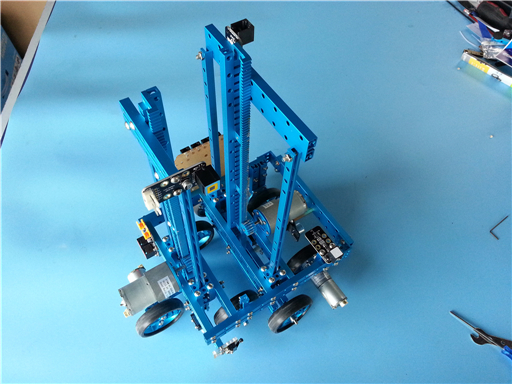
Finishing installing all the sensors, now let us take a look at the whole structure of the car and the sensors
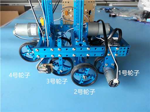
This car can be divided into 4 parts based on the number of tyres.
Wheel 1 and wheel 4 are driving wheels, while wheel 2 and wheel 3 are driven wheels
( Wheel 4 Wheel 3 Wheel 2 Wheel 1)
In this car, the lifting device1 and 2 control the position of wheel 2 and wheel 4
(Lifting device 1 Lifting device 2)
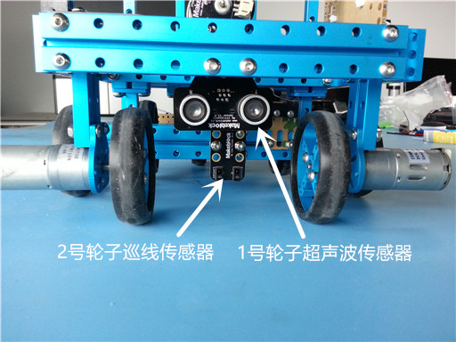
(Line follower of wheel 2 Ultrasonic sensor of wheel 1)
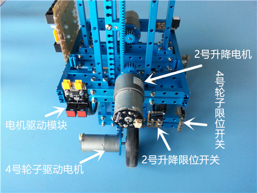
(Motor drive module Drive motor of wheel 4 Limit switch of lifting device 2 Limit switch of wheel 4 Lifting device 2)
(Gyroscope Drive motor of wheel 1 Lifting device 1 Drive motor of wheel 1 Limit switch of wheel 2)
Why we need a gyroscope? The gyroscope here is used to adjust the lifting speed of the motor, thus to balance the car itself (motors used in the lifting device are DC motor which fail to balance the car).


The whole car:

Wiring Map
[mw_shl_code=applescript,true]#include "MeOrion.h"
#include

MeGyro gyro;
MeDCMotor lifer1(PORT_1);  //升降1
MeDCMotor lifer2(PORT_2);  //升降2
MeDCMotor rw(M2);  //1号驱动轮
MeDCMotor fw(M1);  //4号驱动轮
MeLineFollower lineFinder1(PORT_7);  // 巡线
MeLimitSwitch upWard1(PORT_3, SLOT2);  // 1号升降限位开关
MeLimitSwitch forWard2(PORT_4, SLOT1);   // 4号轮子限位开关
MeLimitSwitch upWard2(PORT_4, SLOT2);  // 2号升降限位开关
MeUltrasonicSensor ultraSensor(PORT_8);  // 1号轮子超声波

void setup()  // 初始化,前后升降装置回收
{
  Serial.begin(9600);
  gyro.begin();
  lifer1.run(-250);
  while (!upWard1.touched());
  lifer1.stop();
  lifer2.run(-250);
  while (!upWard2.touched());
  lifer2.stop();
}


void Step2()
{
    float p = 15;
    float i = 0.01;
    float angle = 0;
    float targetAngle = 0;
    float integration = 0;
    float err = 0;

    while (NotStop())
    {
        gyro.update();
        float angle = gyro.getAngleX();
        err = angle - targetAngle;
        integration += err;

        int speed1 = 200;
        int speed2 = 200;

        speed2 = speed1 + err * p;// + integration * i;

        lifer1.run(speed1);
        lifer2.run(speed2);
        //delay(10);
    }
    lifer1.stop();
    lifer2.stop();
}

int startTiming = 0;
unsigned long startTime = 0;

int NotStop()
{
    int16_t distance;
    distance = ultraSensor.distanceCm();
    delay(10);
    if (0 == startTiming)
    {
        if ((distance < 10) && (distance > 1))
        {
            return 1;
        }
        else
        {
            startTiming = 1;
            startTime = millis();
            return 1;
        }
    }
    else
    {
        unsigned long currentTime = millis();
        if (currentTime - startTime < 2500)  //超声波检测不到楼梯后延时2.5秒
        {
            return 1;
        }
        else
        {
            return 0;
        }
    }
}


void loop()
{
  startTiming = 0;
  startTime = 0;
//阶段1 小车前进
  fw.run(60);
  rw.run(60);  //1号 4号轮子推动小车前进

  int16_t distance;
  do
  {
      distance = ultraSensor.distanceCm();
      delay(10);
  }
//阶段2 碰到楼梯 主动轮停止 整体车架上升
  while (!((distance < 4) && (distance > 1)));  //如果碰到楼梯

  fw.stop();
  rw.stop();
  Step2();
//阶段3 1号 4号轮子推动小车前进
  fw.run(60);
  rw.run(60);
//阶段4 2号轮子巡线传感器检测到楼梯 主动轮停止 升降装置1把2号轮子收回去
  while (!(lineFinder1.readSensors() != S1_IN_S2_IN));
  lifer1.run(-250);
  fw.stop();
  rw.stop();

  while (!upWard1.touched());  //1号升降限位开关检测升降结束
  lifer1.stop();

  Adjust();
//阶段5 1号 4号轮子推动小车前进
  fw.run(60);
  rw.run(60);
//阶段6 4号轮子限位开关检测到4号轮子碰到楼梯 主动轮停止 2号升降装置回收4号轮子
  while (!forWard2.touched());
  lifer2.run(-250);
  fw.stop();
  rw.stop();

  while (!upWard2.touched()); //1号升降限位开关检测升降结束
  lifer2.stop();
//阶段7 循环阶段1
//阶段8 循环阶段2
}

void Adjust() //陀螺仪控制1、2号升降电机控制平衡
{
    int p = 40;
    //float i = 0.05;
    float angle = 0;
    float targetAngle = 4;
    //float integration = 0;
    //float err = 0;

    do
    {
        gyro.update();
        angle = gyro.getAngleX();
        //err = (angle - targetAngle);
        //integration += err;
        lifer2.run((angle - targetAngle) * p);// + i * integration);
        //delay(10);
    }
    while(fabs(angle - targetAngle) > 1);

    lifer2.stop();
}

[/mw_shl_code]


Install motor drive Makeblock