How to Calibrate Your Board's ADC With Arduino Manager
by Fab64 in Circuits > Electronics
167 Views, 0 Favorites, 0 Comments
How to Calibrate Your Board's ADC With Arduino Manager
This tutorial explains how to use the new ADC calibration features available in Arduino Manager: Two-Point Calibration and Lookup Table Calibration.
Both techniques are designed to improve ADC accuracy and linearity, but their effectiveness depends on the characteristics of the ADC being used. In this tutorial, we'll examine how each method works, compare their results, and determine which approach is best suited for different types of ADC errors.
Before diving into the details, let’s start with a brief introduction to Arduino Manager.
Arduino Manager, is a powerful general purpose iOS iPadOS / watchOS / macOS App which allows to control any Arduino (or Arduino compatible) board by the means of about 40 different Widgets.
Some of the available Widgets are:
- Display Widget
- LED Widget
- Switch Widget
- Push Button Widget
- Knob Widget
- Slider Widget
- Alarm Widget
- Sound Alarm Widget
- Thermostat Widget
- Threshold Widget
- Text Widget
- and many more
Arduino Manager prioritizes your privacy, with no registration or cloud account required—only your Apple ID. However, you have the option to save your Widget Lists to iCloud, enabling seamless sharing across your devices.
For more information about Arduino Manager:
- Arduino Manager for iOS, Arduino Manager for macOS.
- Past Instructables:
- XXXXX
- How to Control Arduino R4 WiFi From Your IPhone / Apple Watch / IPad / Mac
- Cheap IOT Device in Minutes and Without Writing Any Code Using Raspberry Pico Pi W
- Controlling ESP32 Running Micropython With Arduino Manager
- Arduino Manager: Generate Raspberry Pi Pico C/C++ Code for an AC Power Monitor – Step-by-Step Example
- How to Measure a Remote Temperature Using Pico W and Arduino Manager
When the complexity of the Arduino code increases, such as when dealing with multiple analog and digital sensors to read, controlling numerous actuators, and implementing complex algorithms, the likelihood of making errors rises. Consequently, debugging the code becomes more challenging and the time and effort required to address these issues could significantly affect the progress of your project. For this reason Arduino Manager also provides (for an additional small fee):
- Code Generator: This add-on allows to generate the basic Arduino code for supporting the Widgets you need in your project.
- PIN Code Generator: Linking widgets to Arduino PINs, this add-on dramatically speeds up Arduino code development. In many cases you don't need to write a single line of code.
A nice additional feature is Voice Commands which allows to control most of the Arduino Manager Widgets by means of your voice (English and Italian only)!. See past Instructables form more.
Apple Watch is supported as well (with some limitations): you can control any Arduino board directly from your wrist, wherever you are in the world!
Arduino Manager for iOS/iPadOS is available here: App Store for $7.99 and includes the watchOS version. The macOS version is available here: App Store for $10.99 (please, note that not all the widgets are available on all the platforms).
More information, documentation, video tutorials, libraries and examples on Arduino Manager are available here:
Arduino Manager for iOS or here: Arduino Manager for macOS.
For this Instructable you need Arduino Manager version 24.4.0 or greater.
Supplies
- Raspberry Pi Pico W (Pico 2W will also work)
- Seeed Studio XIAO ESP32S3 (any other ESP32 board will also work)
- DAC: MCP4822 (any DAC will work, but you will need to adapt the provided code for your specific device)
- breadboard
- Jump Wires
- DMM (the more accurate the measurement, the better the calibration results will be)
- Arduino Manager
- Arduino Manger Code Generator
- Arduino Manger Pin Code Generator
What Is an ADC a What Are Its Source of Errors
An Analog-to-Digital Converter (ADC) is a device that converts a continuous analog voltage into a discrete digital value that can be processed by a microcontroller or computer. In simple terms, it translates real-world signals—such as voltage from a sensor—into numbers that digital systems can understand.
An ideal ADC would produce a perfectly linear relationship between the input voltage and the output digital code. In practice, however, real ADCs are affected by several types of errors that limit their accuracy and resolution.
Sources of ADC Errors
1. Offset Error
Offset error occurs when the ADC does not output zero for zero input. This introduces a constant shift across the entire transfer curve.
2. Gain Error
Gain error is a scaling error that affects the slope of the conversion curve. Even if the ADC is linear, the full-scale value may not match the expected value.
3. Non-Linearity (INL/DNL)
- Integral Non-Linearity (INL) describes how far the ADC transfer function deviates from a straight line.
- Differential Non-Linearity (DNL) describes irregular spacing between adjacent digital codes and can lead to missing codes in extreme cases.
4. Quantization Error
Since an ADC has finite resolution, each digital output represents a range of input voltages. This introduces an unavoidable rounding error of up to ±½ LSB.
5. Noise
Thermal noise, power supply noise, and digital switching noise inside the microcontroller can cause random fluctuations in the measured value.
6. Temperature Drift
ADC characteristics change with temperature, affecting both offset and gain over time.
Understanding these error sources is essential when working with real-world measurements, especially when high precision is required. The calibration techniques presented in this tutorial—Lookup Table and Two-Point Calibration—are designed to compensate for some of these imperfections and improve measurement accuracy.
This Instructable shows how Arduino Manager helps correct deterministic ADC errors—offset error, gain error, and non-linearity—using calibration techniques.
In contrast, noise is handled separately through sample averaging, which reduces its impact but does not eliminate it.
General Theory: Two-Points Calibration
Before diving into further details, a brief explanation of the techniques used.
Some mathematics is involved, but if you are not used to it, don’t worry—Arduino Manager handles most of the calculations for you automatically.
Two-point calibration is a simple method used to correct offset and gain errors in an ADC by measuring the system response at two known reference points.
The idea is straightforward: instead of assuming that the ADC transfer function is ideal, we measure how it actually behaves at two different known input values and use these measurements to reconstruct a corrected linear mapping.
Typically, one point is chosen near the low end of the measurement range (close to 0 V), and the second point is chosen near the high end (close to full scale). These two points define a straight line that approximates the real ADC behavior.
How it works
Let:
- V1 and V2 be two known input voltages
- D1 and D2 be the corresponding ADC readings
We assume a linear relationship of the form:
Vcorrected = a⋅m +b [1]
Where:
- m is the gain correction factor (slope)
- b is the offset correction (intercept)
Using the two calibration points, we compute:
a =(V2−V1) / (D2−D1)
b = V1−a⋅D1
Once m and b are known, every future ADC reading D can be converted into a corrected voltage using the same linear equation [1]
What it corrects (and what it does not)
Two-point calibration is very effective at correcting:
- Offset error
- Gain error
However, it cannot correct:
- Non-linearity (INL/DNL errors)
- Noise (which must be handled separately, e.g., by averaging)
General Theory: Lookup Table
Lookup Table (LUT) calibration is a method used to correct non-linearity, offset, and gain errors in an ADC by mapping measured digital values to known reference values across multiple points in the input range.
Unlike two-point calibration, which assumes the ADC behaves like a perfect straight line, lookup table calibration does not assume linearity. Instead, it builds a piecewise correction curve based on real measurements.
How it works
The idea is to divide the ADC input range into multiple known reference points and measure the corresponding ADC output values at each point.
For example, you apply a set of known voltages:
- V0,V1,V2,…,Vn
and record the corresponding ADC readings:
- D0,D1,D2,…,Dn
These pairs form a calibration table.
Using the lookup table
When a new ADC reading D is acquired, the corrected value is computed by:
- Finding the two calibration points (Di,Vi) and (Di+1,Vi+1) such that:
- Di≤D≤Di+1
- Applying linear interpolation between them:
Vcorrected = Vi + (D−Di) / (Di+1−Di) ⋅ (Vi+1−Vi) [2]
This allows the system to approximate a continuous calibration curve even though only discrete points are measured.
What it corrects (and what it does not)
Lookup table calibration is capable of correcting:
- Offset error
- Gain error
- Non-linearity (INL/DNL), within the resolution of the table
However, it does not directly remove:
- Random noise (which must still be reduced by averaging)
- Errors outside the calibrated range
General Workflow
The general workflow for understanding how Arduino Manager can help improve ADC accuracy is as follows:
- We will build a simple ADC test circuit controlled by Arduino Manager.
- The circuit will generate a voltage sequence from 0 to 3.3 V using a microcontroller.
- We will then create a Widget List, configure the Arduino IDE project or the C Pico project based on the native SDK, and generate the code to handle the widgets in the Widget List.
- At this point, we will be ready to perform the measurements needed for two-point calibration.
- Next, we move to the more repetitive part: collecting measurements for the lookup table.
- Once the data is collected and imported into Arduino Manager, the lookup table will be generated automatically.
- We can then compare the results and evaluate whether the extra effort is worth it.
To better understand both techniques, we will use two boards:
- Raspberry Pi Pico W/2W: ADC with good linearity but noticeable offset and gain errors
- ESP32: ADC known for significant non-linearity
The Measurement Circuit
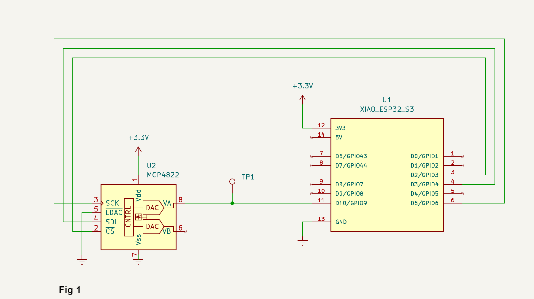
The first measurement circuit (Fig 1) is based on a Xiao ESP32S3 interfaced with an MCP4822 dual-channel 12-bit Digital-to-Analog Converter (DAC) via the SPI communication bus. The purpose of the circuit is to generate a programmable analog voltage that can be used as a reference, excitation signal, or control input within the measurement system.
Only Channel A of the MCP4822 is utilized in the current design. The analog output VA (Pin 8) is routed to:
- GPIO9 of the Raspberry ESP32S3
- Test point TP1 for measuring the voltage using the external DMM
This arrangement allows the ESP32S3 to generate a known analog voltage through the DAC and subsequently measure it using its internal Analog-to-Digital Converter (ADC).
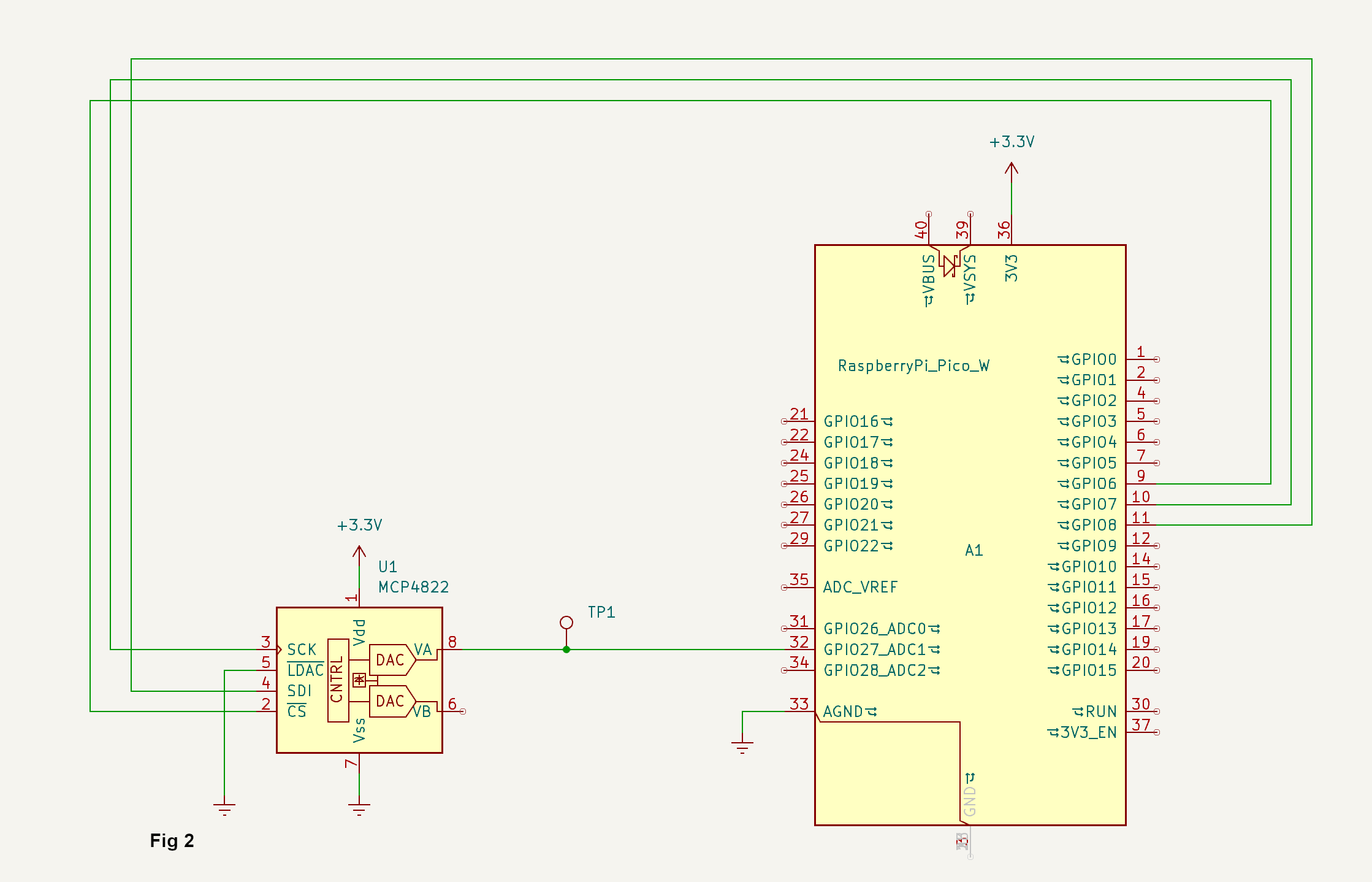
The measurement circuit for Raspberry Pico W/2W (Fig 2) is identical except for the microcontroller and pin assignments.
The Arduino Manager Widget List

To save time, we will use the attached Widget List. If you want to learn how to create it from scratch, you can read the other Instructables about Arduino Manager or consult its documentation.
To load the file in Arduino Manager procede with the following steps.
macOS
- Download the ADC Calibration.wl (I used an external shared file because Instructables does not allow files with unknown extensions to be uploaded)
- Open Arduino Manager
- From the side menu, select Widget Lists
- From the toolbar click Import and select the downloaded file
iPhone / iPad
- Download the ADC Calibration.wl (I used an external shared file because Instructables does not allow files with unknown extensions to be uploaded)
- Open Arduino Manager
- From the side menu, select Widget Lists
- From the toolbar click Import and select the downloaded file
Create the Connection to the board
Although no firmware is running on the board yet, we can create the two connections that will be used later.
- From side menu select Connections.
- New Connection (+)
- Enter the following values:
- Storage: Cloud
- Name: ADC - ESP 32
- IP: 192.168.1.150 (adapt to your network characteristics)
- Port: 8080
- Tap Save.
- New Connection (+) again.
- Enter the following values:
- Storage: Cloud
- Name: ADC - Pico
- IP: 192.168.1.151 (adapt to your network characteristics)
- Port: 8080
- Tap Save.
Select the Connection
Now we can select the connection in the Widget List. Since, we will start with the ESP32 board, we will select the connection to that board first.
- From the side menu select Widgets.
- Switch to Edit Mode.
- Click on the gear icon on the top right side of the screen.
- Set Connection to ADC - ESP 32.
- Switch back to Normal Mode.
The Widget List description
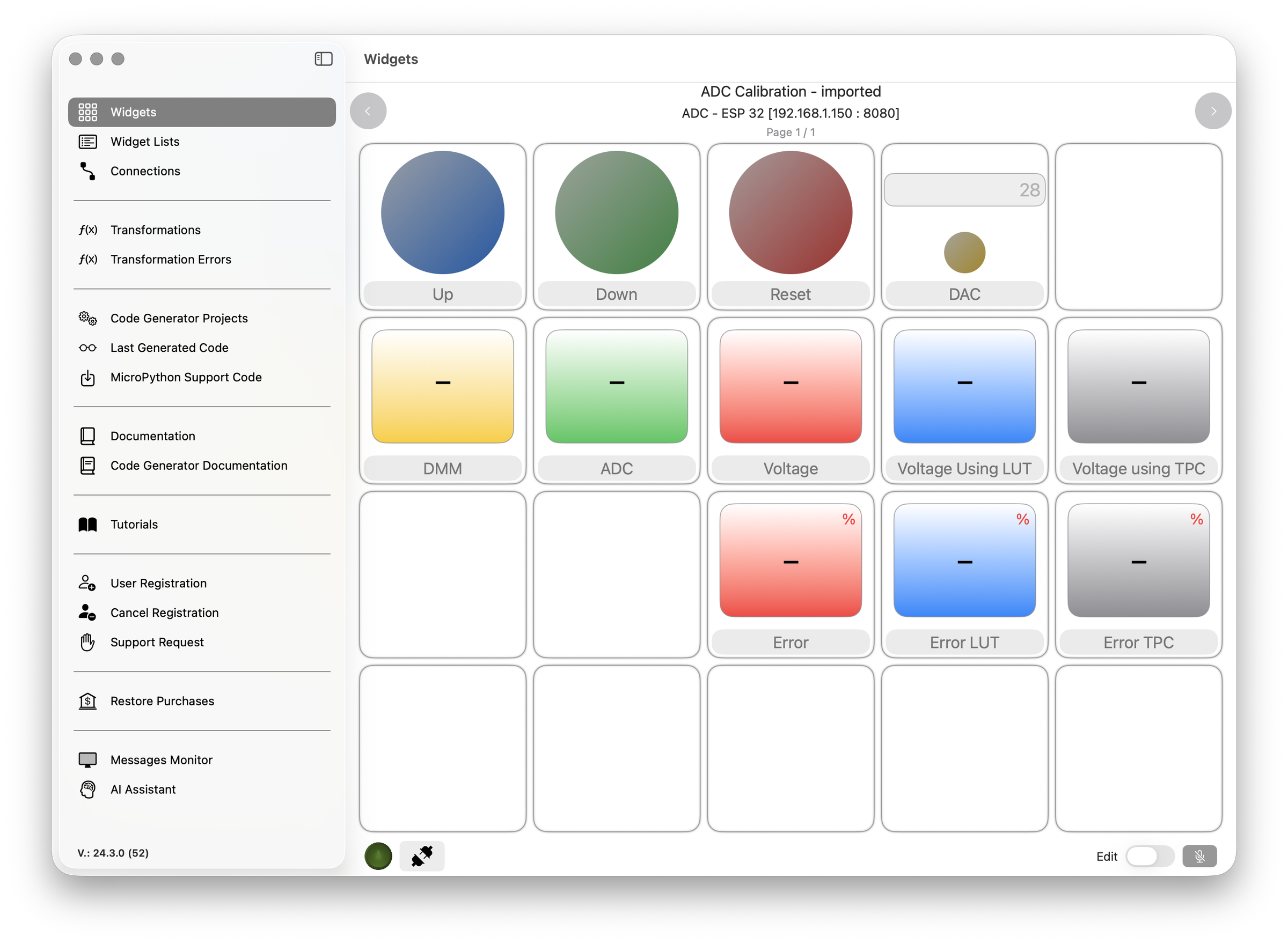
The widget list is composed of 5 Display Widgets that show the measured values:
- DMM: value measured by the DMM.
- ADC: raw value provided by the ADC.
- Voltage: voltage value calculated from the ADC reading.
- Voltage using LUT: corrected voltage value calculated using a Lookup Table (LUT).
- Voltage using TPC: corrected voltage value calculated using Two-Point Calibration (TPC).
Three additional Display Widgets show the error relative to the DMM measurement:
- Error %
- Error LUT %
- Error TPC %
Finally, there are three Push Button Widgets:
- Up: to increase the DAC output voltage.
- Down: to decrease the DAC output voltage.
- Reset: to reset the DAC output voltage to its initial value.
The DAC Input Field Widget can be used to set the DAC to a specific voltage directly.
Correct ESP32 ADC Readings
We will start with an ESP32 board and, with the help of Arduino Manager, analyze its ADC behavior without any correction, then compare it with readings corrected using Two-Point Calibration and a Lookup Table.
Arduino Manager provides both the Code Generator and the Pin Code Generator, which work together to generate code for the target board from the widgets included in the widget list.
This approach saves a considerable amount of programming time while minimizing the risk of errors.
Furthermore, when an ADC is involved, the generators significantly reduce the effort required to create a Lookup Table or calculate the parameters needed for Two-Point Calibration.
Let's get started.
- From the side menu select Code Generator Projects.
- Create a new project (+).
- Enter the following information:
- Name: ADC Calibration - ESP32
- Board: ESP32-WiFi
- Communication Device: Built in WiFi
- Language: C
- Connection: ADC - ESP32. Some fields are automatically filled.
- Netmask: 255.255.255.0 (adapt to your network characteristics)
- Gateway: 192.168.1.1 (adapt to your network characteristics)
- SSID: name of your network
- Password: password to your network
- Connection Callback: enabled
- Disconnection Callback: enabled
- Select Widget Pins tab.
- Select the Display Widget named ADC and enter the following information:
- Pin: 9 (according to the schematic)
- Ready Every: 700
- Averaging: enabled
- Number of Samples: 64
- Select the Display Widget named Voltage and enter the following information:
- Pin: 9 (according to the schematic)
- Ready Every: 700
- Averaging: enabled
- Number of Samples: 64
- Convert to voltage: enabled
- Vref: 3.3
- Click Generate.
- Click Save and Close.
Now the project is generated and ready to be uploaded to the board.
For now we have configured the Display that shows the raw ADC reading and the voltage reading converted using the basic formula well know formula:
V = ADCreading * Vref / (2^n - 1)
In the next steps we collect data for the Two-Points calibration and for the Lookup table.
Correct ESP32 ADC Readings - Reading Values From DMM
If your DMM supports SCPI protocol protocol over Ethernet, you can have its readings directly available in Arduino Manager. Otherwise, you will need to read them from the DMM display.
To read the DMM directly from the ESP32 board follow this steps:
- Locate the section
and add this code:
Adapt the ip address to the one used by your device.
- Locate the section
and add this code:
Without getting into details, DMM is accessed via TCP/IP and the reading is started issuing a specific command.
We are assuming that DMM used for the measurements is the Siglent SDM3055, you may need to adapt the code for different DMMs here:
- Locate the doWork section and add this code to periodically the voltage using the DMM
Correct ESP32 ADC Readings - Completing the Firmware
We need to add some additional code to control the ADC using the Push Button Widget
At the top of the code add the following lines:
and in the setup function add:
pushButtonUpCallback
pushButtonDownCallback
pushButtonResetCallback
Eventually, we have to handle the Input Field Widget in order to set the DAC at any desired value:
textFieldDACCallback
Open the code using the Arduino IDE, then upload it to your board.
Collecting Data for Two-Points Calibration
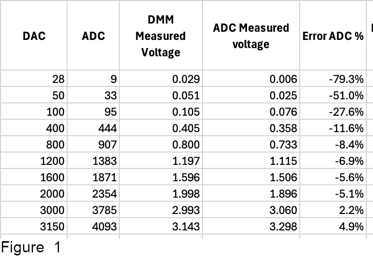
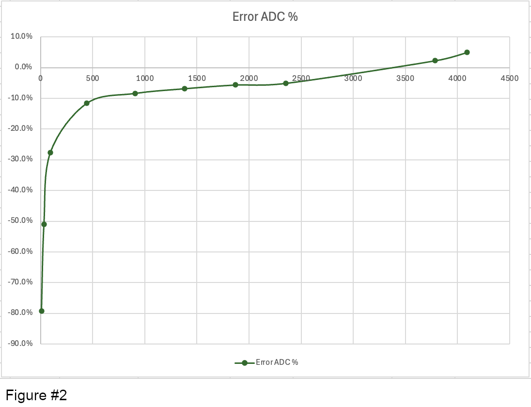
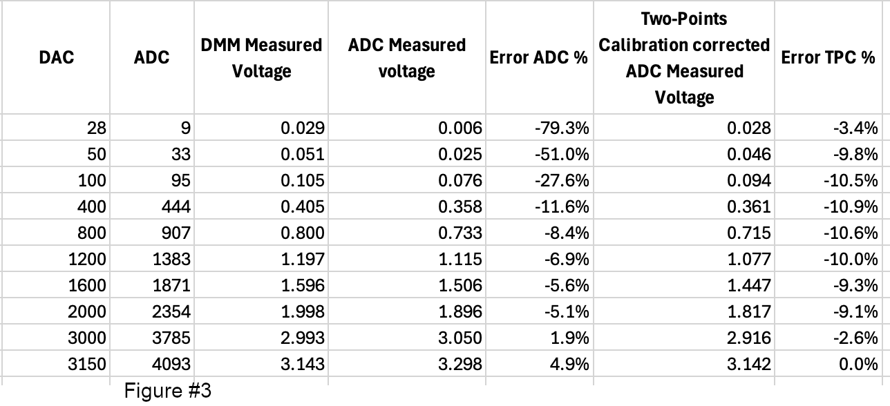
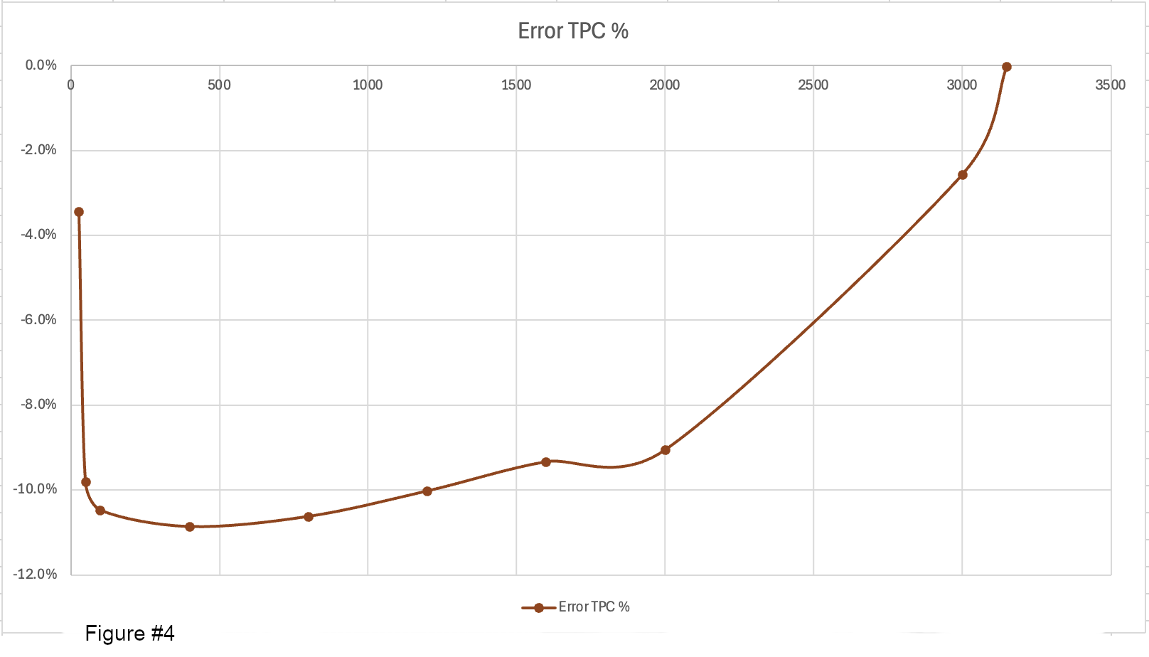
Eventually, we are ready to collect some useful data. For these purpose a template in Excel is available for download:
Using the Push Button Widgets and the Input Field Widget, we can set ADC values across the entire 0–3.3 V range according to the values listed in Table 1. For each value, enter both the DMM Measured Voltage and the ADC Measured Voltage as displayed in Arduino Manager.
We observe that the relative error is high across the entire measurement range, making the readings almost unusable (Figure #1 and Figure #2).
Please note: The values shown in this table and the following tables in this Instructable are specific to my setup, including the microcontroller, circuit, DAC, USB supply voltage, DMM, and other measurement conditions. Your readings will likely differ, but the overall behavior should be similar.
To correct the readings, we apply a two-point calibration using the first reading in the table, which is close to 0 V, and the last reading, which is close to the maximum input voltage accepted by the ADC.
- Select Code Generator Projects using the side menu.
- Select the project: ADC Calibration - ESP32 and edit it.
- Select the Widget Pins tab.
- Select the widget named: Voltage Using TPC and enter the following information:
- Pin: 9 (according to the schematic)
- Ready Every: 700
- Averaging: enabled
- Number of Samples: 64
- Convert to voltage: enabled
- Vref: empty
- Use Two-Points Calibration: enabled
- Min Measured: 9
- Min Expected: 0.029
- Max Measured: 4093
- Max Expected: 3.143
- Click Generate and then Save & Close.
- Upload the code to the board
After filling in the Two-Point Calibration Corrected ADC Measured Voltage column in Table 1, we can see that the error has changed shape but has not been reduced. On the contrary, in some cases, it is even worse (Figure #3 and Figure #4).
As mentioned earlier, two-point calibration provides better performance when the ADC is linear but exhibits offset and gain errors.
Collecting Data for the Lookup Table
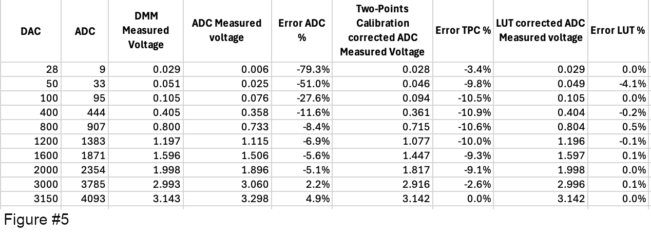
Unfortunately, this section is quite boring because a lot of value has to be collected. It worths the effort.
First we have to collect much more measurements points to have a reasonable precision. Using the buttons we collect the value to fill the Table 2 of the template.
Now we need all that values in a csv file for computing the Lookup table
- Copy the columns: ADC, DMM Measured Voltage in a new Excel sheet.
- File -> Save As ...
- Select the project folder, file format CSV UTF-8 and a file name (e.g. readings.csv)
Note: After saving, Excel switches to the CSV file. Close the CSV file and reopen the original Excel workbook to continue.
We can not get back to Arduino Manager:
- Select Code Generator Projects using the side menu.
- Select the project: ADC Calibration - ESP32 and edit it.
- Select the Widget Pins tab.
- Select the widget named: Voltage Using LUT and enter the following information:
- Pin: 9 (according to the schematic)
- Ready Every: 700
- Averaging: enabled
- Number of Samples: 64
- Convert to voltage: enabled
- Vref: empty
- Use Lookup Table: enabled
- Select and choose the previously saved CSV file
- Lookup Table Steps: 1 (the final lookup will not be compressed)
- Use Two-Points Calibration: disabled
- Click Generate and then Save & Close.
- Upload the code to the board
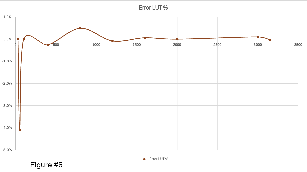
We can now fill the column LUT corrected ADC Measured voltage of Table 1 and we can see that the relative error is drastically reduced (Figure #5 and Figure #6).
Conclusion for ESP32
Due to the nonlinearity of the ESP32 DAC, using a lookup table is the most effective way to correct the ADC readings for this device.
Once the calibration data has been collected, the Arduino Manager Pin Code Generator automatically generates all the required code for you.
Correct Raspberry Pico ADC Readings - Preparing the Widget List
We now move on to the Raspberry Pi Pico ADC. We essentially need to repeat the work we did for the ESP32. To save time, we can copy the existing project and modify it.
- From the side menu open Code Generator Projects.
- Select ADC Calibration - ESP32.
- Duplicate it.
- Select ADC Calibration - ESP32 Copy and open it.
- Make the following changes:
- Name: ADC Calibration - Pico
- Board: Raspberry Pico 2 (or 2 W according to your availability)
- Language: C++ (native SDK)
- Connection: ADC-Pico (Ip and port are adapted according on the connection definition):
- Password: password to your network
- Connection Callback: enabled
- Disconnection Callback: enabled
- Select the Widget Pins tab
- Select the Widget named ADC and set the Pin to 27
- Select the Widget named Voltage and set the Pin to 27
- Select the Widget named Voltage using TPC and set the Pin to - (no data is available for the correction yet)
- Select the Widget named Voltage using Lookup Table and set the Pin to - (no data is available for the correction yet)
- Click Generate and then Save & Close.
- Open Visual Studio Code and import the project. If you are not familiar with setting up an Arduino Manager–generated Pico project in VS Code, refer to the Arduino Manager documentation under Raspberry Pi Pico W / 2 W Wi-Fi – C/C++ SDK.
- Don't forget to switch the connect to ADC - ESP Pico that we have already created.
Correct Raspberry Pico ADC Readings - Reading Values From DMM
To read the DMM directly from the Pico W/2W board follow this steps:
- Download the following files and copy them in your project folder. They provide some basic functions to connect and transfer data via tcp/ip
- tcp_client.h
- tcp_client.c
- Locate the section
and add this code:
- Locate the section
and add this code:
- Locate the section
and add this code:
- locate this section
and add this code;
- locate
and add this code:
Correct Raspberry Pico ADC Readings - Completing the Firmware
We need to add some additional code to control the ADC using the Push Button Widget
and add this code:
Collecting Data for Two-Points Calibration
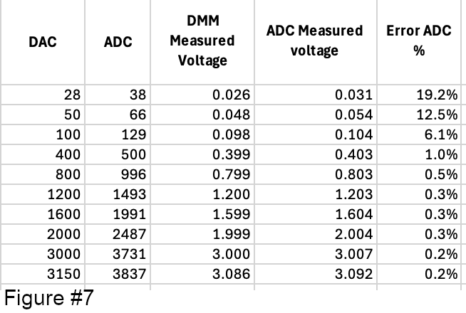
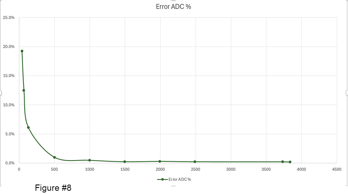

As we did for the ESP32 device, using the Push Button widgets and the Input Field widget, we can set a few discrete ADC values over the entire 0–3.3 V range, producing the values shown in Figure #7 and Figure #8.
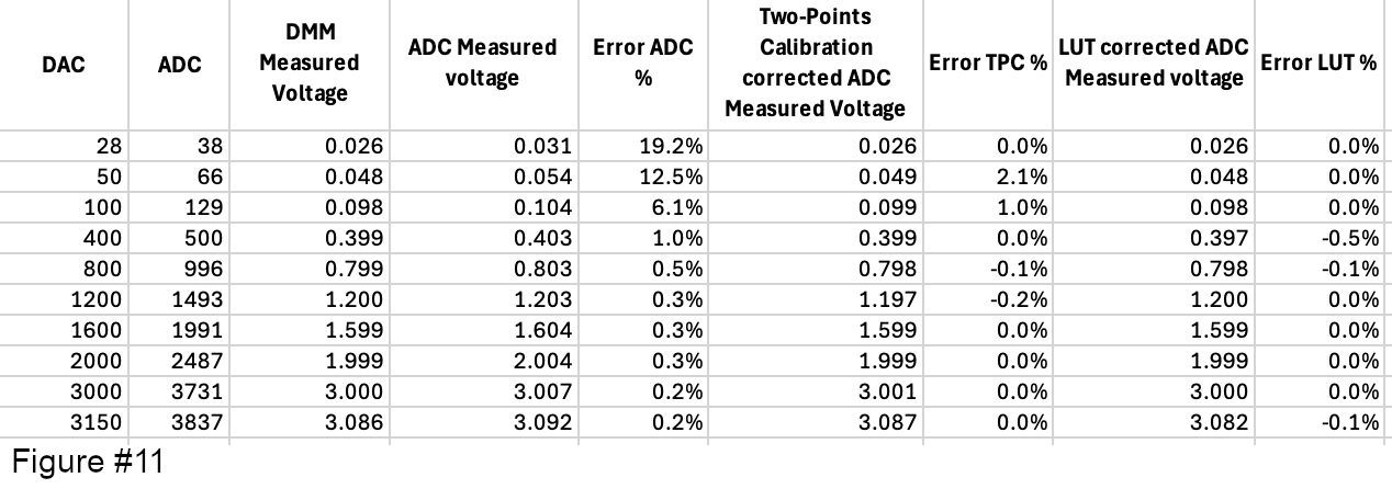
We see that the precision of the Pico’s ADC is generally better than the ESP32’s ADC precision. Nevertheless, we can try to improve the results by starting with a Two-Points Calibration using the first reading in the table (which is close to 0 V) and the last one (which is close to the maximum voltage accepted by the ADC).
- Select Code Generator Projects using the side menu.
- Select the project: ADC Calibration - Pico and edit it.
- Select the Widget Pins tab.
- Select the widget named: Voltage Using TPC and enter the following information:
- Pin: 9 (according to the schematic)
- Ready Every: 700
- Averaging: enabled
- Number of Samples: 64
- Convert to voltage: enabled
- Vref: empty
- Use Two-Points Calibration: enabled
- Min Measured: 38
- Min Expected: 0.031
- Max Measured: 3837
- Max Expected: 3.092
- Click Generate and then Save & Close.
- Compile and run the code to the board
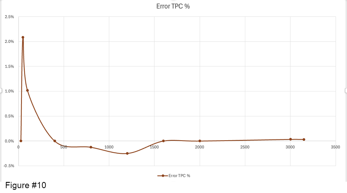
Filling the column Two-Points Calibration corrected ADC Measured Voltage of Table 1 we see that the error is reduced especially for low voltages taking advantage of the Pico's ADC linearity (Figure #9 and Figure #10)
Collecting Data for Lookup Table
Now we can try to get even better results using a LookUp Table.
First we have to collect much more measurements points to have a reasonable precision. Using the buttons we collect the value to fill the Table 2 of the template.
Now we need all that values in a csv file for computing the Lookup table
- Copy the columns: ADC, DMM Measured Voltage in a new Excel sheet.
- File -> Save As ...
- Select the project folder, file format CSV UTF-8 and a file name (e.g. readings.csv)
Note: After the save Excel switched to the CSV file. You need to close it and open the original Excel file again.
We can not get back to Arduino Manager:
- Select Code Generator Projects using the side menu.
- Select the project: ADC Calibration - Pico and edit it.
- Select the Widget Pins tab.
- Select the widget named: Voltage Using LUT and enter the following information:
- Pin: 27 (according to the schematic)
- Ready Every: 700
- Averaging: enabled
- Number of Samples: 64
- Convert to voltage: enabled
- Vref: empty
- Use Lookup Table: enabled
- Select and choose the previously saved CSV file
- Lookup Table Steps: 1 (the final lookup will not be compressed)
- Use Two-Points Calibration: disabled
- Click Generate and then Save & Close.
- Upload the code to the board
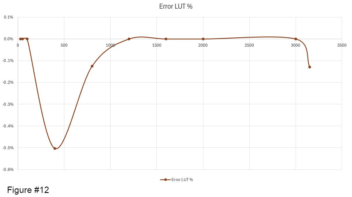
We can now populate the LUT Corrected ADC Measured Voltage column in Table 1. As shown, the relative error does not change significantly, but it is generally lower than that obtained with the Two-Point Calibration (Figure #11 and Figure #12).
Final Conclusions
Arduino Manager provides three main techniques to improve the accuracy of ADC readings:
- Averaging
- Two-point calibration
- Lookup table
These techniques, together with the code generators available in Arduino Manager, make it extremely quick and easy to improve ADC accuracy without writing code.
Two-point calibration requires very little effort, as it only involves measuring two points. However, it is effective only if the ADC has an approximately linear response, as is the case with the Raspberry Pi Pico's ADC. In contrast, a lookup table can significantly improve accuracy, especially when the ADC response is non-linear, as with the ESP32's ADC. The trade-off is that it requires considerably more effort because a much larger number of measurements must be taken.
Whichever correction technique you choose, Arduino Manager can handle the complexity for you:
- No correction: Arduino Manager uses the amController's to_voltage() function to automatically convert ADC integer readings into voltage.
- Two-point calibration: Arduino Manager uses the amController's linearization functions and automatically calculates the calibration coefficients to minimize offset and gain errors.
- Lookup table: Arduino Manager uses the DMM readings you provide to automatically generate a lookup table that compensates for the ADC's non-linearity, resulting in a more accurate voltage measurement.