How to Control an RGB LED With Arduino Uno
by rachnaj in Circuits > Arduino
29 Views, 0 Favorites, 0 Comments
How to Control an RGB LED With Arduino Uno
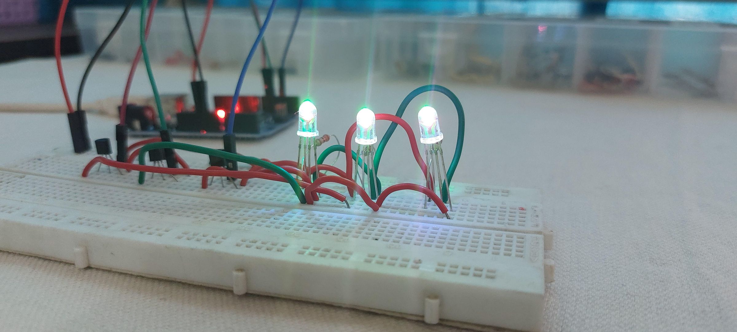
RGB LEDs are a simple way to add colourful visual effects to an Arduino project. Unlike a standard LED that produces a single colour, an RGB LED contains red, green, and blue LED elements inside one package. By controlling the brightness of these three elements, you can create many different colours.
In this project, I’ll show you how to connect a common-cathode RGB LED to an Arduino Uno, control the individual red, green, and blue channels, and combine colours using PWM. I’ll also cover how multiple RGB LEDs can be used to create a simple LED light show.
Related Arduino guide: For more beginner-friendly Arduino electronics projects, you can also explore the Arduino projects and tutorials on Play With Circuit.
What You’ll Learn
- How an RGB LED works
- The difference between common-anode and common-cathode RGB LEDs
- How to identify the common terminal of an RGB LED
- How to connect an RGB LED to an Arduino Uno
- How PWM controls LED brightness
- How different RGB values create different colours
- How multiple RGB LEDs can be used for lighting effects
Supplies
Arduino Uno R3
1 x Common-cathode RGB LED
3 x 220 Ω resistors
Breadboard
Jumper wires
USB Type-A to Type-B cable
Understanding an RGB LED
An RGB LED contains three separate LED elements:
- R – Red
- G – Green
- B – Blue
Each colour can be controlled independently. When two or more colours are illuminated together, they combine to produce another colour.
For example:
- Red + Green = Yellow
- Red + Blue = Magenta
- Green + Blue = Cyan
- Red + Green + Blue = White
The final colour depends on the brightness of each individual LED. This makes RGB LEDs useful for decorative lighting, indicators, displays, Arduino projects, and interactive electronics.
Know Your RGB LED Pins
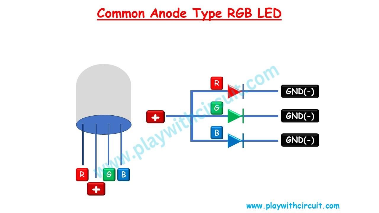
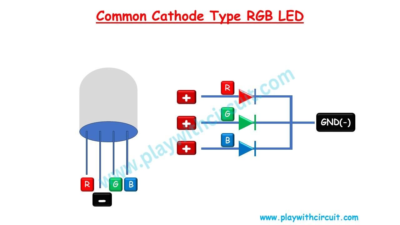
A typical 4-pin RGB LED has four terminals. Three terminals control the individual colours, while the fourth is the common connection.
Depending on the LED, the common terminal can be either:
- Common Anode (+)
- Common Cathode (−)
Common-Anode RGB LED
In a common-anode RGB LED, the positive terminals of the red, green, and blue LED elements are internally connected.
The common pin is connected to the positive supply, while the individual colour pins are connected to the control circuit.
To turn a particular colour on, its corresponding pin is driven LOW.
Common-Cathode RGB LED
In a common-cathode RGB LED, the negative terminals of the three LED elements are internally connected.
The common cathode is connected to GND, while the red, green, and blue pins are controlled individually.
A HIGH signal on a colour pin turns that colour on.
For this project, we’ll use a common-cathode RGB LED.
Important: Always use an appropriate current-limiting resistor with the LED. Connecting an LED directly to a power source or Arduino output can damage the LED or the Arduino pin.
Wire the RGB LED to Arduino Uno
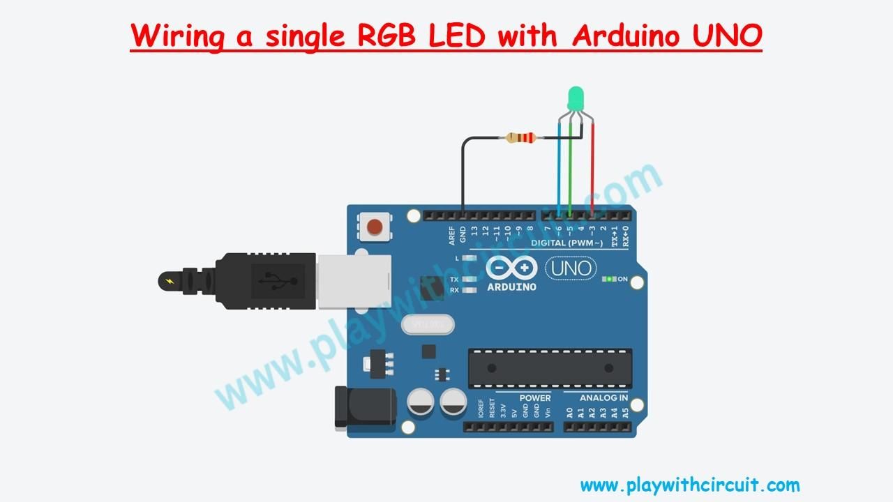
For this example, use Arduino's PWM-capable pins:
- Red → Arduino pin 3
- Green → Arduino pin 5
- Blue → Arduino pin 6
- Common cathode → GND
Place a suitable resistor in series with each RGB channel.
These pins are useful because Arduino Uno supports PWM on pins 3, 5, and 6. PWM allows us to control the apparent brightness of each colour instead of simply switching it ON or OFF.
Make an RGB LED Light Show
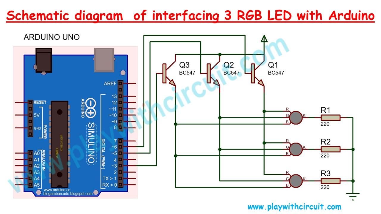
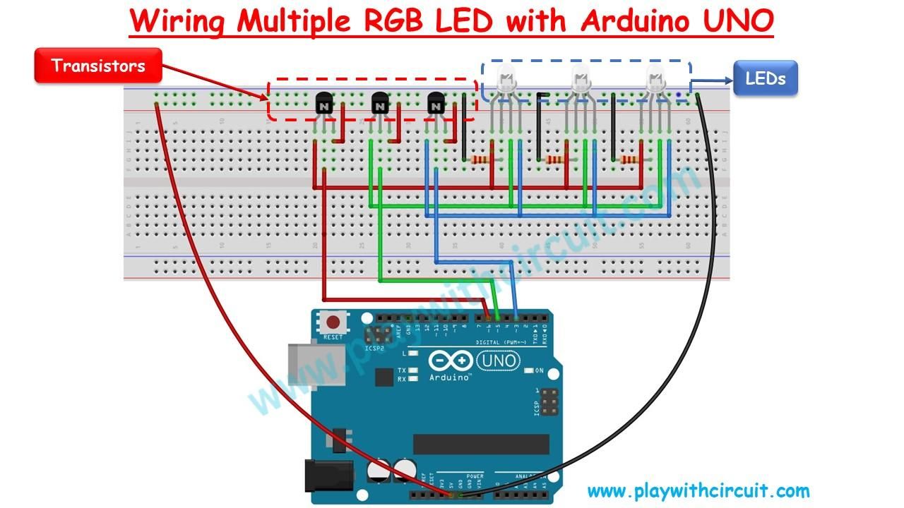
Once you have one RGB LED working, you can take the project a step further and create a small LED show using multiple RGB LEDs.
The basic idea is to control the brightness of the red, green, and blue channels independently and continuously change their PWM values.
For example, you can create effects such as:
- Red → Green → Blue
- Red → Yellow → Green
- Blue → Magenta → Red
- Gradual colour fading
- Random colour patterns
- Alternating LED sections
PWM is particularly useful here because it allows smooth changes instead of simply turning LEDs ON and OFF.
Final Result
That's it! You now have a basic Arduino Uno RGB LED controller that can generate individual colours as well as mixed colours.
The really fun part is experimenting with PWM values. Once the basic circuit works, you can turn it into a colour-changing lamp, mood light, status indicator, decorative display, or a more advanced multi-LED lighting system.
If you want to take the project further, try adding a potentiometer, push buttons, a light sensor, or a Bluetooth module and use them to control the RGB colours dynamically.