How to Convert 2 or 2.5 Channel IR RC Helicopter Toy Into 3 Channel (ATtiny85 Dead-Bug Mod).
by _Mr_I_C_ in Circuits > Electronics
221 Views, 1 Favorites, 0 Comments
How to Convert 2 or 2.5 Channel IR RC Helicopter Toy Into 3 Channel (ATtiny85 Dead-Bug Mod).

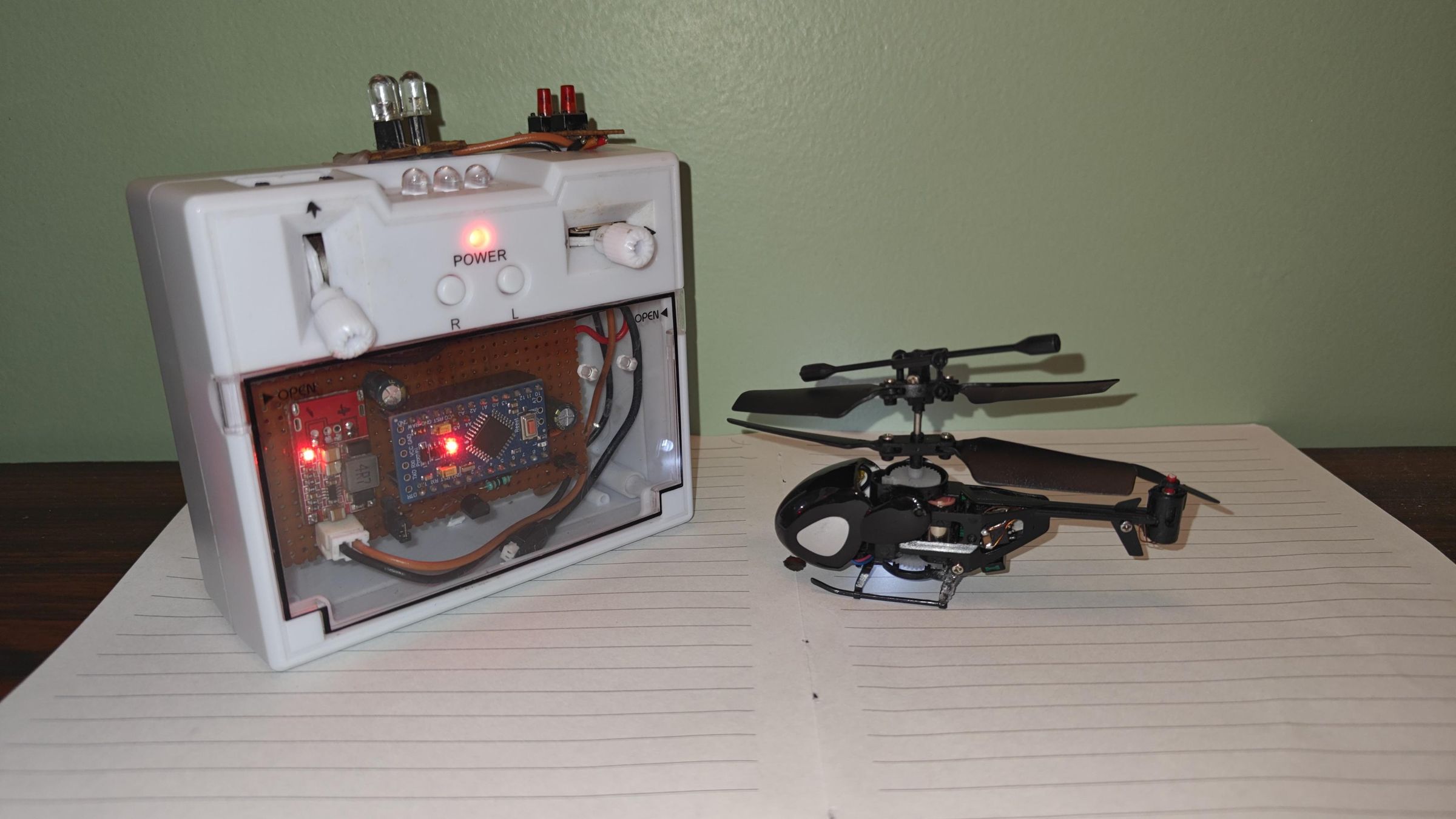
Cheap 2.5-channel infrared RC helicopters (like the famous QS5012) are notoriously difficult to control because they lack active tail-rotor pitch control. They constantly drift forward while spinning endlessly in circles. This step-by-step guide demonstrates how to overcome these limitations by micro-soldering an ultra-lightweight (0.1 g) custom ESC on an ATtiny85 microcontroller and modifying the stock transmitter.
Supplies
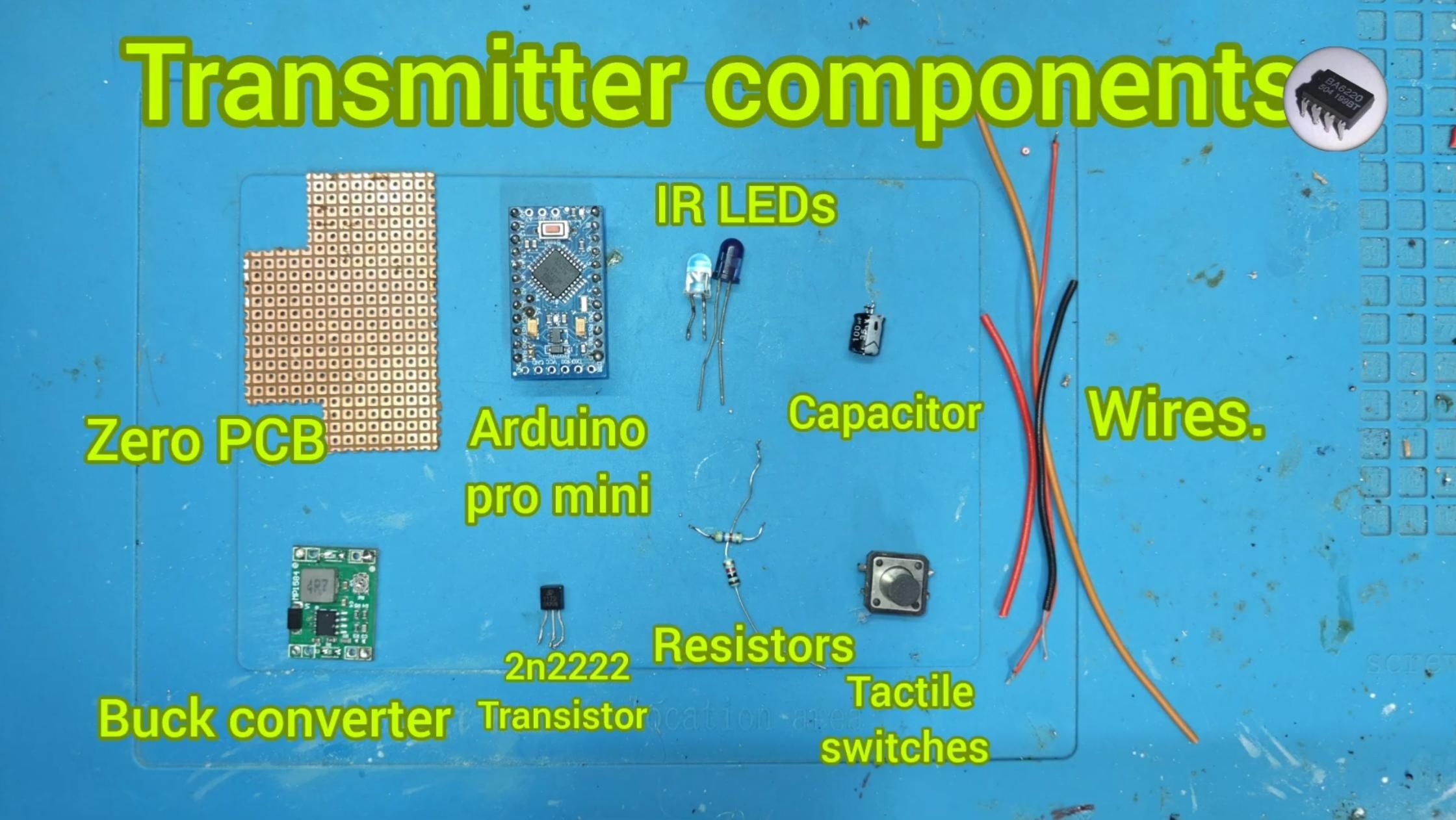
Transmitter Modification:
1x Stock IR Remote Controller
1x Arduino Pro Mini
1x Buck Converter (5V output)
1x 2N2222 NPN Transistor
1x 40*30mm Zero PCB(Perf board)
2x Tactile Push Buttons
3x 5mm IR LEDs (taken from an old remote)
2x Resistors (5 ohms and 220 ohms for series transistor drive)
2x Capacitors (100uf 35v)
2S Li-Po Battery Pack (custom fitted inside the enclosure)
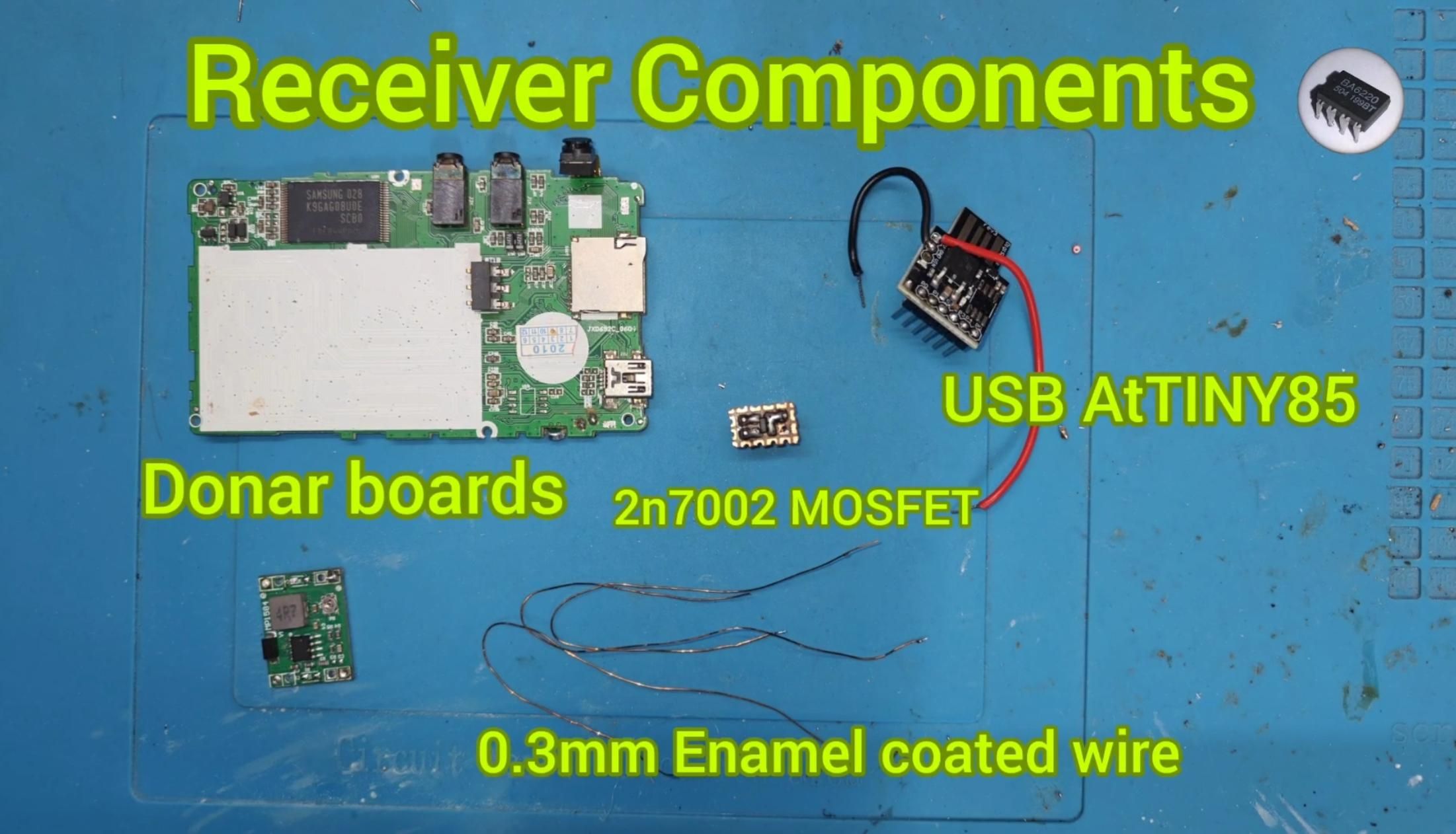
Helicopter Receiver Board:
1x USB ATtiny85
1x N-Channel SMD MOSFET(2N 7002)
Donar boards(for getting SMD caps and diode)
2x Resistors (220ohm and 10K SMD 0805)
Enamelled Copper Magnet Wire
Modify the Transmitter Hardware
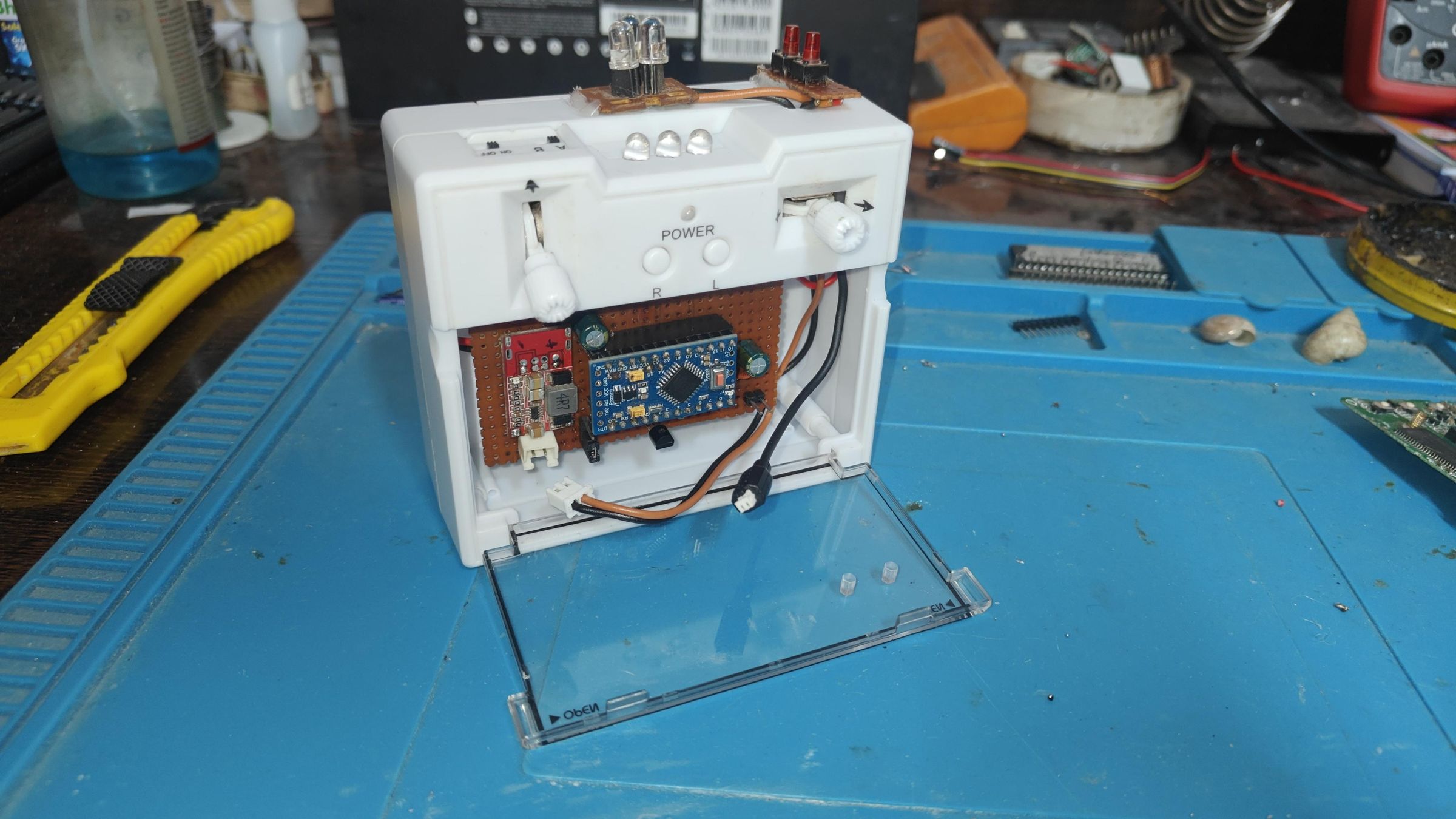
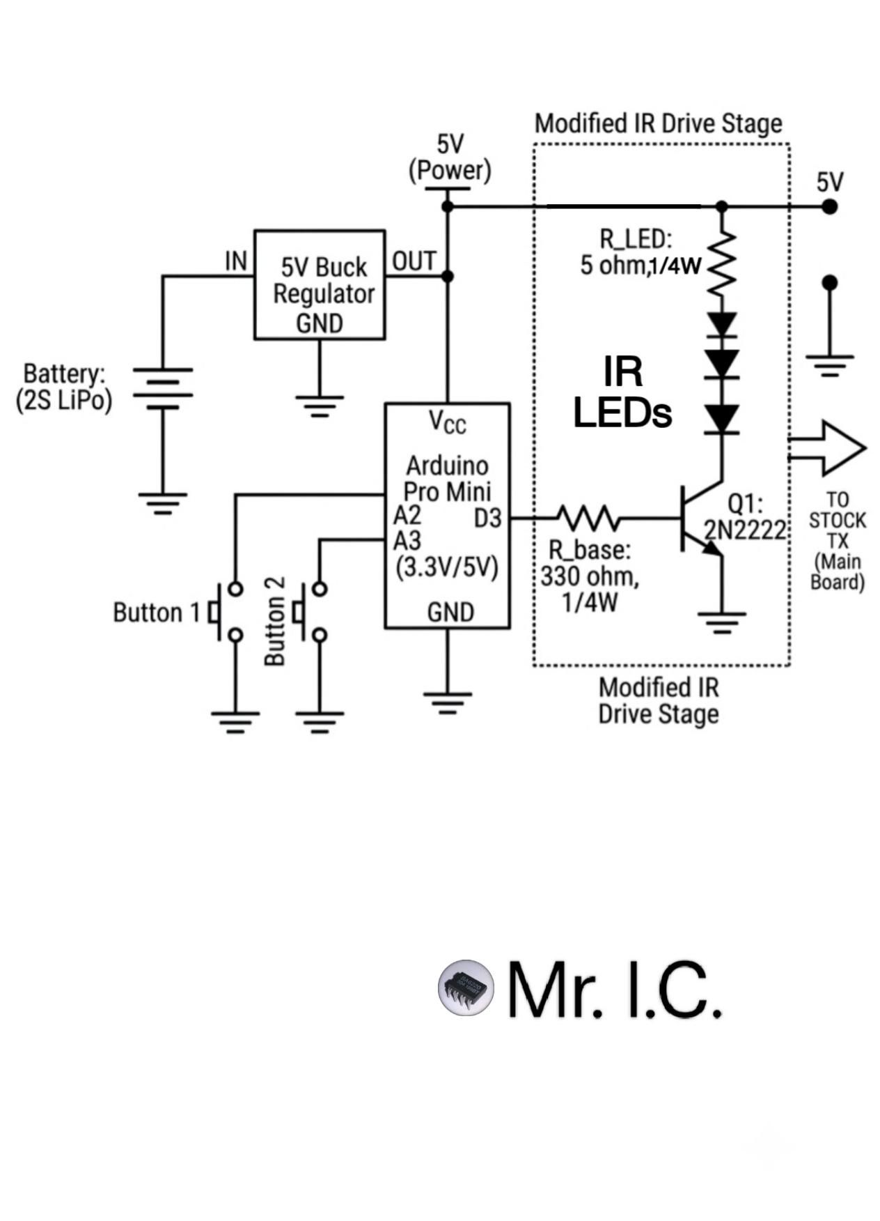
1. Power Supply & Enclosure: Open the stock remote enclosure and fit a custom 2S battery pack. Wire the battery output into a 5V buck converter to power the Arduino Pro Mini cleanly.
2. Drive Circuitry: Wire the Arduino Pro Mini's digital outputs(D3) to a 2N2222 transistor via current-limiting resistors(330ohm). Connect three 5mm IR LEDs in series via 5 ohm series resistor to boost the infrared signal transmission range. See the circuit diagram.
3. Controls: Mount two additional tactile push switches onto the transmitter body. Connect these switches to the Arduino inputs (A2 and A3) to control tail motor.
4. Firmware: Program the Arduino Pro Mini (with the provided .ino file) to transmit encoded IR commands matching the timing expected by the custom receiver.
Downloads
Build the ATtiny85 "Dead-Bug" Micro-ESC
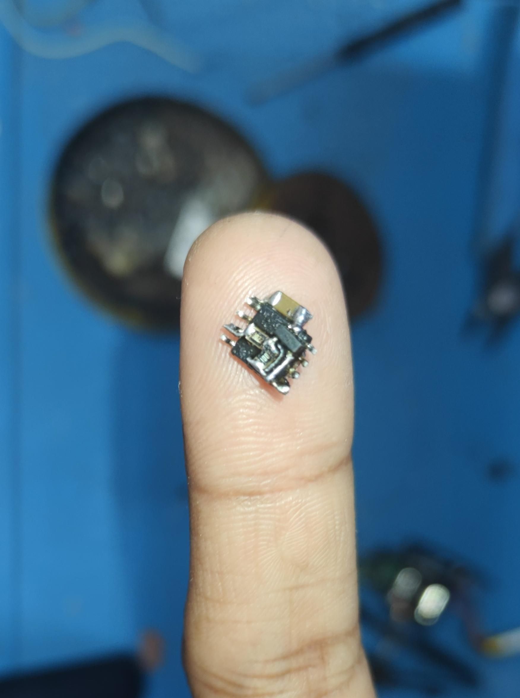
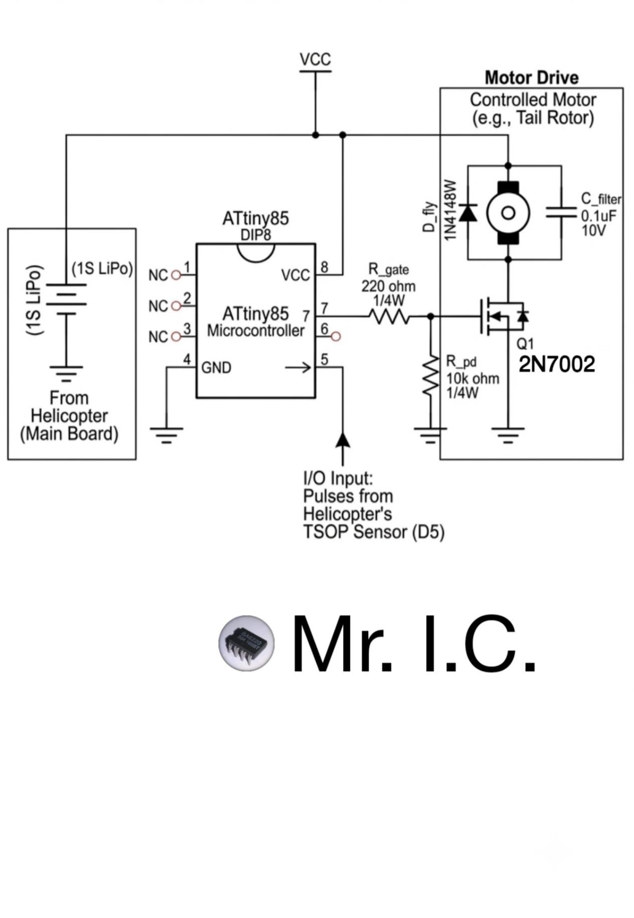
To avoid ruining the helicopter's center of gravity (CG), traditional PCBs cannot be used.
1. Flip the pre-programmed (with the provided .ino file) ATtiny85 SOIC-8 chip upside down ("dead-bug style").
2. Solder an N-Channel 2N7002 SMD MOSFET to the chip's Pin 2 (PB3) via 220ohm resistor, to act as the tail-motor driver.
3. Wire the output of the TSOP IR sensor to Pin 5 (PB0) of the ATtiny85.
4. Connect the main power rails (VCC Pin 8 and Ground Pin 4) from the helicopter's internal LiPo battery source.
Downloads
Install & Wire the Helicopter Receiver
1. Integration: Remove the helicopter canopy and mount the dead-bug circuit inside the main fuselage frame.
2. Motor Connections: Solder the tail-rotor motor wires across the MOSFET output pins.
3. Bench Test: Power on both the transmitter and the receiver. Press the control buttons on the remote to ensure the tail rotor spins correctly. If the motor blows air upward instead of downward (or vice versa), swap the motor positive and negative leads.
Final Testing & Flight Tuning
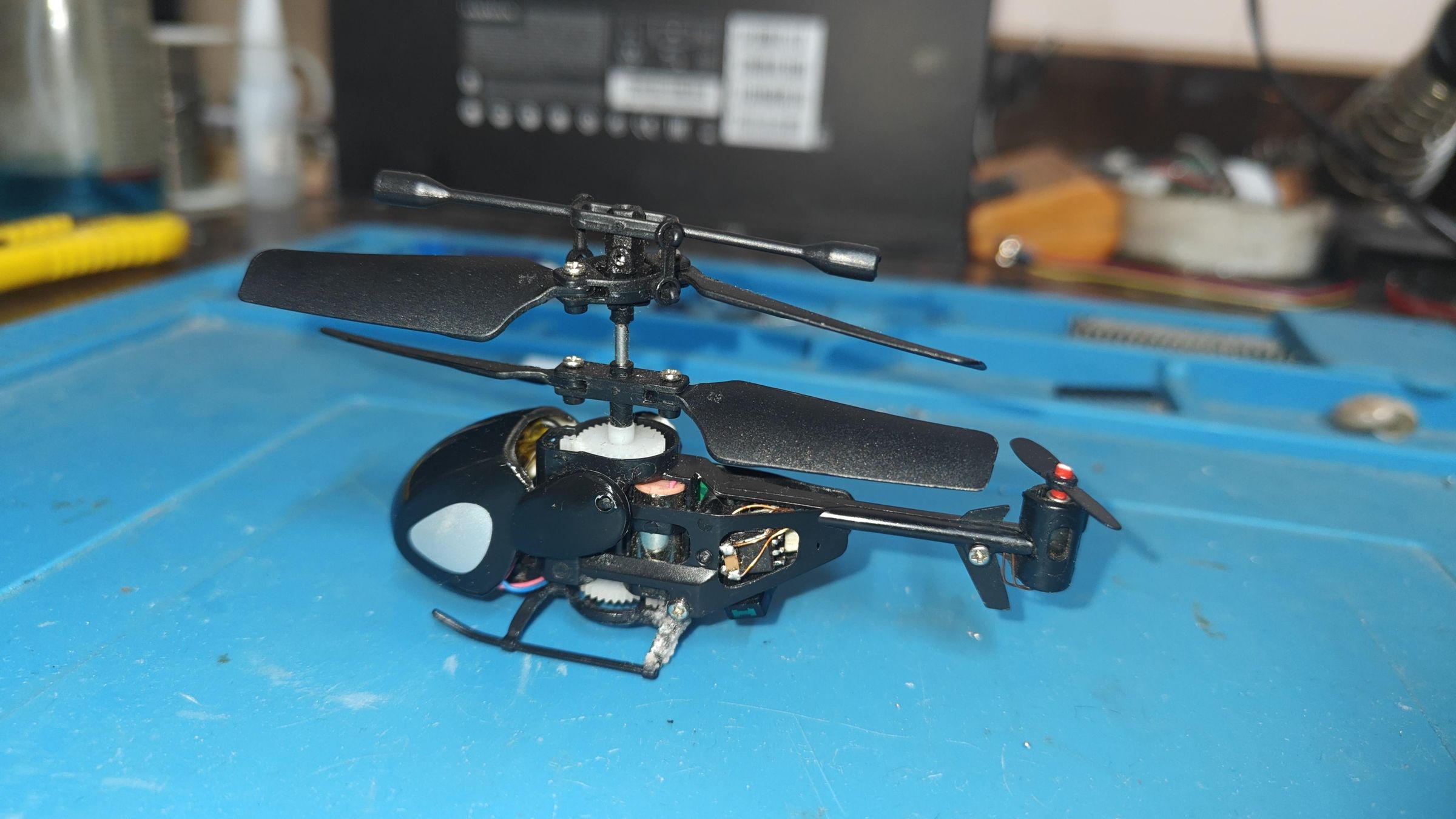
- Snap the canopy back onto the fuselage, ensuring no magnet wires rub against the main gear mesh.
- Place the helicopter on a flat surface and spin up the main throttle.
- Use the new tail-control buttons to active-trim the rotation, allowing full forward movement, precise hovering, and steady maneuvers.
- For more details and flying test, watch my YouTube video.