How to Drive a Led With Arduino or Potentiometer (CN5711)
by dariocose in Circuits > LEDs
6070 Views, 15 Favorites, 0 Comments
How to Drive a Led With Arduino or Potentiometer (CN5711)


I like LEDs, especially for personal projects, like making torches and lights for my bike.
In this tutorial I will explain the operation of a simple ic to drive leds that meets my needs:
- Vin < 5V to use a single lithium battery or USB
- possibility to vary the current with a potentiometer or with a microcontroller
- simple circuit, few components and small footprint
I hope this little guide will be useful to other users!
UPDATE [28/11/2023]
After writing this guide I created a board based on the CN5711 compatible with Arduino. Check it out >> https://youtu.be/NEFgN7a4vQM
Supplies


Components
- Led driver module
- Any power led (I used 1 watt red led with 60° lens)
- Battery or power supply
- Breadboard
For the diy version:
Tools
- Soldering iron
- Screwdriver
Datasheet


A few months ago I found on Aliexpress a led driver module composed of a CN5711 IC, a resistor and a variable resistor.
From the CN5711 datasheet:
General Description: The CN5711 is a current regulation integrated circuit operating from an input voltage of 2.8V to 6V, the constant output current can be set up to 1.5A with an external resistor. The CN5711 is ideal for driving LEDs. [...] The CN5711 adopts the temperature regulation instead of temperature protection function, the temperature regulation can make the LED being turned on continuously in case of high ambient temperature or high voltage drop.[...]
Applications: Flashlight, High-brightness LED driver, LED headlights, Emergency lights and lighting [...]
Features: Operating Voltage Range: 2.8V to 6V, On-chip Power MOSFET, Low Dropout Voltage: 0.37V @ 1.5A, LED Current up to 1.5A, Output Current Accuracy: ± 5%, Chip Temperature Regulation, Over LED Current Protection [...]
There are 3 modes of operation for this IC:
- With a PWM signal directly applied to the CE pin, the frequency of the PWM signal should be less than 2KHz
- With a logic signal applied to the gate of an NMOS (Figure 4)
- With a potentiometer (Figure 5)
Using the PWM signal it is very easy to drive the IC with a microcontroller like Arduino, Esp32 and AtTiny85.
Downloads
Drive the Led With the Built in Potentiometer


I hope the wiring is clear in the photos and video.
V1  >> blue  >> power supply +
CE  >> blue  >> power supply +
G   >> gray  >> ground
LED >> brown >> led +
To power the circuit I used a cheap power supply (made with an old atx power supply and a ZK-4KX buck boost converter). I set the voltage to 4.2v to simulate a single cell lithium battery.
As we can see from the video, the circuit powers from 30mA to more than 200mA
Drive the Led With a Microcontroller


To control the circuit with a microcontroller just connect the CE pin to the PWM pin of the microcontroller.
V1  >> blue   >> power supply +
CE  >> purple >> pwm pin
G   >> gray   >> ground
LED >> brown  >> led +
Setting the duty cycle to 0 (0%) the LED will turn off. Setting the duty cycle to 255 (100%) the LED will light up at maximum power. With a few lines of code we can adjust the brightness of the LED.
In this section you can download a test code for Arduino, Esp32 and AtTiny85.
Arduino test code:
#define pinLed 3

#define ledOff 0
#define ledOn 250 //255 is the maximum pwm value

int value = 0; //pwm value

void setup() {
 pinMode(pinLed, OUTPUT); //setto il pin pwm come uscita
}

void loop() {
 //blink
 analogWrite(pinLed, ledOff); // Turn off led
 delay(1000);         // Wait a second
 analogWrite(pinLed, ledOn);  // Turn on led
 delay(1000);         // Wait a second
 analogWrite(pinLed, ledOff); //...
 delay(1000);
 analogWrite(pinLed, ledOn);
 delay(1000);

 //dimm
 for (value = ledOn; value > ledOff; value --) { //decrease the light by decreasing "value"
  analogWrite(pinLed, value);
  delay(20);
 }

 for (value = ledOff; value < ledOn; value ++) { //increase the light by increasing "value"
  analogWrite(pinLed, value);
  delay(20);
 }
}
Edited: I uploaded the code on github https://github.com/dariocose/CN5711Arduino
Diy Version


I made a diy version of the module following the standard datasheet circuit.
I used a 50k potentiometer even though the datasheet says the "R-ISET's maximum value is 30K ohm".
As you can see the circuit is not very clean...
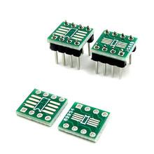
I should have used SOP8 to DIP8 pcb or SOP8 to DIP8 adapter for a more elegant circuit!
I hope to share a gerber file soon that you can use.
See You Soon!
Please leave me your impressions with a comment and report technical and grammatical errors!
Support me and my projects at this link https://allmylinks.com/dariocose