How to Estimate Pressure Drop in Small-Bore Tubing Before Choosing a Pump
by AlexHu in Circuits > Sensors
7 Views, 0 Favorites, 0 Comments
How to Estimate Pressure Drop in Small-Bore Tubing Before Choosing a Pump
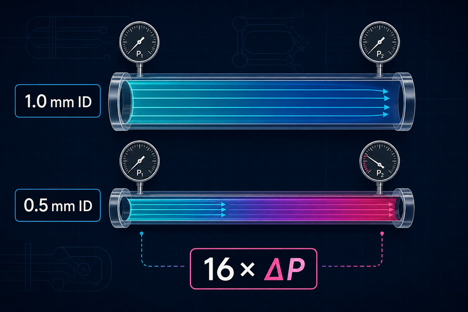
Small-bore tubing can consume much more pressure than expected. For fully developed laminar flow in a circular tube, pressure drop is approximately proportional to length and flow rate, but inversely proportional to the fourth power of the tube inner diameter.
That fourth-power relationship is the reason a seemingly small tubing change can completely alter a fluid system. If the inner diameter changes from 1.0 mm to 0.5 mm while the fluid, length, and flow rate remain the same, the idealized tube pressure drop becomes about 16 times larger.
This tutorial shows a repeatable early-design workflow for estimating that effect, checking assumptions, and comparing the result with a pump operating point. It is useful for microfluidic prototypes, laboratory automation, IVD fluid paths, dosing systems, and other low-flow instruments.
The result is an engineering estimate, not a substitute for supplier data, material compatibility work, safety analysis, or representative bench testing.
Supplies
Target flow rate or available pressure
Fluid type and operating temperature
Tubing inner diameter and installed length
A list of valves, fittings, filters, needles, manifolds, bends, and other restrictions
Supplier pump curve or representative bench-test data
A web browser and spreadsheet or engineering calculator
Define the Operating Condition
Start with one clearly defined operating point. Record:
• Fluid and temperature
• Target flow rate, or available pressure drop
• Tube inner diameter, not only the outside diameter
• Effective installed length
• Any known component flow coefficients or local-loss coefficients
Use the actual operating temperature because viscosity can change significantly with temperature. Also check the tubing drawing and tolerance: in a small-bore path, inner-diameter variation can dominate the calculated result.
Check Whether a Laminar-Tube Estimate Is Reasonable
For a straight circular tube with laminar flow, the Hagen–Poiseuille relationship gives:
ΔP = 128 μ L Q / (π d⁴)
where ΔP is pressure drop, μ is dynamic viscosity, L is tube length, Q is volumetric flow rate, and d is tube inner diameter.
Before relying on this relationship, check that the flow is laminar and that the tube can be treated as circular and reasonably straight. Entrance effects, pulsation, tubing deformation, gas bubbles, roughness, partial blockage, and non-Newtonian fluids can make the real result different.
Calculate a Base Case
Consider water near room temperature flowing through 500 mm of straight tubing at 10 mL/min.
For a 1.0 mm inner diameter, the idealized laminar-tube pressure drop is approximately 3.4 kPa. The corresponding Reynolds number is approximately 210, so a laminar estimate is reasonable for this simplified case.
You can reproduce the calculation in a spreadsheet, or use the free FOREACH Fluid Resistance and Pressure Drop Calculator to build a multi-element path and review the assumptions:
https://www.foreachtek.com/en/resources/calculators/fluid-resistance/
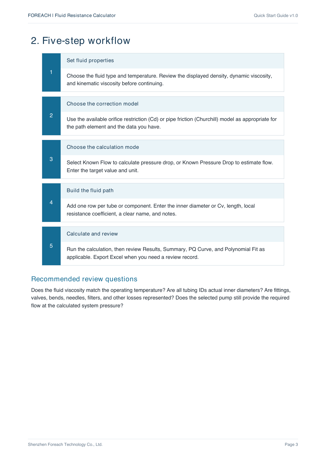
Select the fluid and temperature, choose the calculation mode, enter the flow rate, and add one row for the tube segment. Always check the displayed units before calculating.
Run an Inner-Diameter Sensitivity Check
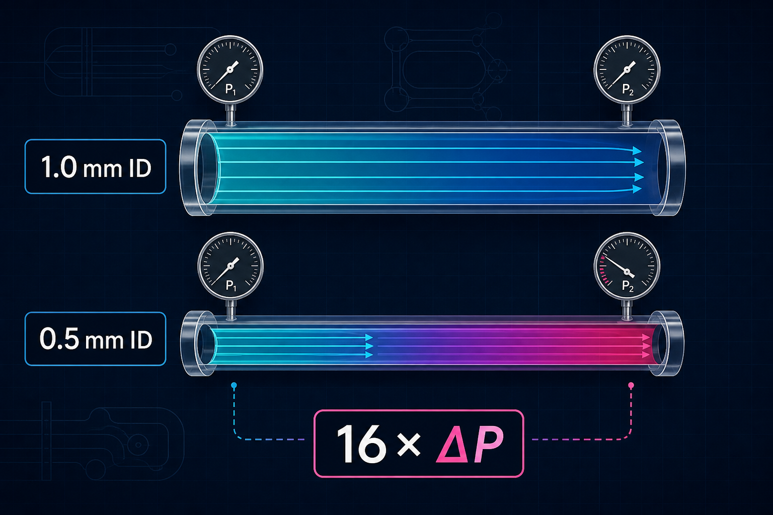
Now change only the tube inner diameter from 1.0 mm to 0.5 mm.
Because pressure drop varies approximately with 1/d⁴ in this laminar circular-tube model:
(1.0 / 0.5)⁴ = 16
The estimated straight-tube pressure drop rises from about 3.4 kPa to about 54 kPa. The Reynolds number remains in the laminar range for this simplified example, but the pressure requirement changes dramatically.
This sensitivity check is valuable before choosing a pump. A pump that looks adequate for the nominal tube size may miss the required flow when the actual tubing ID, tolerance, or aging behavior is considered.
Add the Losses That the Straight-Tube Equation Misses
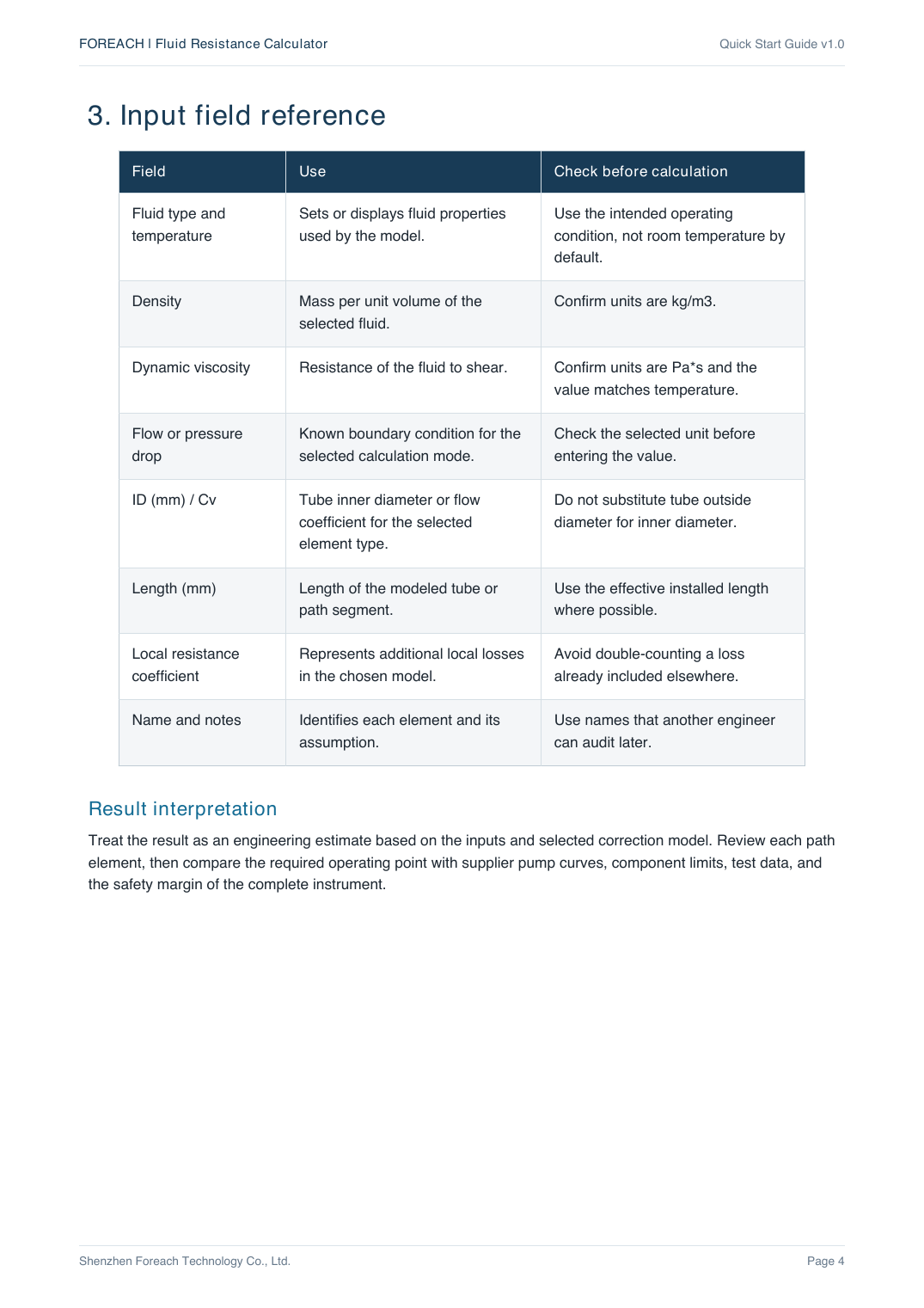
A real fluid path is rarely just one straight tube. Review every element between the inlet and outlet:
• Valves and check valves
• Fittings, tees, elbows, and reducers
• Needles, nozzles, and sampling probes
• Filters and membranes
• Manifolds and narrow passages
• Entrances, exits, and sudden area changes
• Pinched or deformed flexible tubing
Use measured data, supplier curves, Cv values, or appropriate local-loss coefficients when available. Avoid double-counting a loss that is already included in a component model.
Compare the System Requirement With the Pump Curve
The required operating point is the intersection of the system pressure requirement and the pump performance curve. Do not choose a pump using only its free-flow rating or maximum-pressure rating.
Review these questions:
• Does the pump still provide the target flow at the calculated system pressure?
• Is there enough margin for tubing tolerance, contamination, temperature, and aging?
• Will pulsation or tubing elasticity affect the instrument?
• Are wetted materials compatible with the fluid?
• Has the complete path been tested under representative conditions?
Treat the estimate as a design-screening tool. Validate the final assembly with supplier data and representative bench testing before release.
The most useful early-design habit is not searching for a single “correct” pressure-drop number. It is running sensitivity cases and documenting which assumptions change the pump operating point.
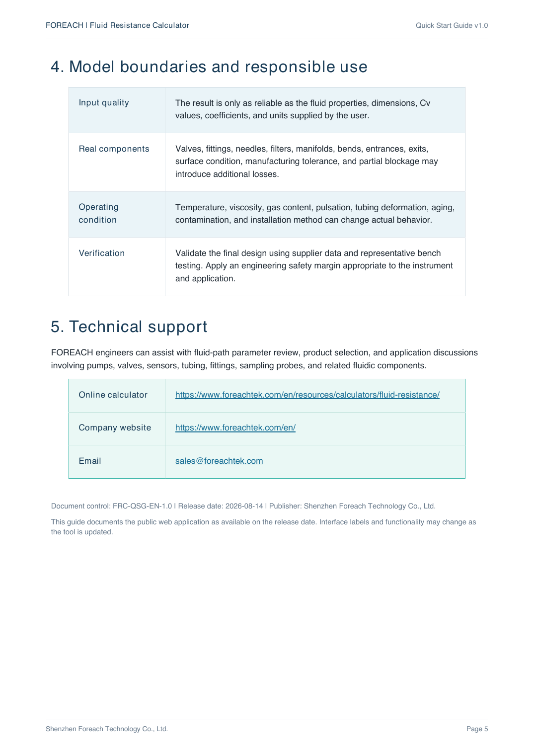
Disclosure: this tutorial was prepared by the FOREACH engineering team, which develops miniature pumps, valves, and fluid-path components. The linked calculator is provided as a free early-stage engineering aid. Questions about pumps, valves, sensors, tubing, fittings, and IVD or laboratory fluid paths can be sent to sales@foreachtek.com.