How to Make Radar System Using Arduino
by ROBO HUB in Circuits > Arduino
10306 Views, 83 Favorites, 0 Comments
How to Make Radar System Using Arduino


Hello everyone, In this instructables i will show you how i made this small yet functional radar system using arduino that has a mini display and shows the object scanned nearby in real time.
To begin with let me tell you what is this project all about and what made me to build this project.
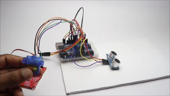
This is an ultrasonic sensor or HC-SR04 module power radar system and here the ultrasonic sensor detects the obstacle around it and the servo is used to scan the surroundings.
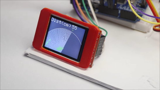
Upon scanning if any object is detected by the sensor than the display shows it as green dots in the LCD display and all this happens in real time thus to show that it is similar to the actual model.
To run all this components we are using arduino uno and like always i have given the program in the following instructables.
There is no rule that you have to use the exact same setup like i did, but i chose few 3d printed parts so that the model looks cool.
To power this project i will use a power bank and is connected to the uno board using the cable.
If you are a builder and want to try something cooler this is the perfect idea since you will get a chance to have hands on experience in the electronics part as well as the hardware part.
Building such real world projects is fun and enables to come up with more and more interesting ideas.
If you feel you have missed any step in this project dont worry, Have a look at the video given at the last steps of this project and it also has a working video.
Hoping to see your build in the I made it section, let's see if you have any suggestions to build more improved version of this
Supplies
These are the list of materials that are needed to make this project
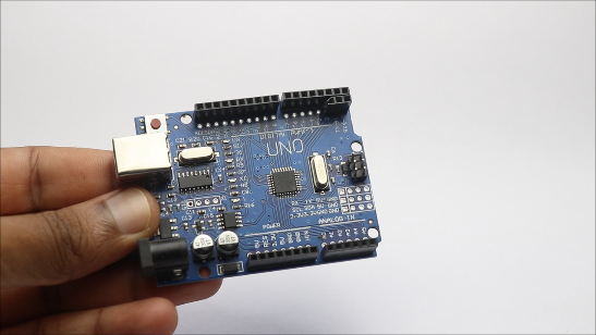
Arduino Uno from here
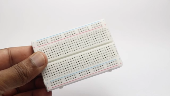
Breadboard
Jumper Cables for connection
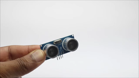
HCSR-04 Sensor(ultrasonic sensor)
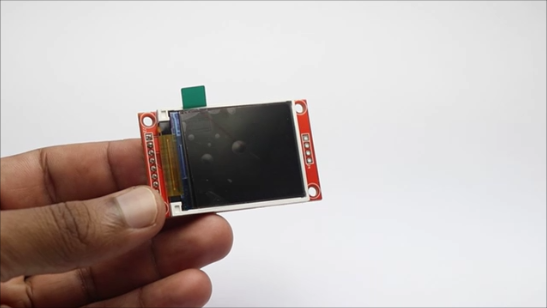
TFT Lcd display
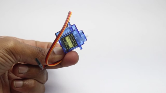
Micro servo
Arduino IDE
Programming Cable
Sheet of cardboard
Optional materials
3D printer
PLA filament
Cura slicer
Circuit Building


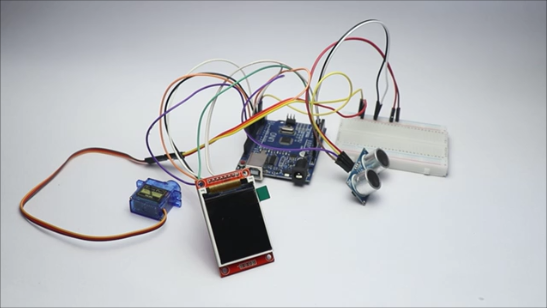
To begin with, let me connect the electronics and later upload the program. The circuit may seem complex at the beginning but trust me this is not as difficult as you think.
To break down the connections, I will explain the circuit one after the other
There are 3 main components in this circuit, the LCD, Ultrasonic Sensor and the servo and i will explain the connections one after the other.
Ultrasonic Sensor or the HC-SR04
VCC to 5V pin on the uno and GND to GND
TRIG to Digital Pin 9, whereas the ECHO pin to Digital Pin 10
Servo Motor connections
VCC or the red wire is connect to 5V and the Ground is for GND
Signal pin of the servo to D6
TFT Display module connections
VCC to 5V and Ground to GND
CS to D10 (Chip Select)
RESET to D8
A0 to D9
SDA to D11 and SCK to D13
After all these connections are complete connect the uno board to computr using the programming cable and use the below given program inside your ide
Only change that you need to make isnide IDE is the type of board and the port type.
Click on the upload button and you are good to go, after the program is done uploading the lcd starts to show and the servo should start to move, Now it is confirmed that the circuit is working fine.
You can also replace this open circuit with a simple PCB, Complete your electronic projects in the best way from PCBWay
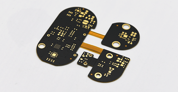
Why them? They have provided me with the best PCB, and the quality is just amazing compared to other providers in the market. They also have Color PCB printing check it out
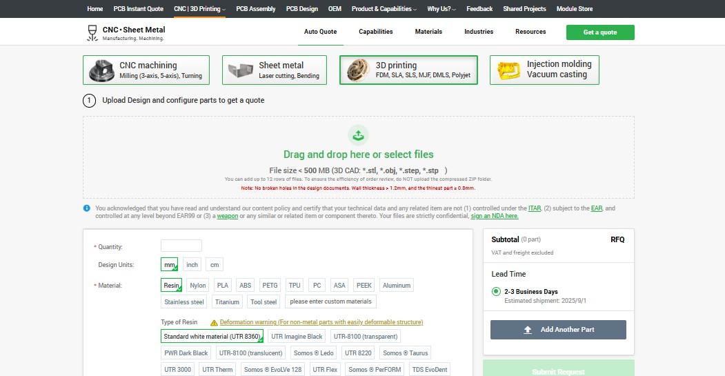
They are now offering crazy discounts if you are using their 3d printing service, For prints over 64g, the discount is equivalent to 20%–80% grab it here
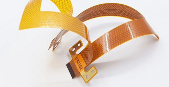
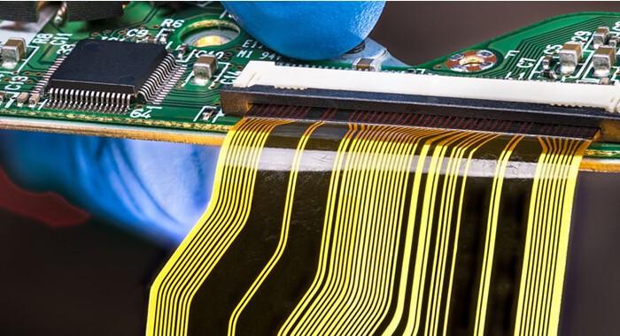
A revolutionary solution that combines the best of both rigid and flexible circuitry to elevate your electronic projects to new heights.
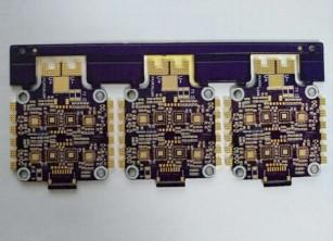
They also offering great prices for purple soldermask, As you know purple pcb are very expensive but not anymore, Check this out.
PCBA & Online quote available with 24hr delivery services
Their expertise in advanced manufacturing techniques offers seamless integration of rigid and flexible components, ensuring enhanced reliability, durability, and space-saving benefits.
Downloads
Design and Slicing


Like i said in the very beginning there is no one single rule that you have to follow the exact same project model like i did.
In case if you think this is the best setup you can simply follow the setup like i do.
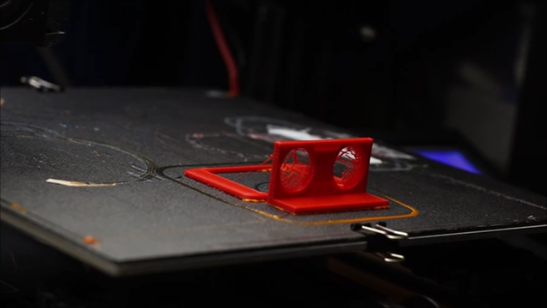
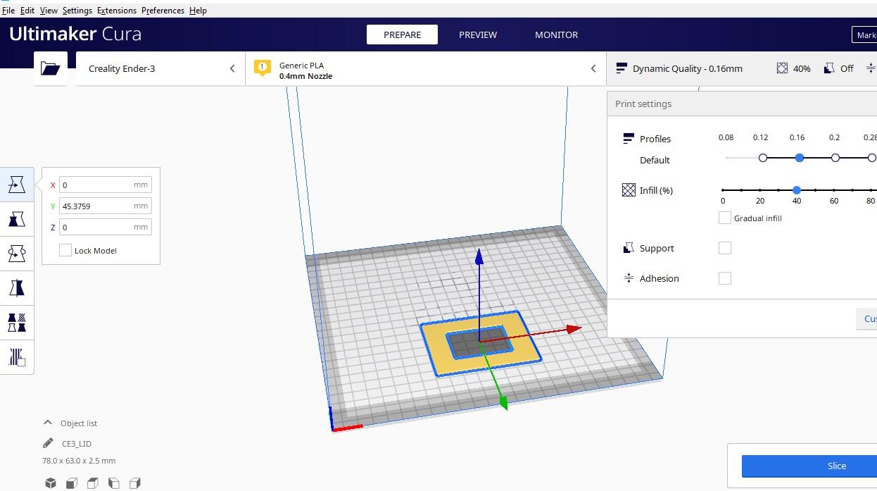
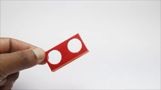
For the ultrasonic sensor casing i will design a simple object that fits the sensor and export it to cura and slice with the 30% infill with no rafts or the supports.
Later 3d print with the choice of color of your pla filament, I chose red.
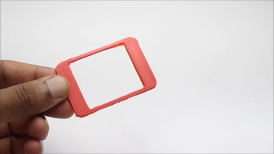
Now for the LCD display holder i simply designed a rectangular thing with a hole at the center, this will hold the LCD module safely in the base.
There was no need of using any supports at the time of print since there are no overhangs.
Dont have a 3d printer?
Nothing to worry my dear hobbyists there are other options also, all you have to do is use cardboard to make these frames.
If you have a standard components just make a note of their measurements and then you can make these holders for the respective components.
After you have all the 3d printed components ready we can head over to assembling the components.
Components Assembly

I will start by placing the electronics in an order so when i place this on the sheet of cardboard it will be very easier and the risk of wires getting disconnected comes down to large extent.
The ultrasonic sensor frame is connected to the hcsr04 first and then to the bottom of this i connected servo horns so this can be connect to servo shaft easily.
Later connect the frame to the TFT screen, This makes the screen safe from any damages.
Now place all the components in the cardboard and use double sided adhesive to keep the electronics in place.
Arduino uno should be placed like i showed in these steps this is because by keeping like this if you want to make any changes to the program the board pins are easily accessible.
After you keep all the components the project is ready for testing and we can see that in the next step.
Finishing and Using

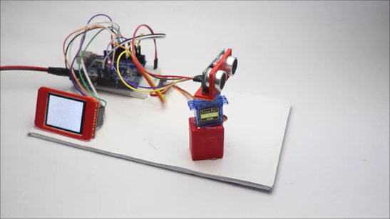
To elevate the height i used a small piece of 3d printed object, you can replace with other materials also.
Make sure that the servo is sweeping without any obstructions like for example the wires should not interupt the movement.
Set the angle manually of the ultrasonic sensor so that the 180 degreee is covered and these areas are completely free from the components in the board.
Follow the placement of components like i did so that you will get great results from the setup.
Using this is actually very fun and interesting, all you have to do is connect the USB cable to Uno first and the other end to any USB power source in my case I will be using a mobile power bank.
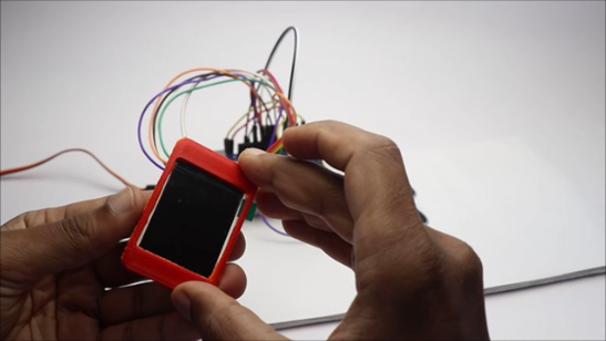
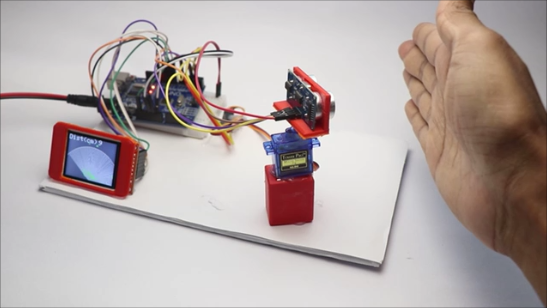
To test the project, as soon as the power is connected the TFT screen will turn on and then the servo will start to move.
Place your hand in front of the ultrasonic sensor and you should be seeing the green dots on the screen this means that something is being detected on the radar zone and the same happens on the actual radar too.
Try placing the different objects and you can also adjust the length of the object and the same can be seen on the display also.
This was all about this project, if you have any questions consider watching this video first
Working Video

Are you feeling you missed something in the process? Not to worry in this video not only i have the build tutorial but also a working video of this project.
Thank you for showing interest and making till here, If you have any questions we have comments box.
I would be really willing to see you guys making this project, Post your make in the i made it section and let other see your project.
Alright then this was all about this project, see you all in the other project, Have a great day.