How to Modify Your EM Pinball Machine -Doodle Bug Edition
by kojis92 in Circuits > Reuse
125 Views, 0 Favorites, 0 Comments
How to Modify Your EM Pinball Machine -Doodle Bug Edition
My hope with this 'able is to add comfort for those looking to make some adjustments to their EM pinball machine. The mechanical nature and documented circuit of these machines makes them highly compatible for not only future maintenance, but also with making adjustments, adding mechanisms, scoring DIY and so forth.
Although most machines especially amongst different manufactures will have differences, hopefully the maker will be able to extract some of the basic concepts and ideas from this article.
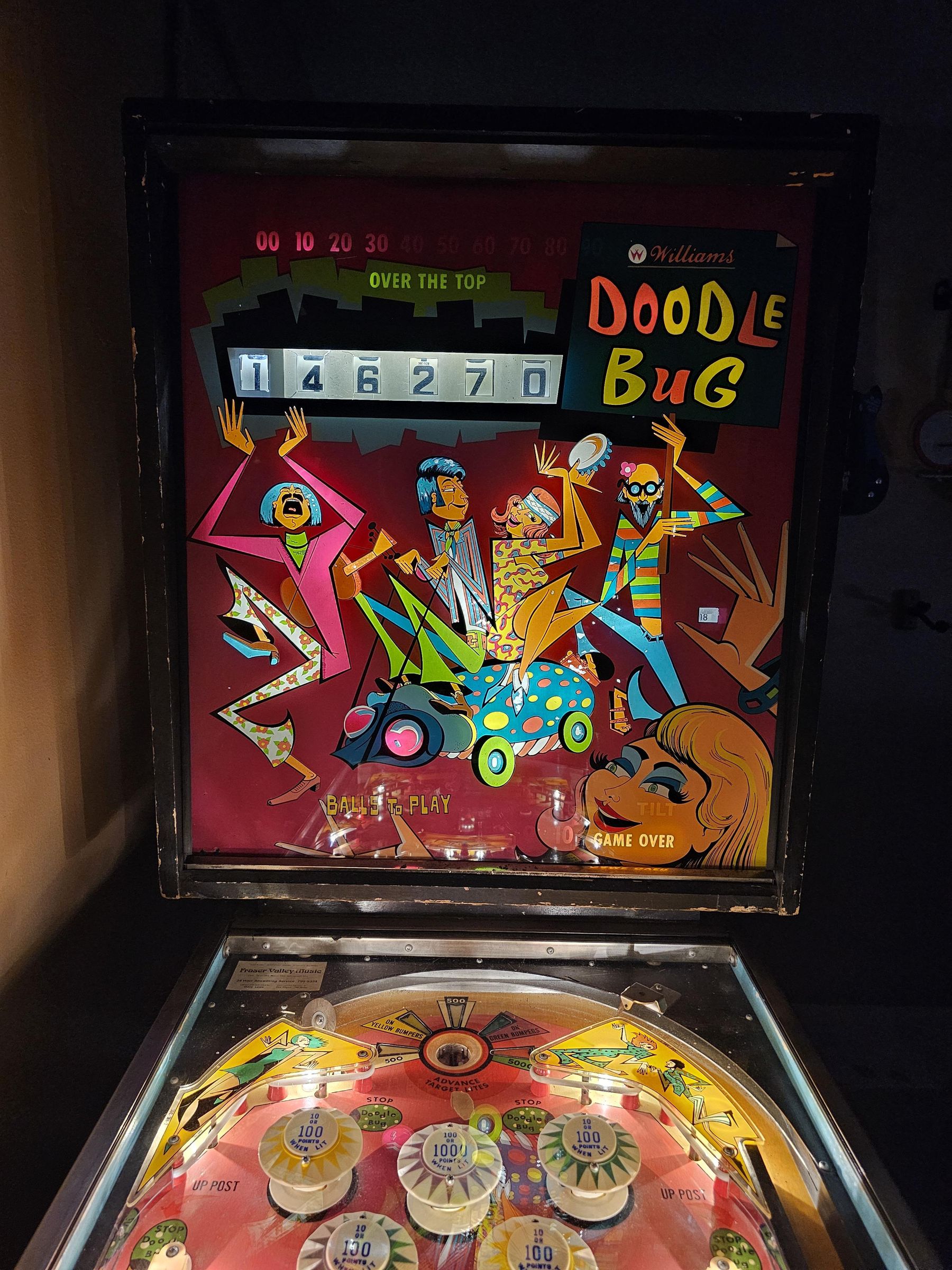
In this case, we have a lovely Doodle bug pinball machine. This is an excellent machine from the 70s, which is loaded with iconic pinball features such as a controlled post save between flippers, and a right gate to the shooter lane, light able yellow bumpers, light able green bumpers, unique "untrappable" flipper configuration, a 5k scoring saucer, and on top of this, we have a really interesting doodle bug mechanism, which allows the player to start the bug, which trips a controlled sequence of a ball moving up and down within a sunken area near the middle of the playfield. This then triggers an associated amount of points per switch, typically making multiple score advances per second. The level of scoring is dictated by how far a player has advanced the doodle, and in the case of the last level (10k), as you can imagine the potential score can begin to very conceivably pass the 100k thresholds in the rare case that a player is able to advance this far.
When told about the prototype version of this game, I was quite intrigued. I was told that the prototype in fact had an additional score reel that was later replaced in production machines with a lighted digit and over the top relay which would allow a maximum displayed score of 199,999 (over the top then indicating that you had in fact made or exceeded 200k). In the case of the prototype, the maximum displayed score would be 999,999 and it still also had 1,000,000 light in place of the text "Over the top".
As the general placement of the scoring window and over the top on the backglass is compatible with the prototype, it opens the door for a realistic modification to be able to facilitate the same functionality.
In addition, to ensure the game is fit for fair competition we will make another adjustment to the saucer feature, to ensure that we start at the left most 500 pt location. (Originally a player may play this game and this saucer value will be "random" as such, some players may start with this lit at 5k, which would in fact give them an advantage).
Check out a preview of the work here:
Supplies
Although this guide has been written in a general sense to make people comfortable with the idea of making modifications to EM pinball machines, the specific example(s) will require the following parts and supplies:
- Original doodle bug schematic: (At the time of publication, this is still available from: ipdb.org)
- A complete score reel unit (If adding a score reel). Ensure the score reel has a functional circuit board with 11 solder tabs at the top if recreating prototype replay level functionality is important to you.
- Wire (the gauge of wire needed will depend on the circuit. It's best to find the fuse on the circuit, so for example, if there is a 15amp fuse, then targeting a 12-14 gauge wire should be acceptable). If unsure, 12 should handle most EM pinball applications.
- Additional mini contact leaf switches to be added to the score reset, along with two longer blades for the saucer step match unit cam. PS: It's generally most sensible to buy used suitable relay assemblies where you may harvest these parts as needed. I will try to add the part numbers here later.
- Optional, an additional score relay unit
- 3D printed files to be printed (see step 4)
- All the typical servicing tools, soldering iron, solder, flux, cleaning and leaf adjustment tools, philips screwdrivers, 3/8" socket, coping saw (or other grinder), etc.
More Head Space - Cutting and Drilling Best Done in the Outside World
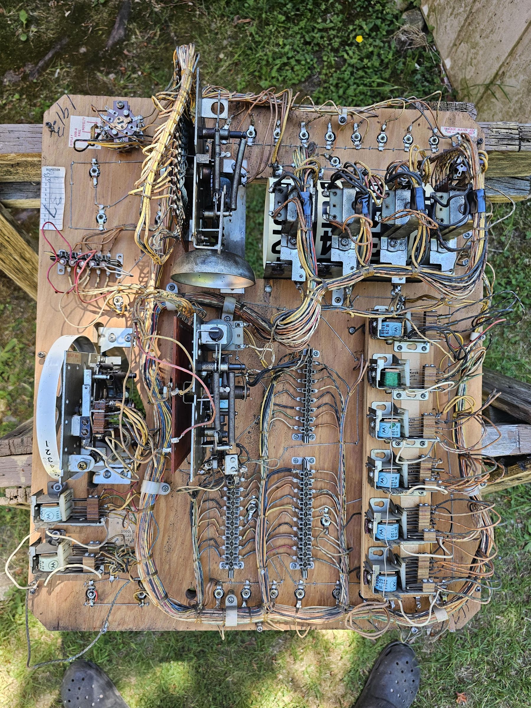
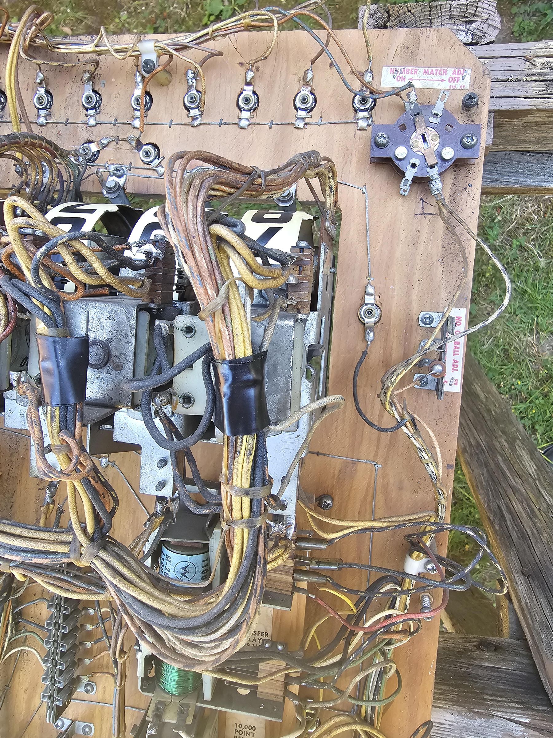
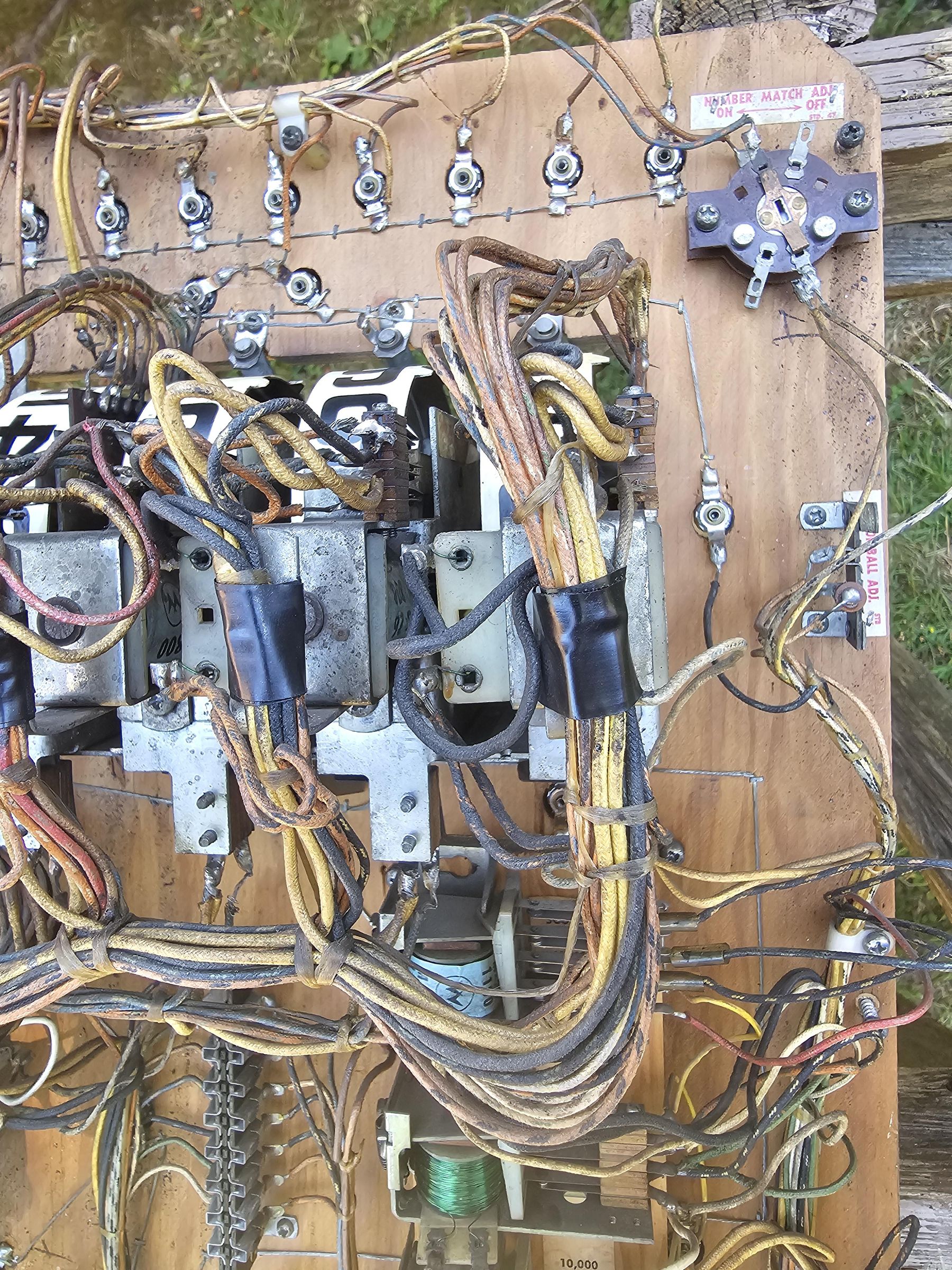
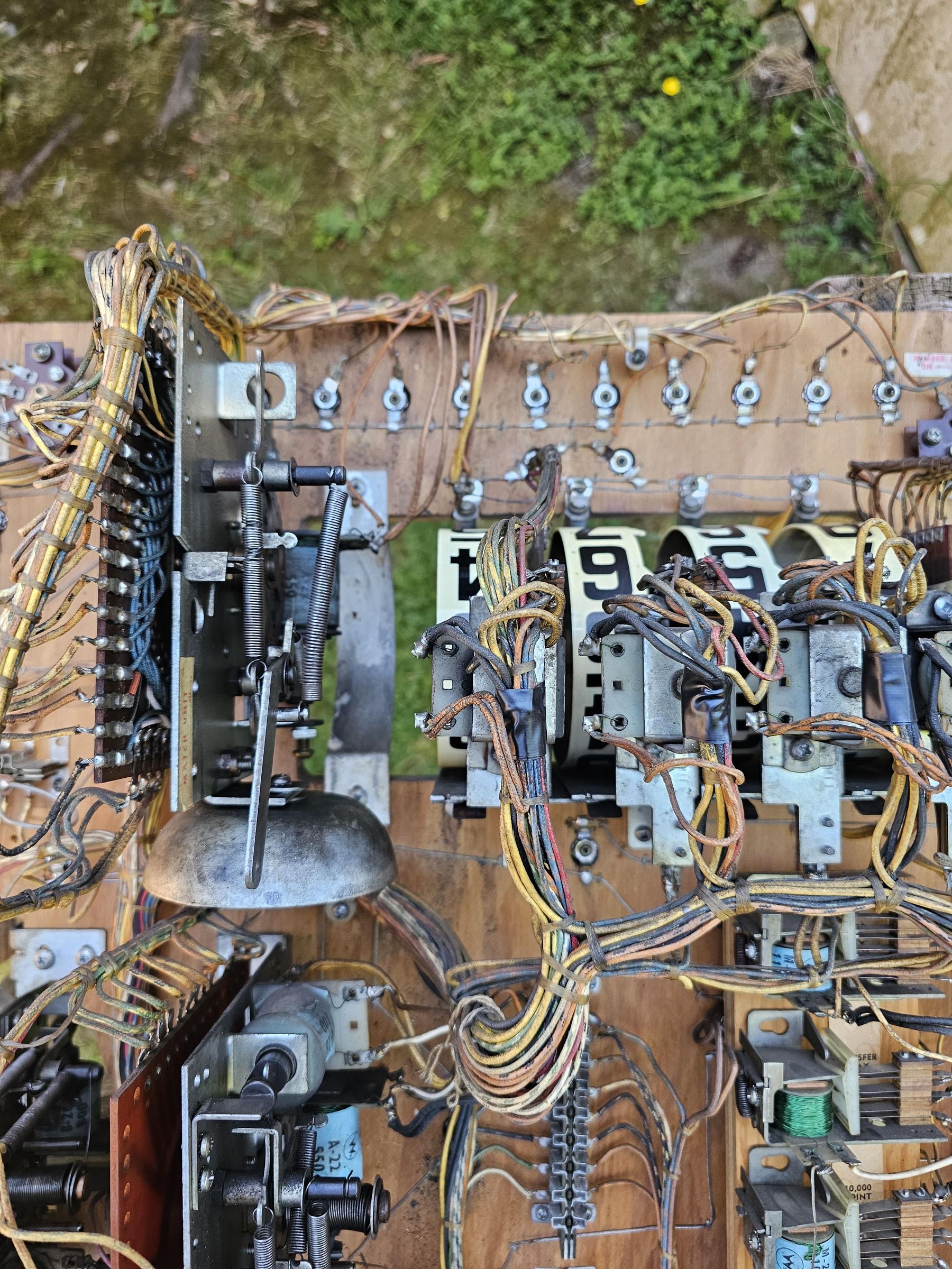
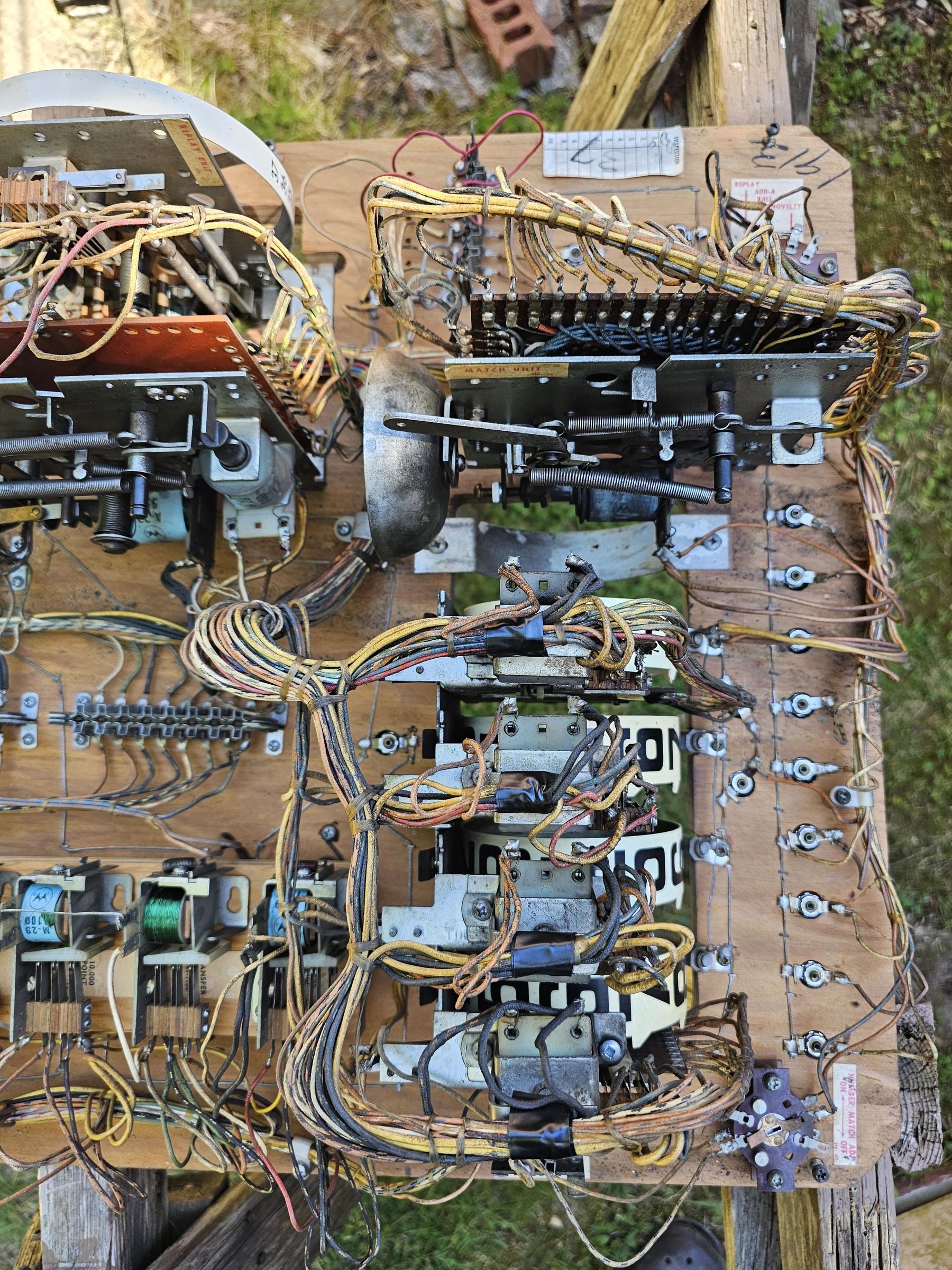
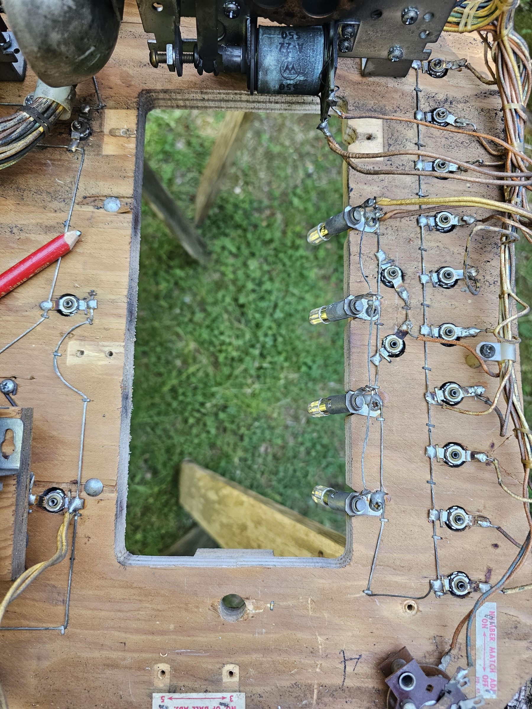
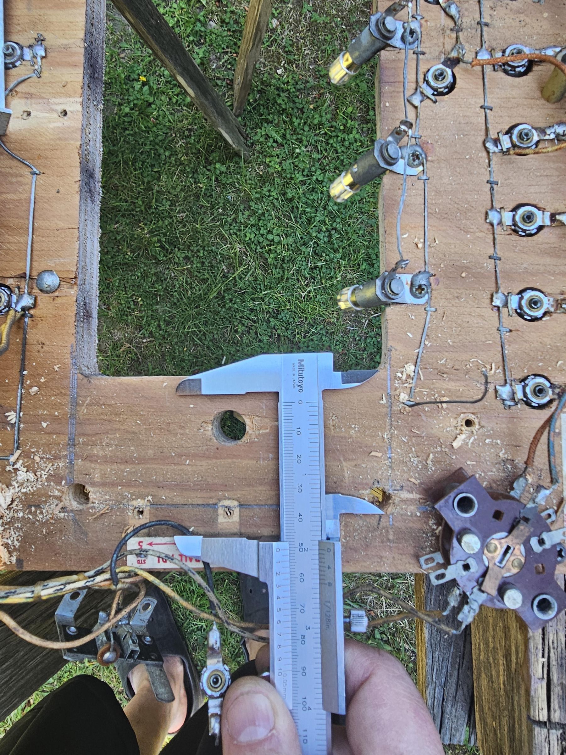
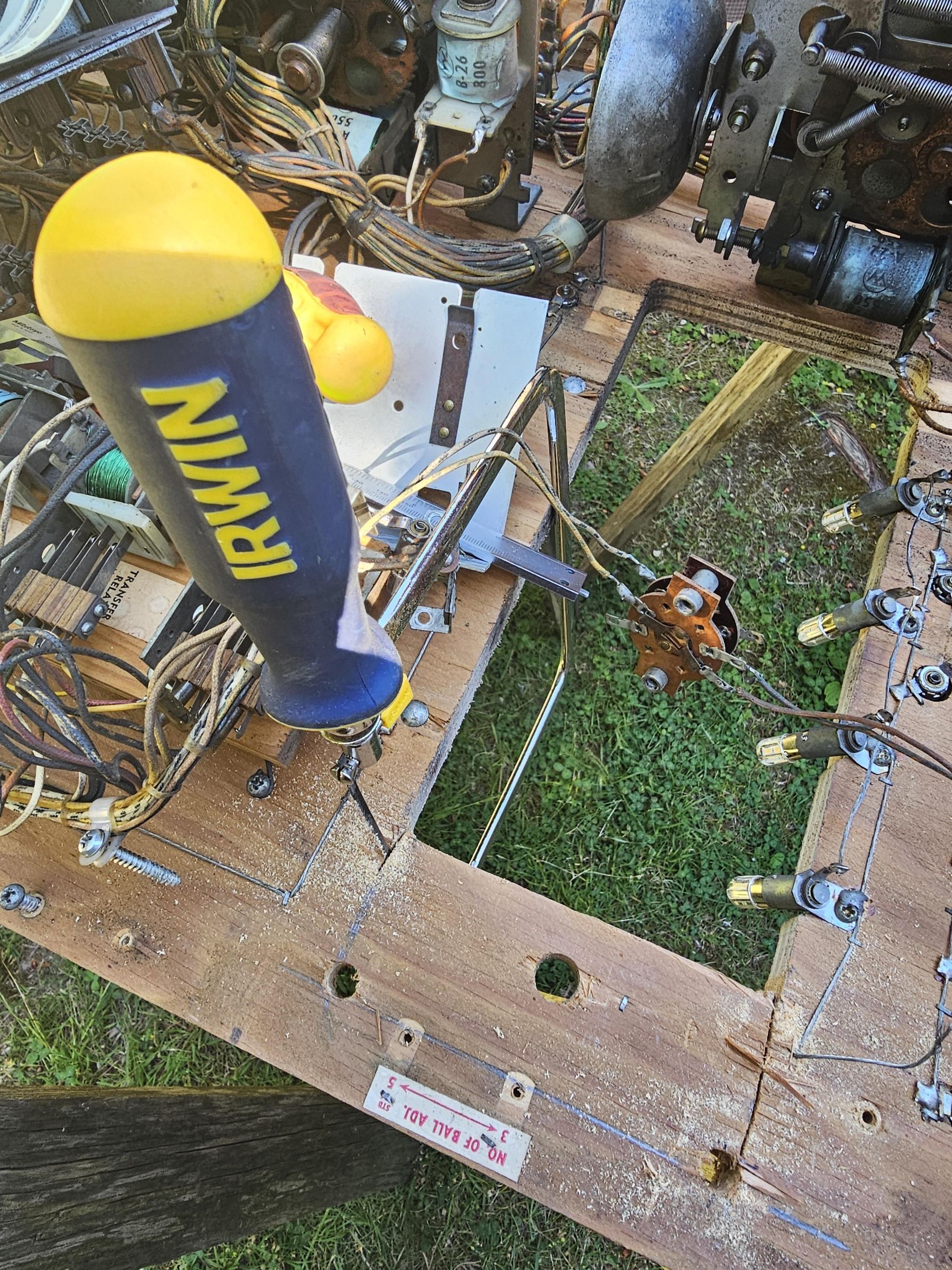
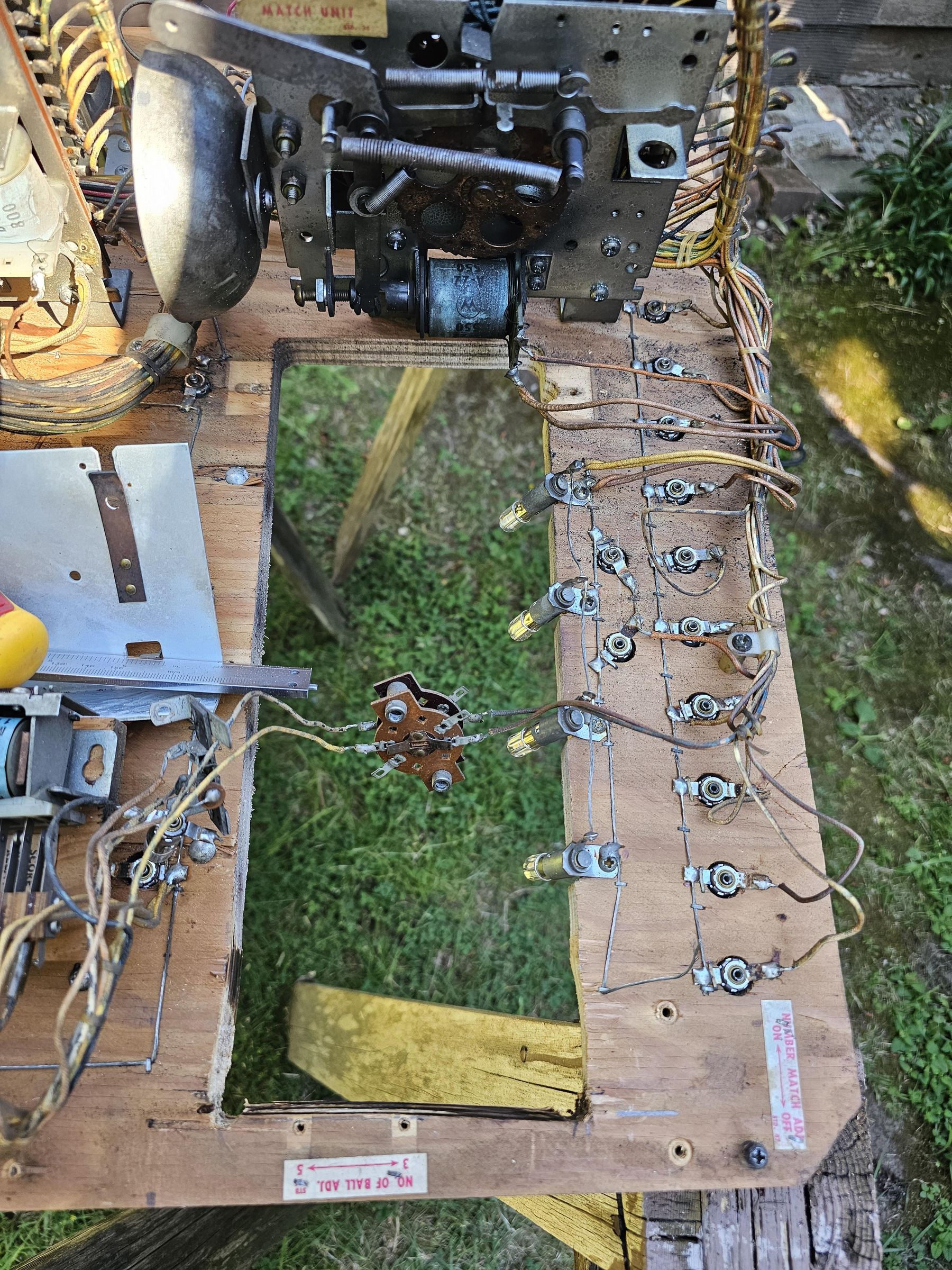
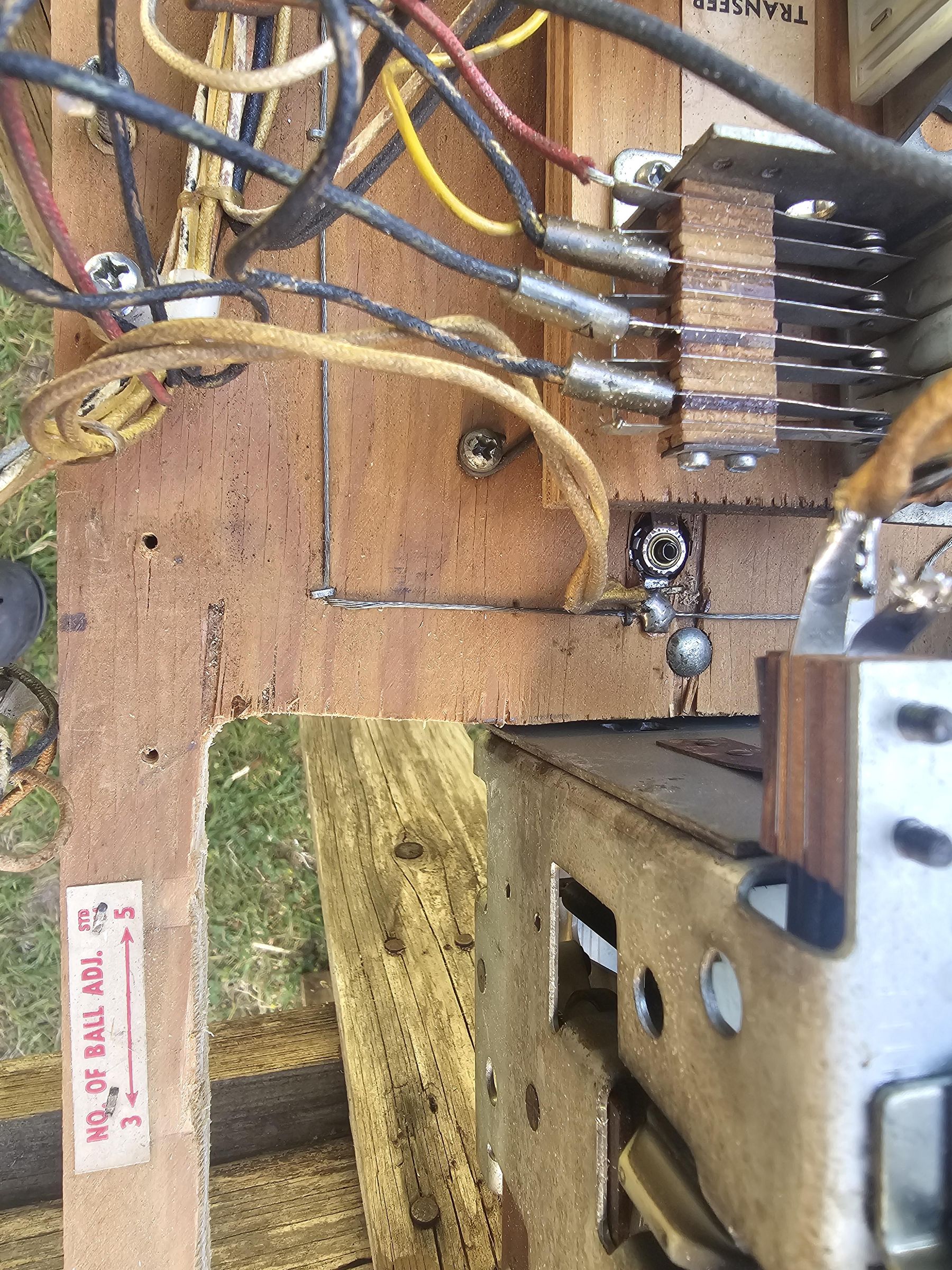
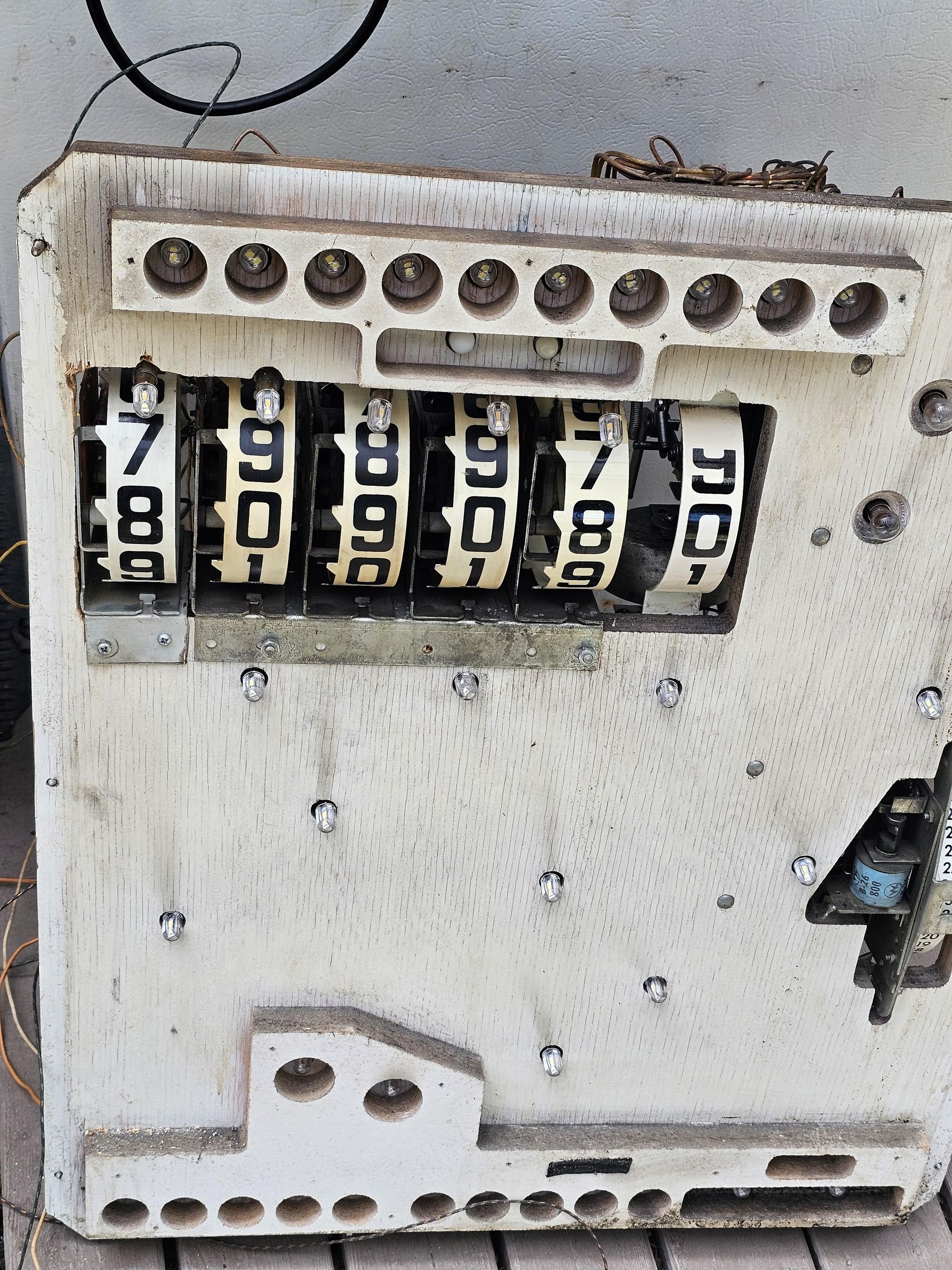
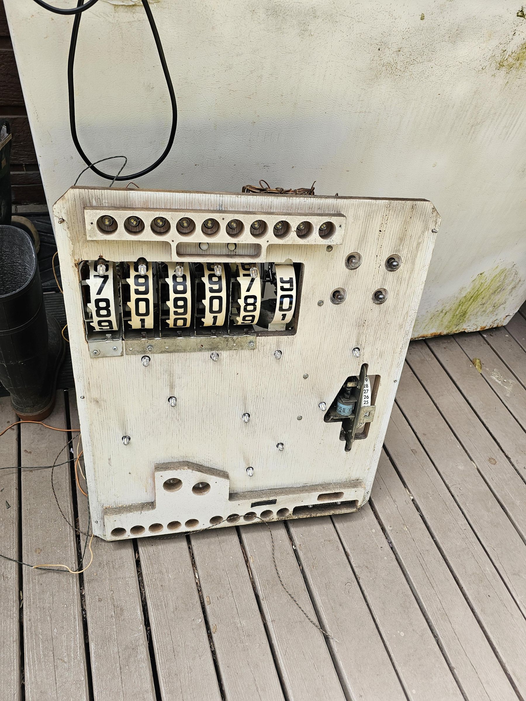
Unfortunately there is no way around this. We physically need to cut out the old lamp socket area of the backbox. Ensure you take a lot of photos so you can know where the various parts get mounted. In my case, I ended up need to come back to it and cut more of the side. A coping saw worked quite well for this, alternatively, removing everything and cutting with a table saw or router attachment would be another option. The entire head circuit can be detached by disconnecting the jones plug connectors, and removing ~ 6 screws to come apart from the cabinet trim.
Drilling the corners before hand and cutting straight to them worked pretty well.
The prototype backbox actually uses a 3 + 2 score reel bracket configuration. Unfortunately, the production doodle bug has everything on a 4 bank reel bracket. In my case, I had a 2 bank bracket on hand, so I just cut that in half with a angle grinder and used it to fix to the backbox for the 5th score reel addition. This required removal of the 100k lamp wiring, and slight repositioning of the 3-5 ball adjustment jack.
Re Mount in the Machine and Wiring
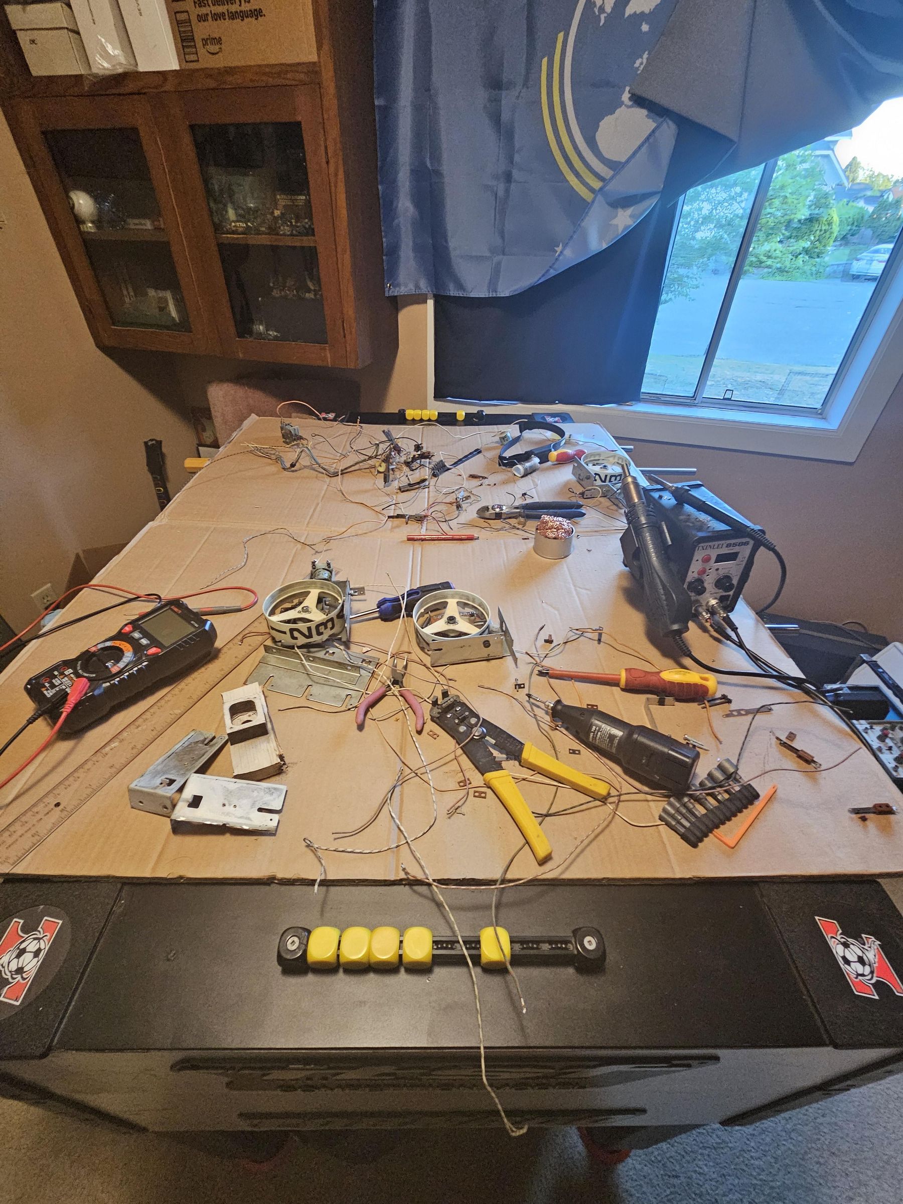
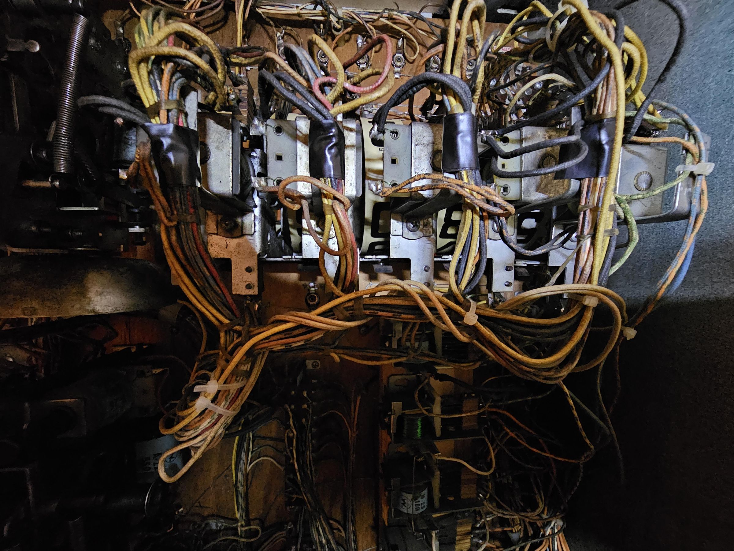
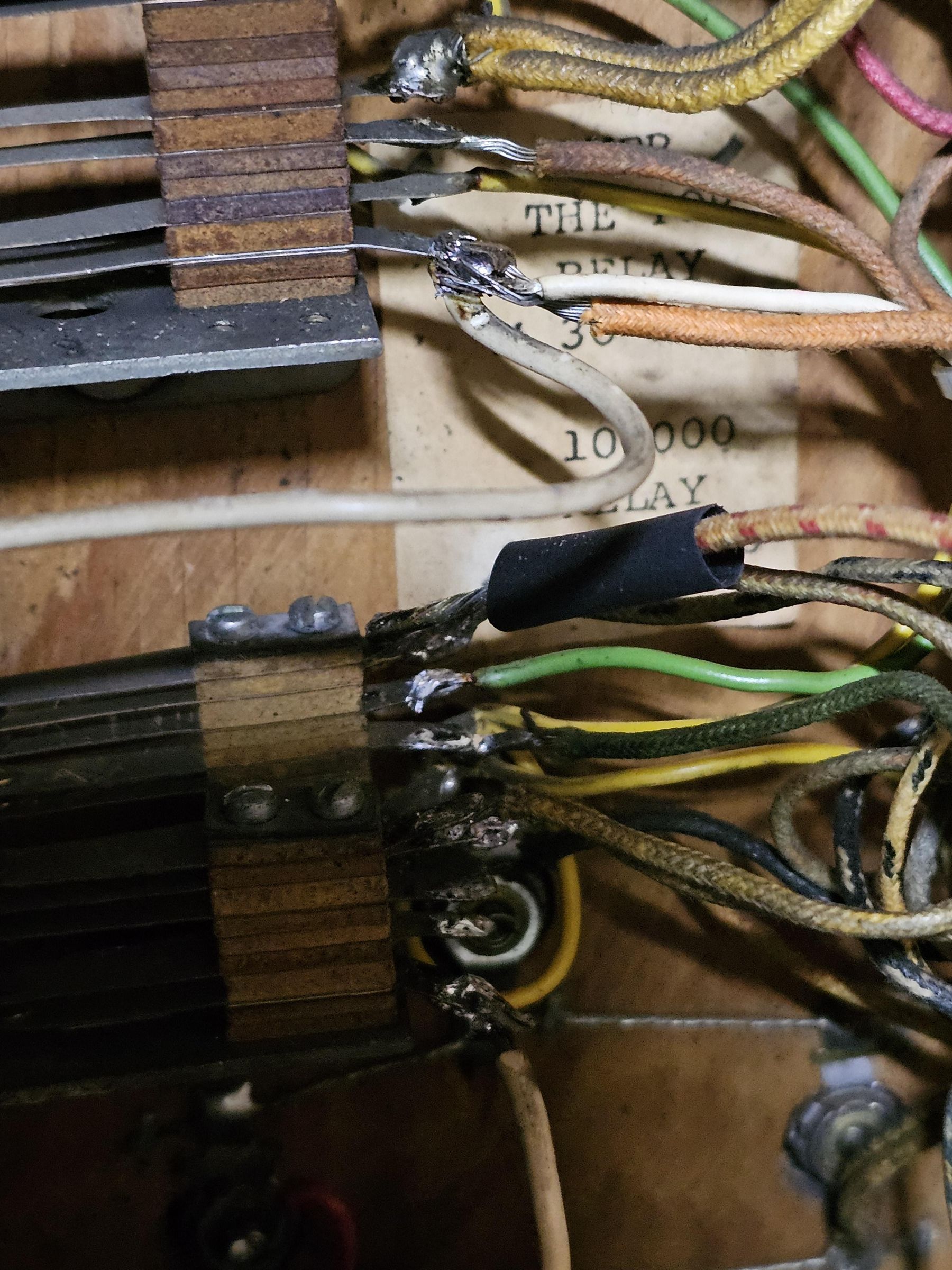
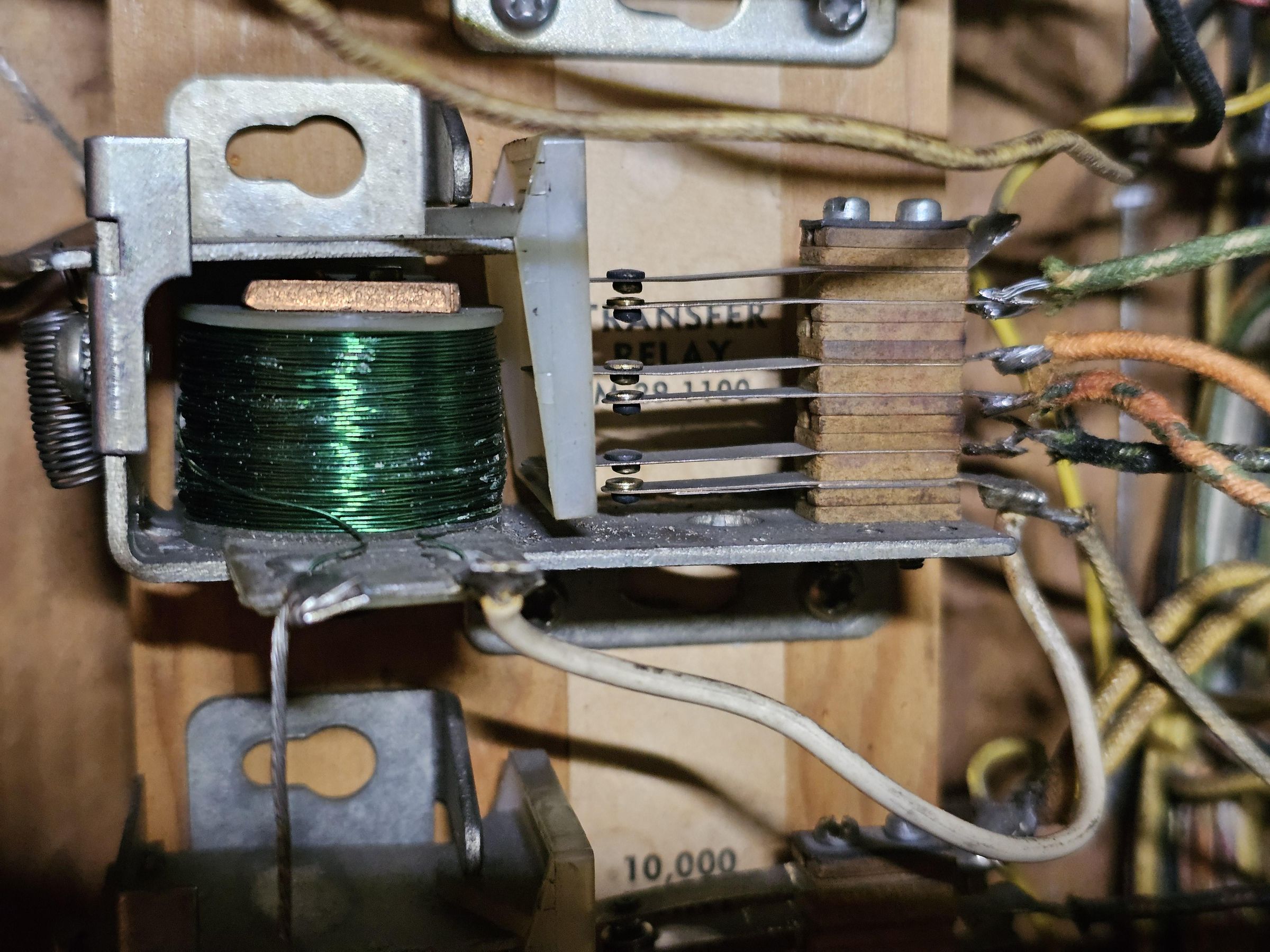
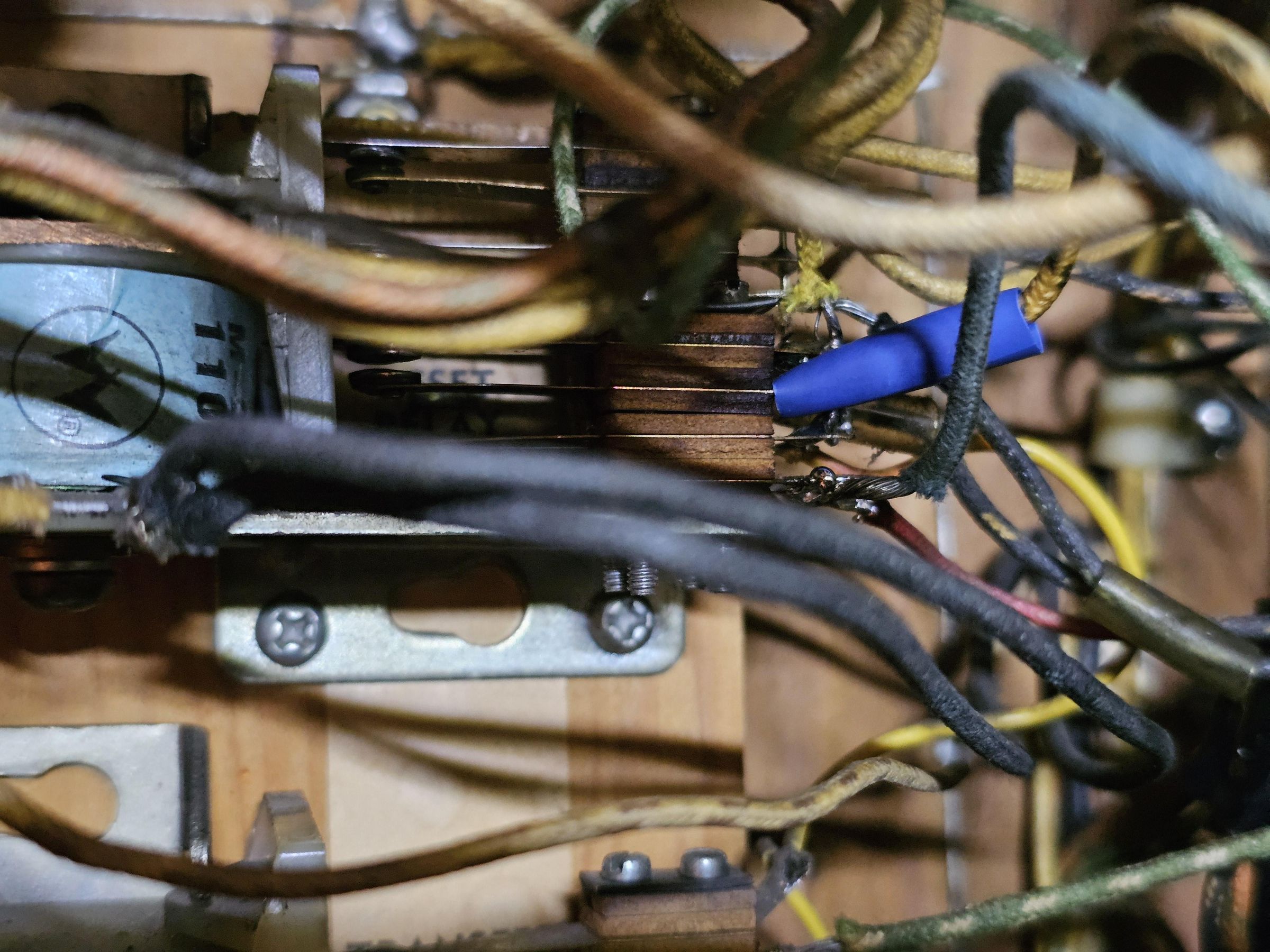
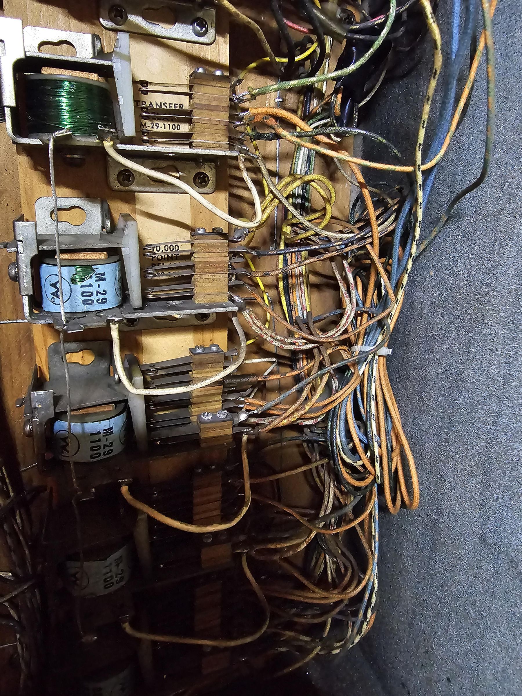
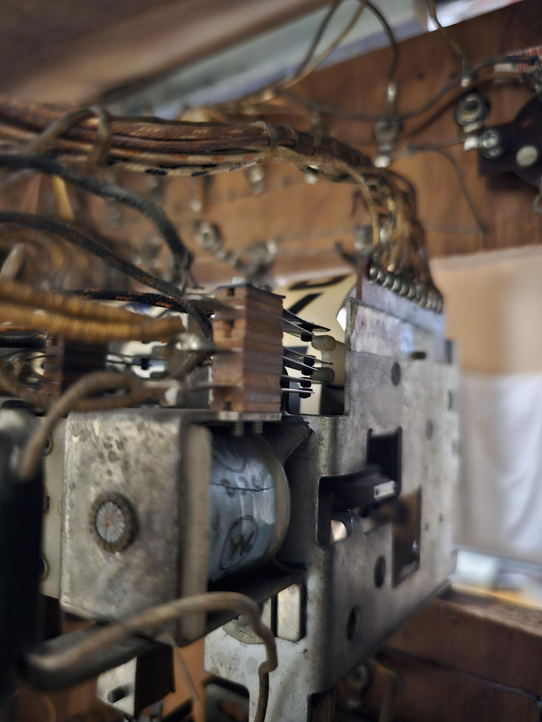
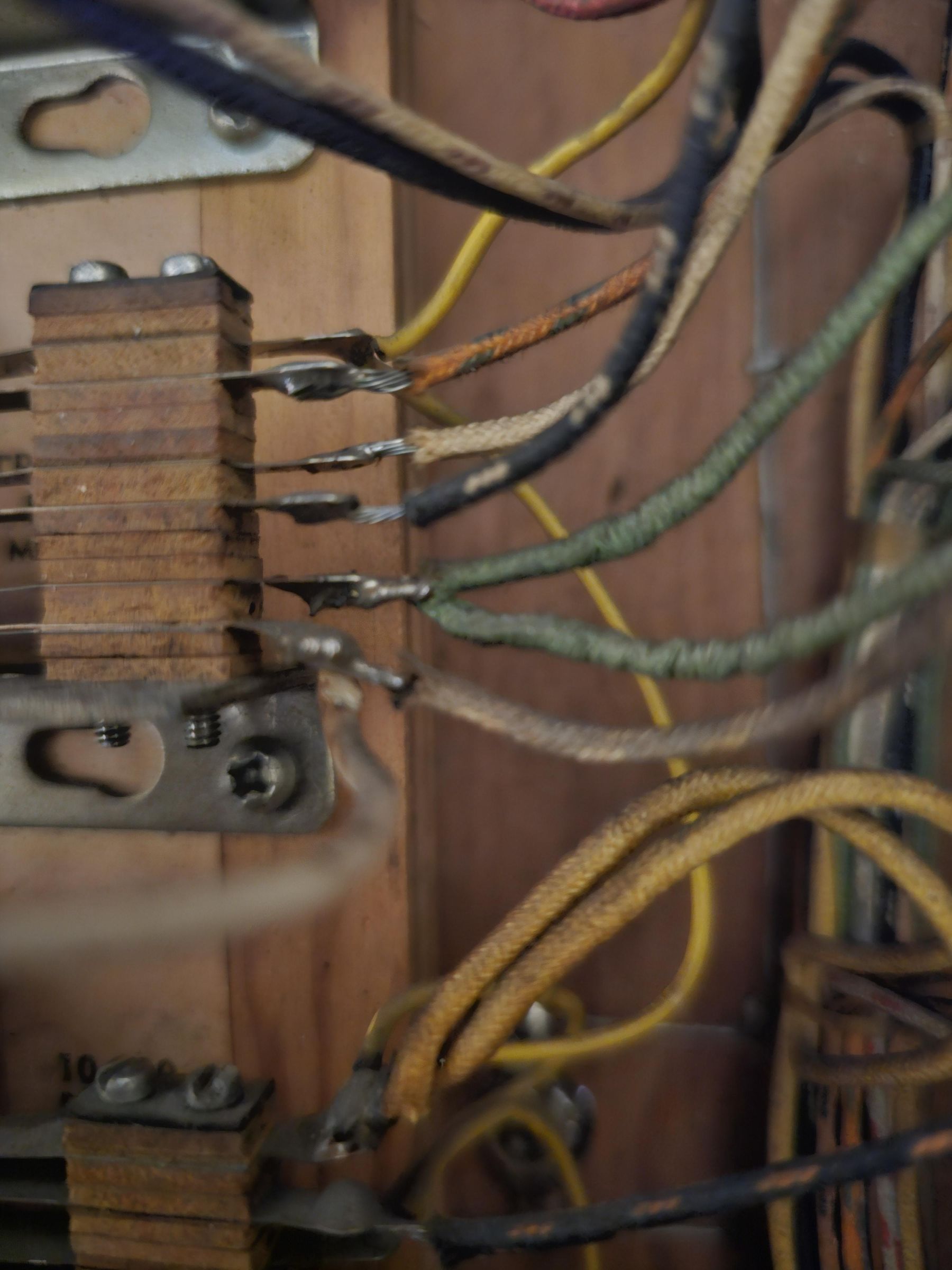
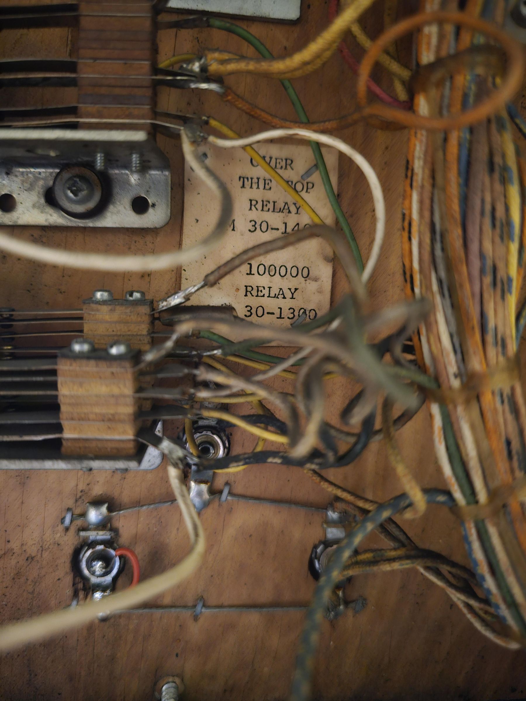
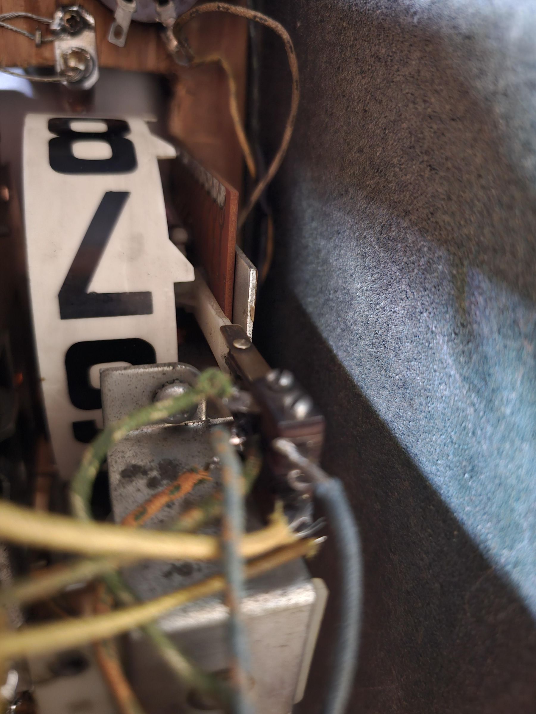
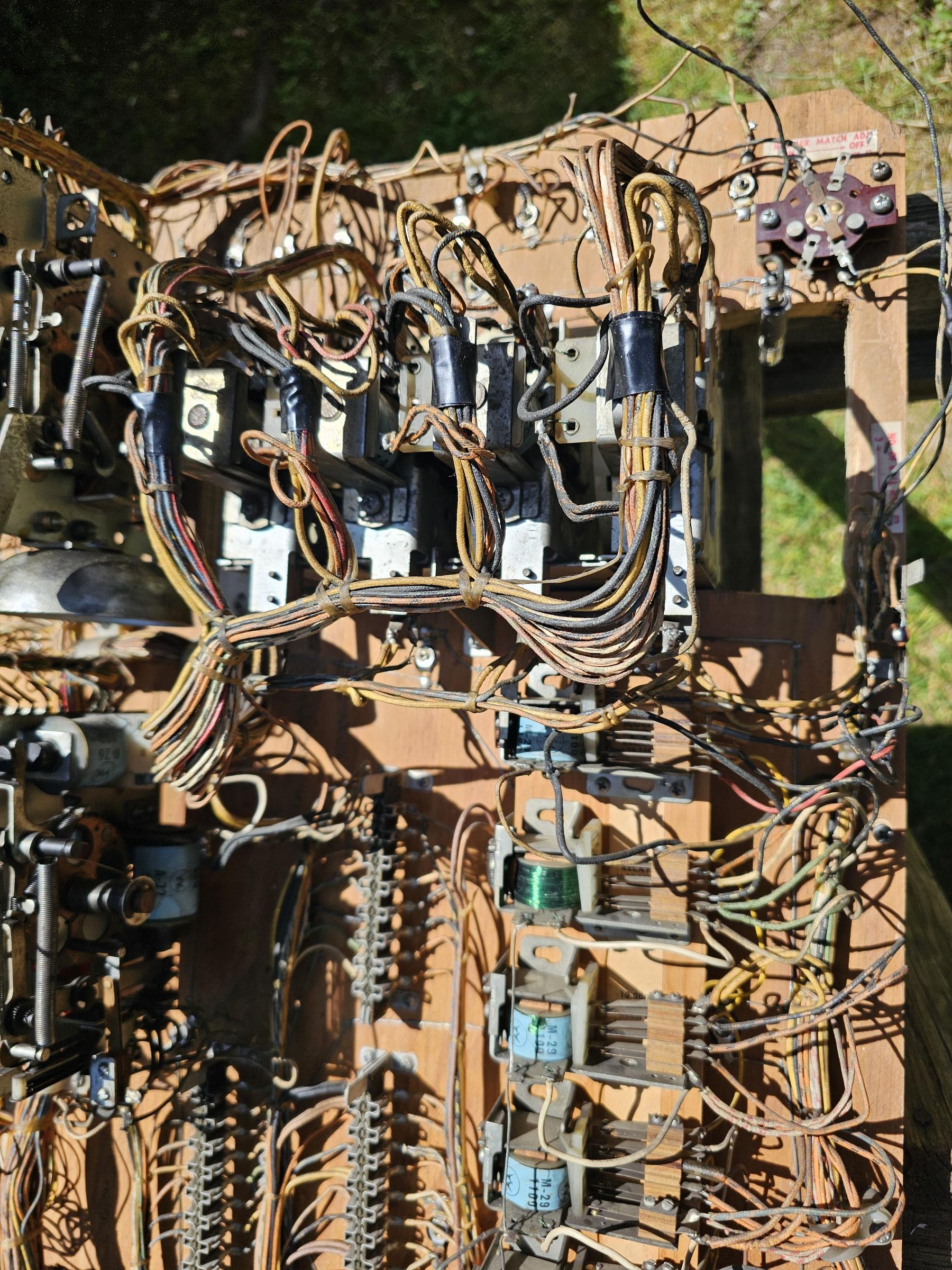
With the main head circuit re-attached, we will begin to make the necessary wiring additions. This modification of adding a score reel is very much a piggy back on the existing functionality.
At this point, for a doodle bug you have two paths. You could hijack and remove all functionality of the transfer relay / 100k relay. We technically will not need these, as a score reel with circuit board for replay scoring levels contains all the functionality we need. HOWEVER, I believe you could leave much of this functionality in place, and instead, just add a new relay for the 100k score reel. It's your choice. for me, I am going to re-use the transfer relay, and disconnect most of the leads and wrap them for future consideration.
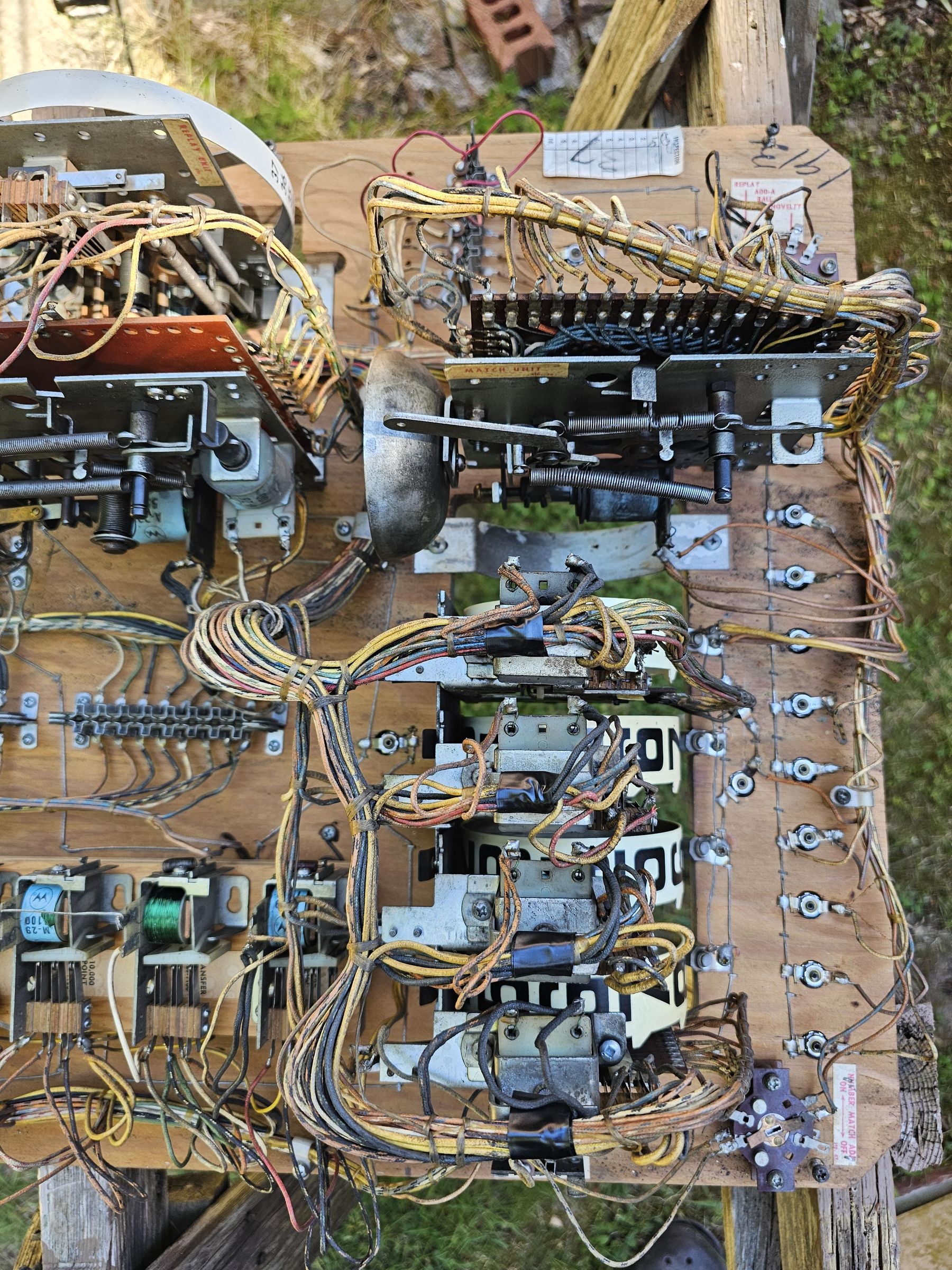
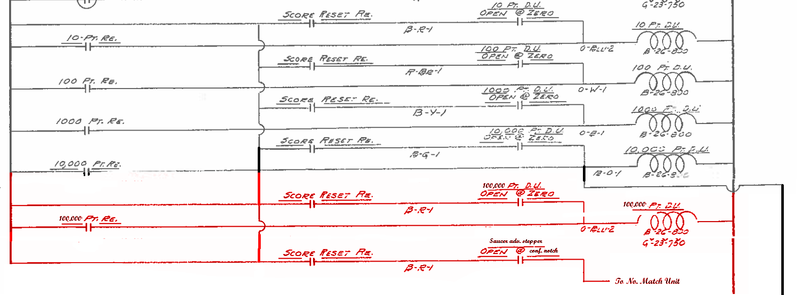
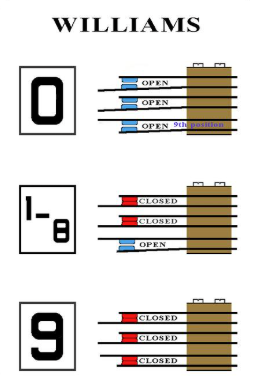
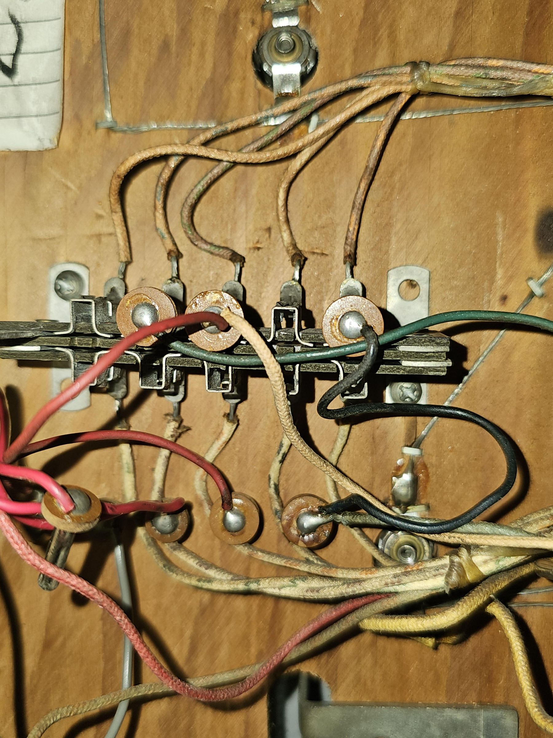
Unfortunately, the schematic additions are not sufficient to fully explain the wiring involved. In words, we are looking to carry forward the score reset runout (see 0-9 image attached). The top most switch will directly chain from the 1,000s drum unit of the same switch stack.
The middle 1-8 is the actual circuit that should go back to the score reset relay with new leaf switches added. Again, the circuit hear will resemble the other score reels on the reset leafs.
The bottom switch (9) is what we will use as our carry-over, and this is what will connect to the "over the top" relay directly.
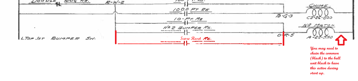
If you are moving ahead with the saucer scoring reset as well, you will again chain the same score reel reset sequence to this unit, with an additional set of leads for the top switch to this, and and additional set to go from the actual score reset relay. We'll cover that in the next step.
the rest of the circuit for the score reel will come down to an additional relay for the 100k unit. There is no playfield scoring for a 100k, so this will ALWAYS come from the 10k unit carry over. You should find a lead which connects the 10k carry over to the 100k relay on the other side of the backbox. This can be disconnected or re-used to rather pulse our 100k unit. In addition the 100k unit will require 3 switches, that will pulse the scoring as with the 10k unit. This unit will also include a carry over that will connect to the "Over the top" relay which will become out 1,000,000 for all intents and purposes. Due to the score reel functionality, we are superseding the production units double step relay, of the transfer unit and 100k relays, and as such I am re-using the transfer relay and switches for re-use in the modification.
Made It This Far, Now the Scary Part
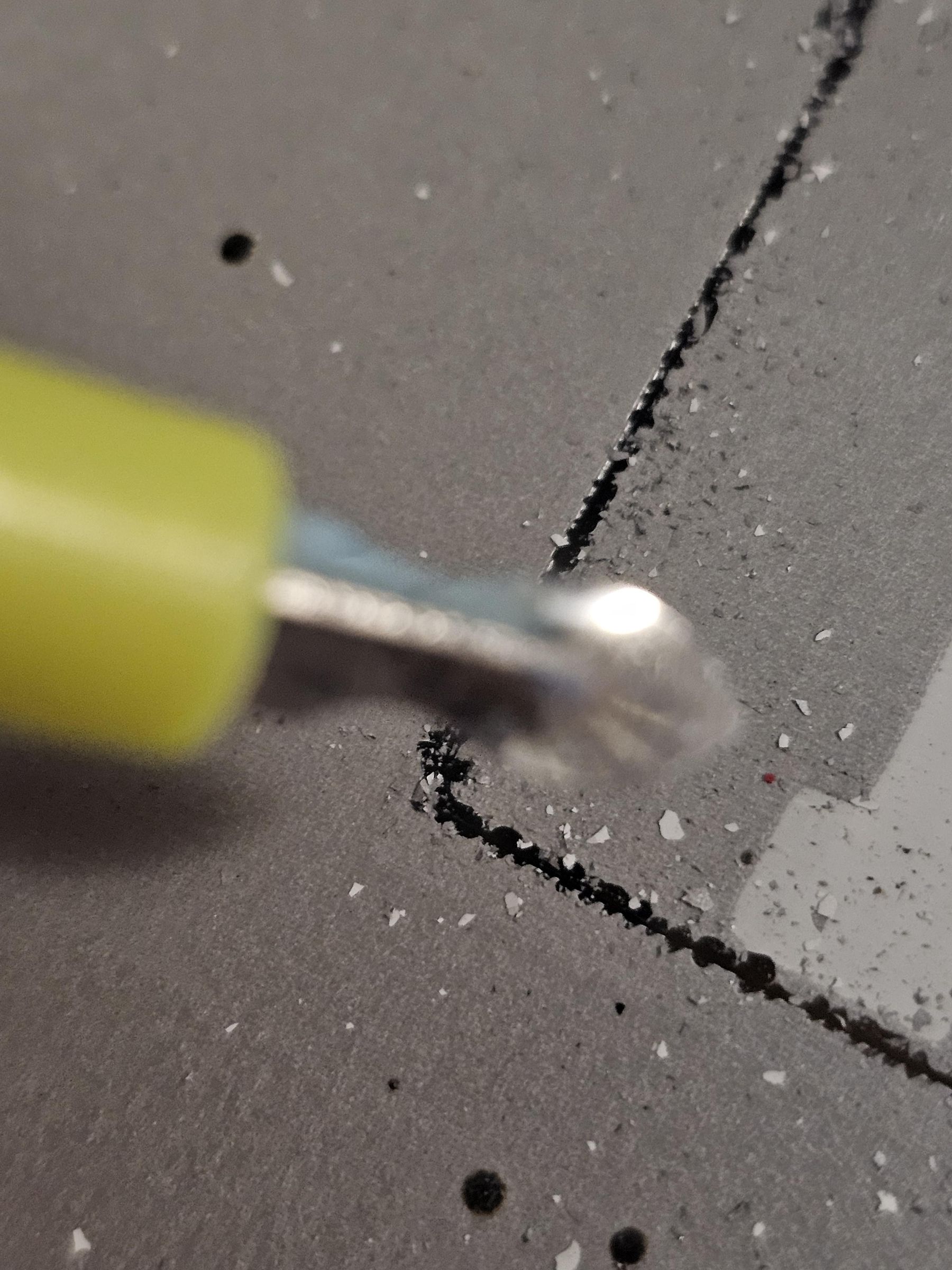
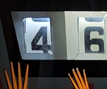

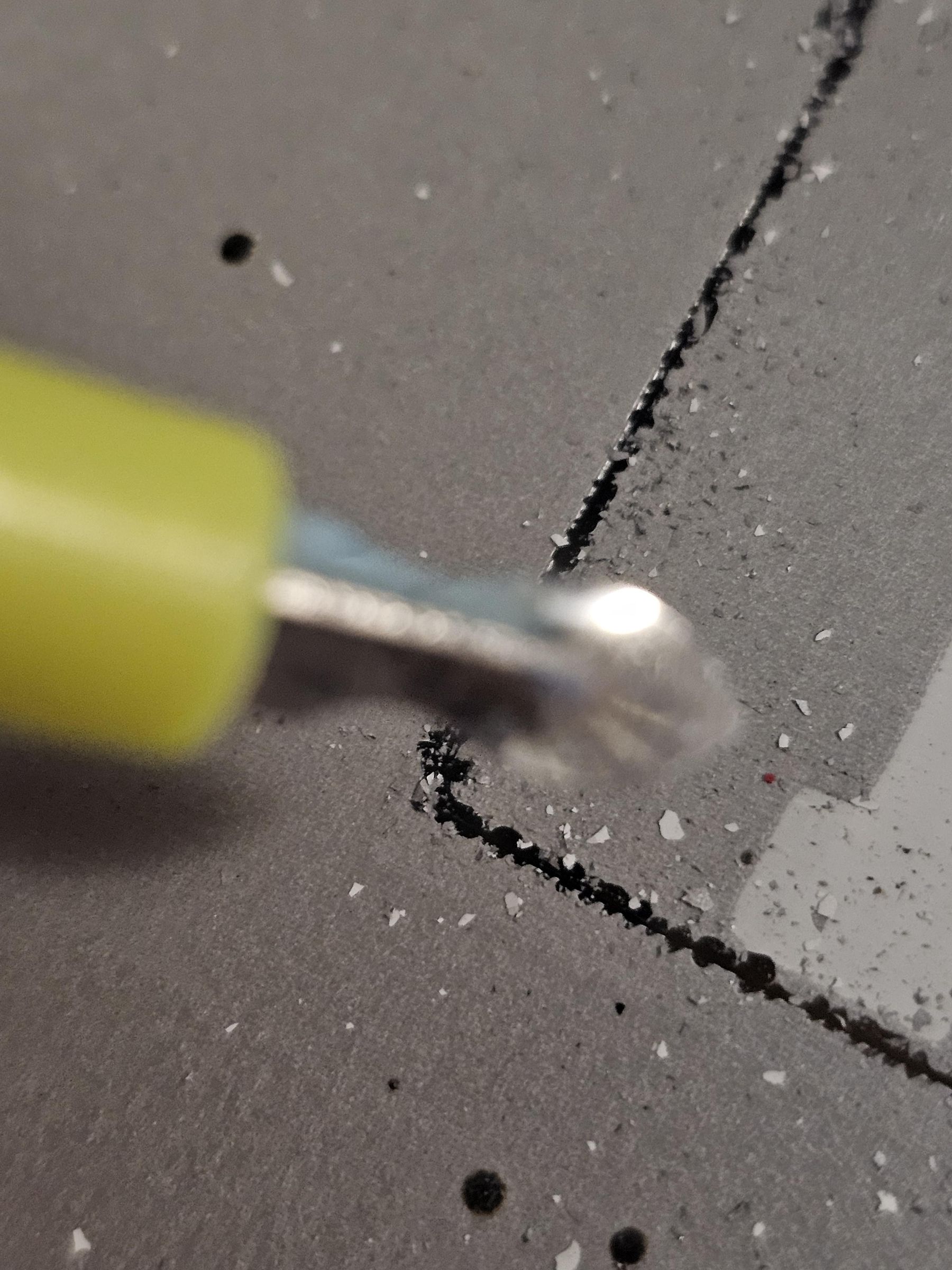
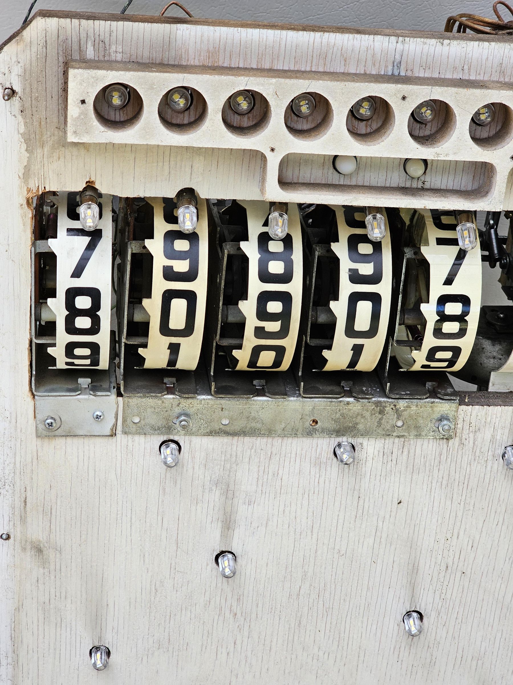
The original production backglass was inked over on this window, and displayed on a 1 that could light up. As we now have a real score REEL behind here, we need to remove this. I used a scraper to carefully try to etch away the mask layer. If you hold this to some light, you should be able to faintly see the outline where you are scraping. Not much we can do about changing "Over the top" to 1,000,000. I'm happy with "Over the top = 1,000,000". If you really want it perfect, have a BG specialist like BG Resto produce a prototype backglass for yourself. You deserve it!
The Saucer Scoring Dilemna
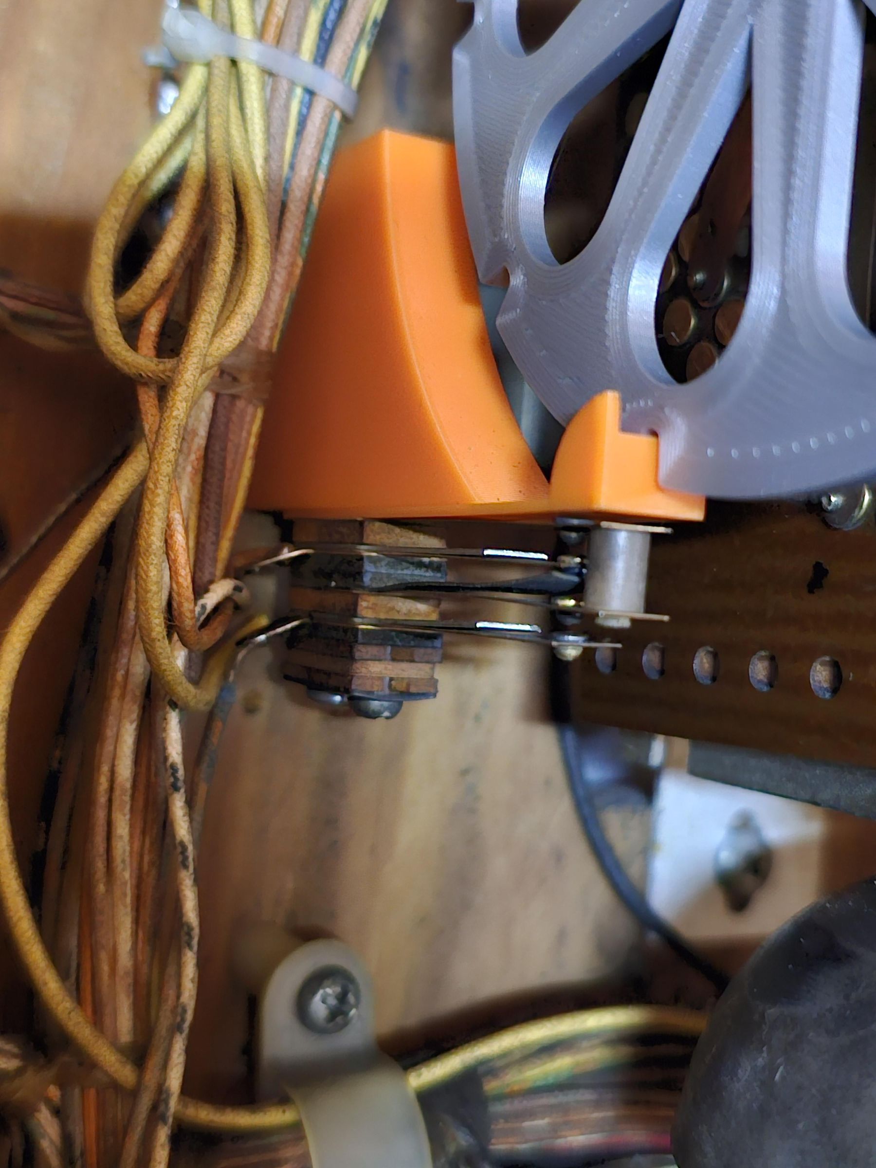
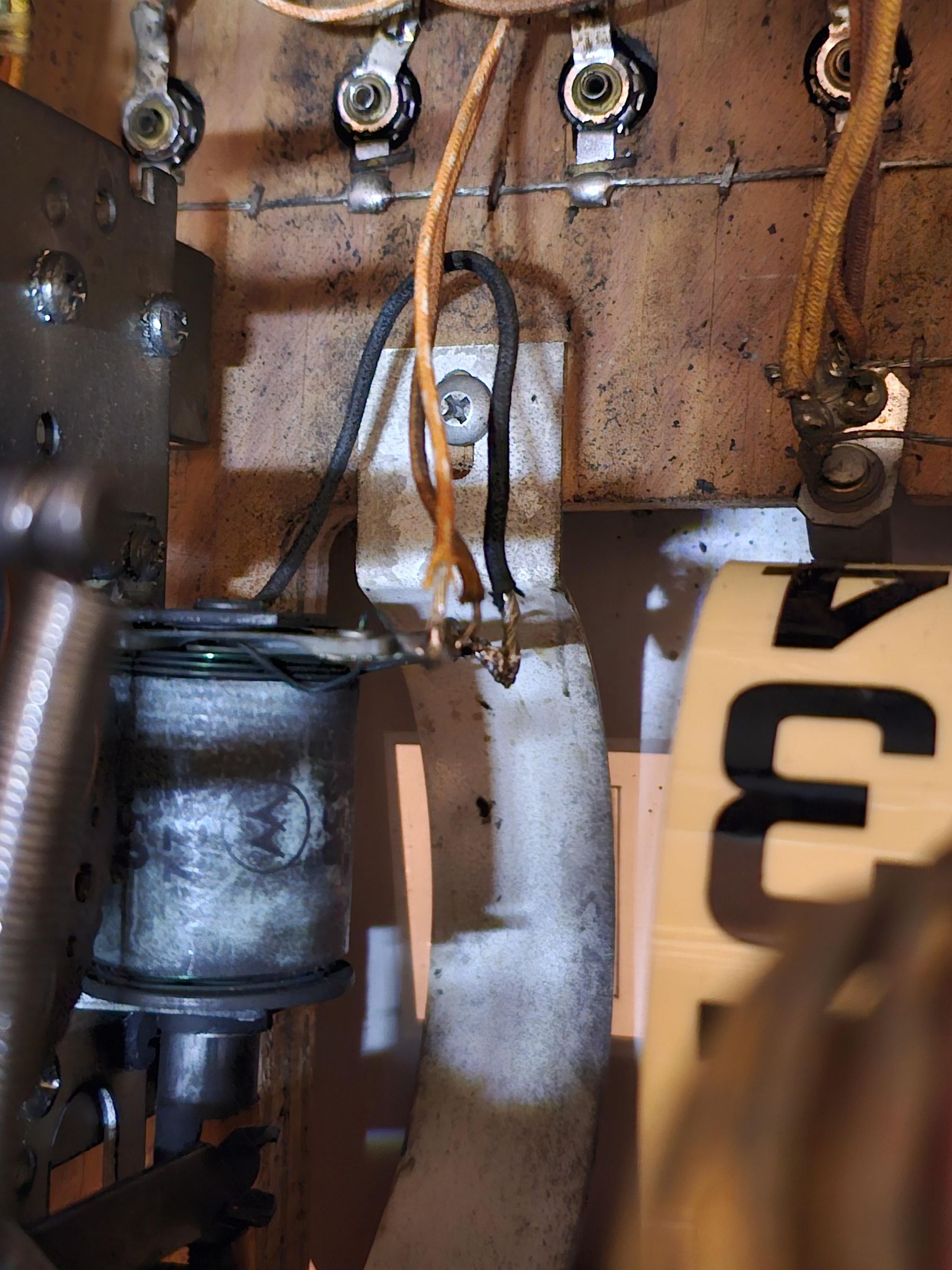
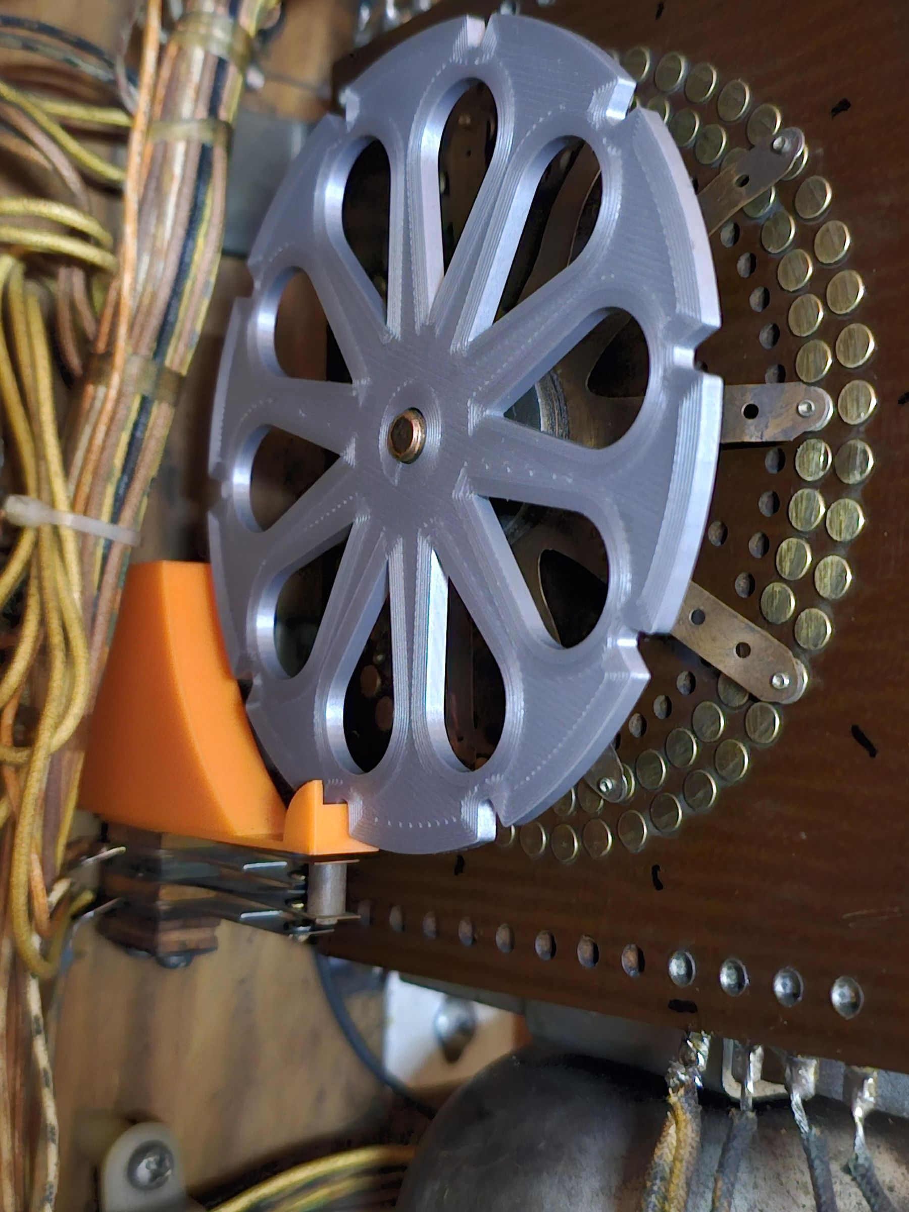
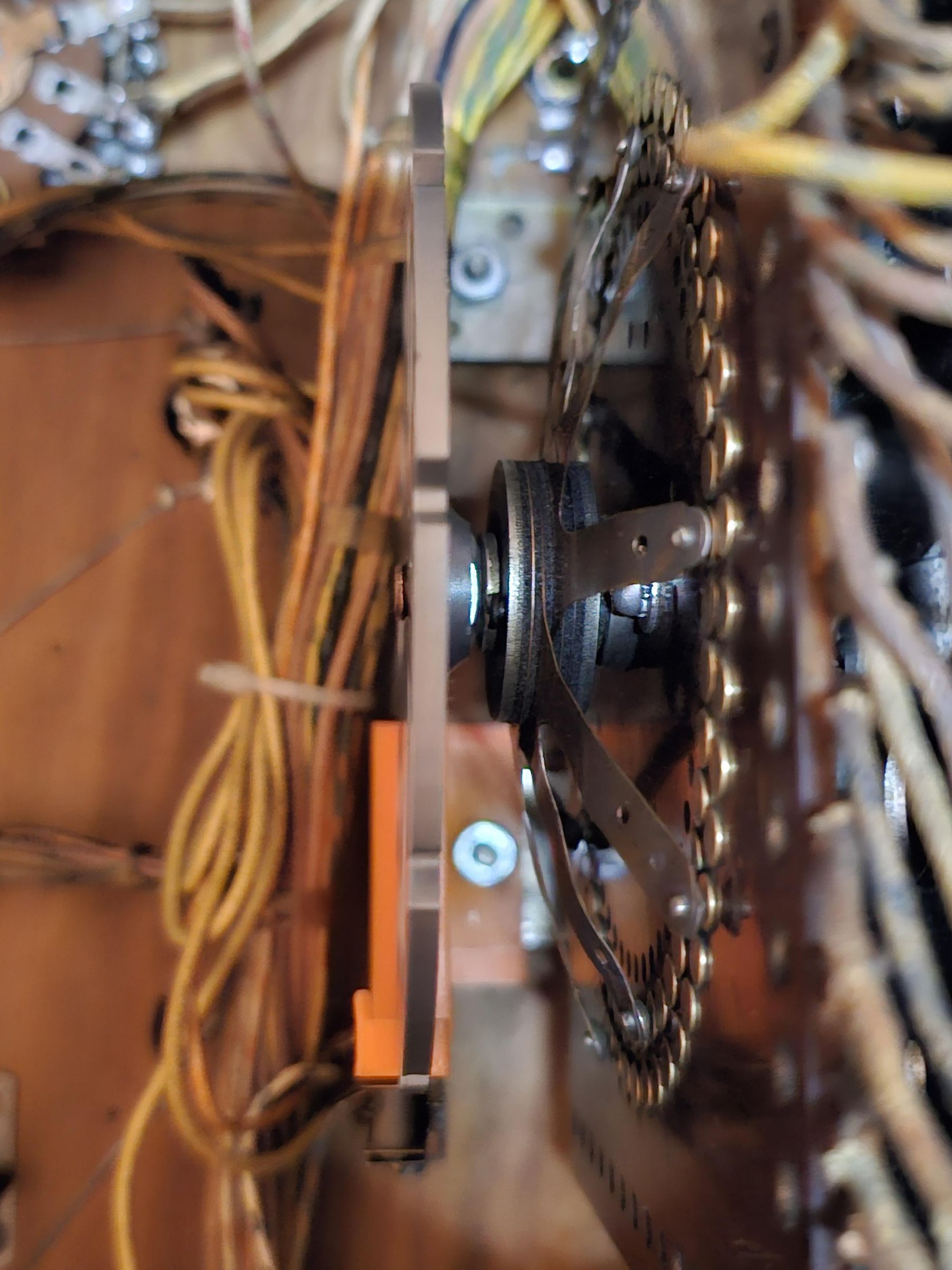
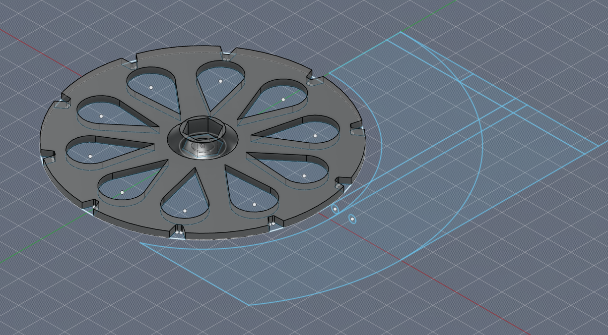
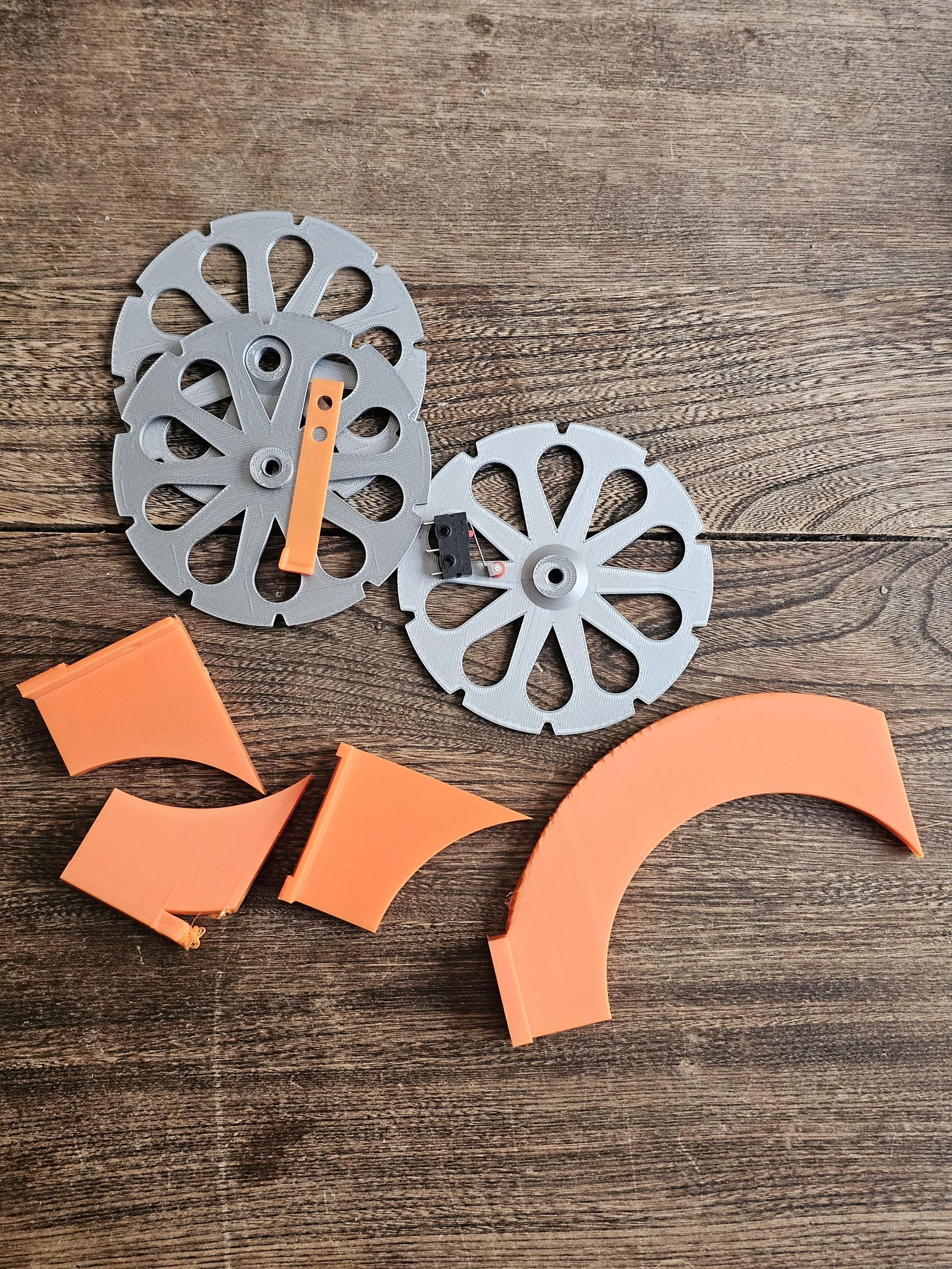
The model example here uses a normally open double switch stack.
Please download and print the 3D model files from:
https://makerworld.com/en/models/3020916-em-pinball-mechanical-cam-switch-mod#profileId-3394048
Feel free to give me a boost and a like if you enjoy mods like these.
For material, I would generally recommend ASA, ABS or PETG for pinball use, however I'm still using my PLA draft prints and they are just fine. With LEDs in the head, there is not a lot of excess heat. In the case of this circuit, the potential arcing of coil voltage is mainly going to be on the reset relay contacts.
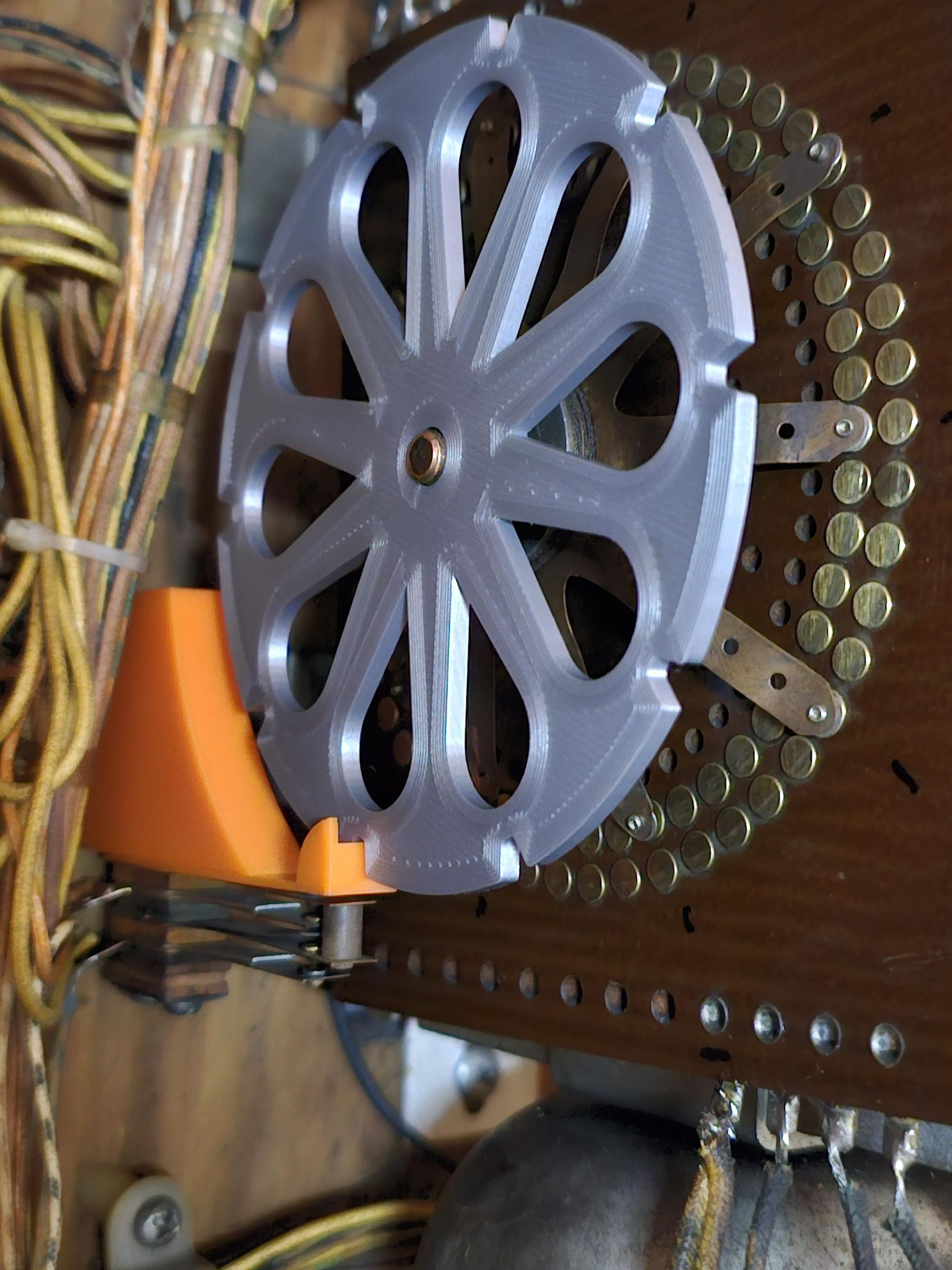
Once assembled, the wiring here is going to be the same as the score reel. We will piggy back the reset circuit from any of the score reel relay top switches as identified in Step 2. The second switch will then complete the circuit path from the reset relay leaf switches (yellow), to the orange wire on the match unit coil. As the reset relay actuates, if this switch is closed, it will then be able to pulse the match unit appropriately until the switch lever hits a divot where it becomes open.
To assemble this unit will hopefully be obvious from the photos. The actual disc should snap firmly around the existing nut on the mechanism. I recommend removing the nut so you may properly press this into the plastic printed cam. once in place, it should actually facilitate some more easy adjustments by hand tightening as needed.
The leaf is assembled with the divot part on the outside, and screws torqued into the housing. The housing should have fairly high tolerance in fitting over the original metal bracket, and use the existing nut here to secure it in place. Provide enough torque and play such that the unit sits firmly and you may manually pulse the no. match coil forward, and observe the cam rotation smoothly over the disc. Once in place, make manual turns to line it up with the outer leaf fingers and the notch, so that with ever 5 steps, the sequence of the hole is where you want it.
Wrapping Up What Did I Forget?
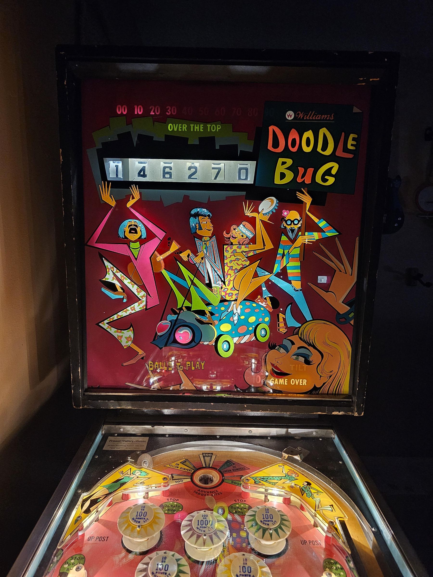
The game should be pretty playable now, but what's missing?
Oh yeah, the high score replays! totally messed up from our mod.
Good news, we have even more configuration now!
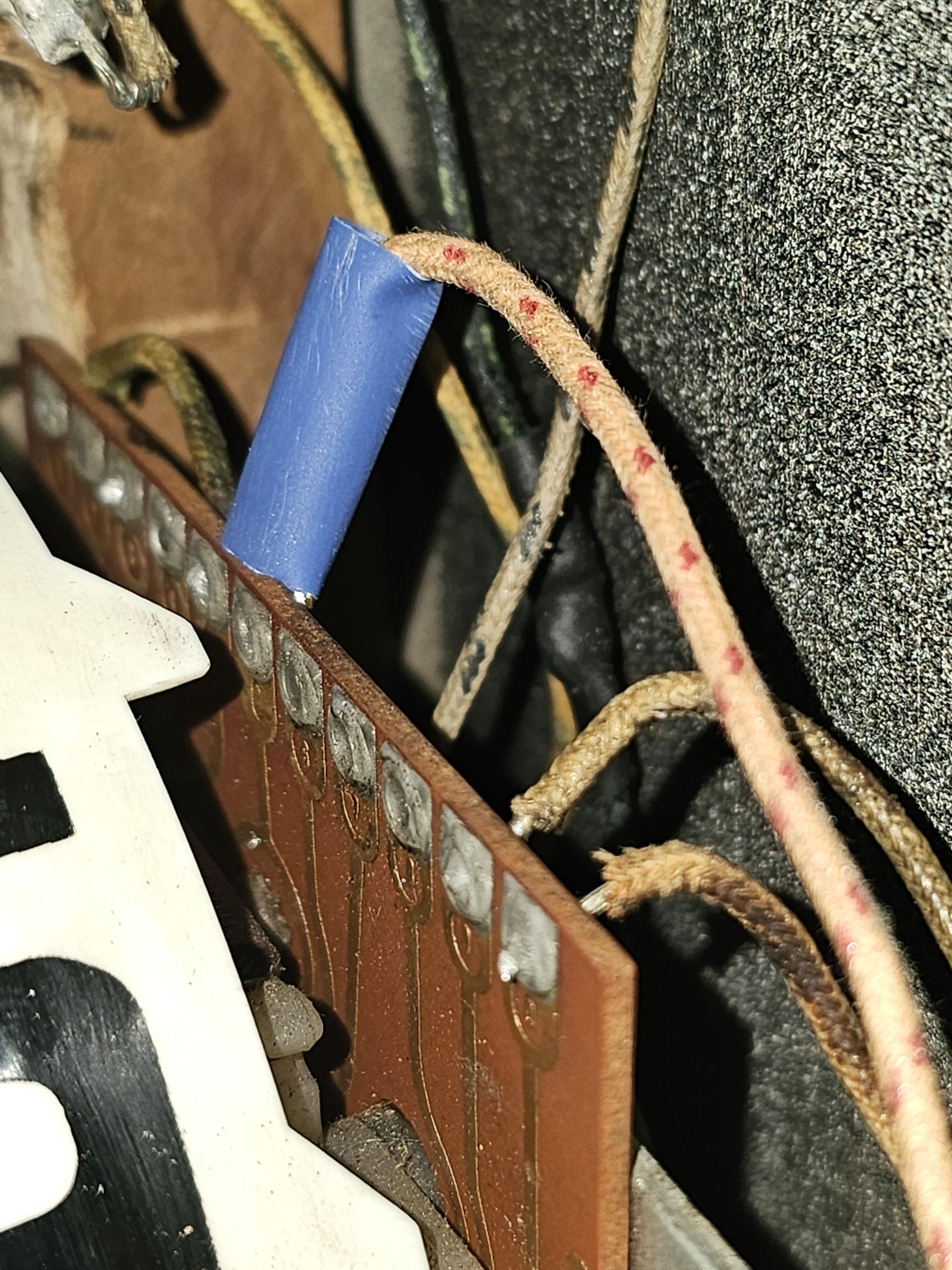
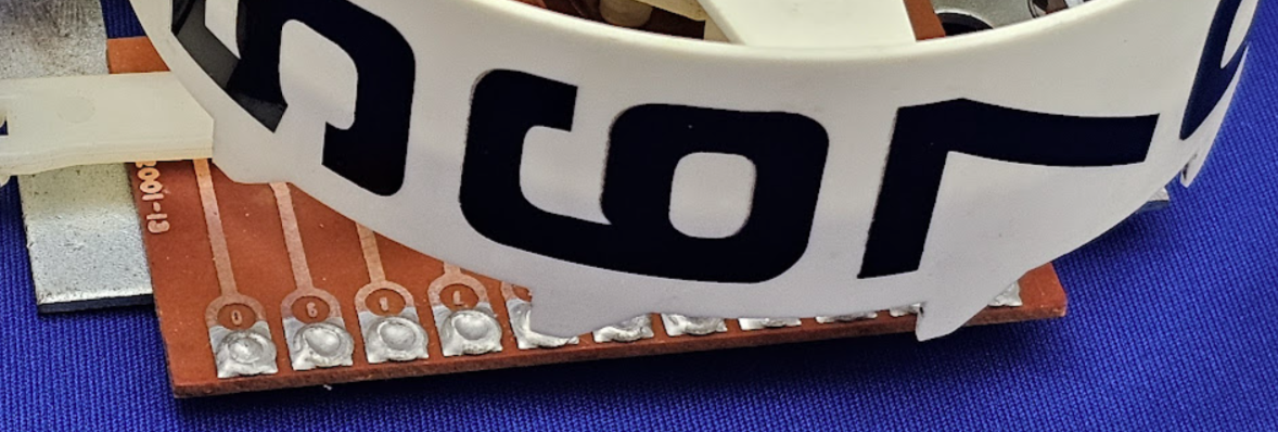
At the top of your score reel mech (assuming you have the recommended type with circuit board), you should find 11 solder points. These will be labeled 1,2,3,4,5,C,6,7,8,9,0
As you step through the reel, each digit will complete a circuit with the C (common) point.
Now look at our existing replay logic, (these are essentially all direct connections to the 10k reel top) based on the grey wire (and should still function), the red lead however relies on the 100k relay actuated via the transfer relay. BUT WE WANT our 170k score card to make sense?
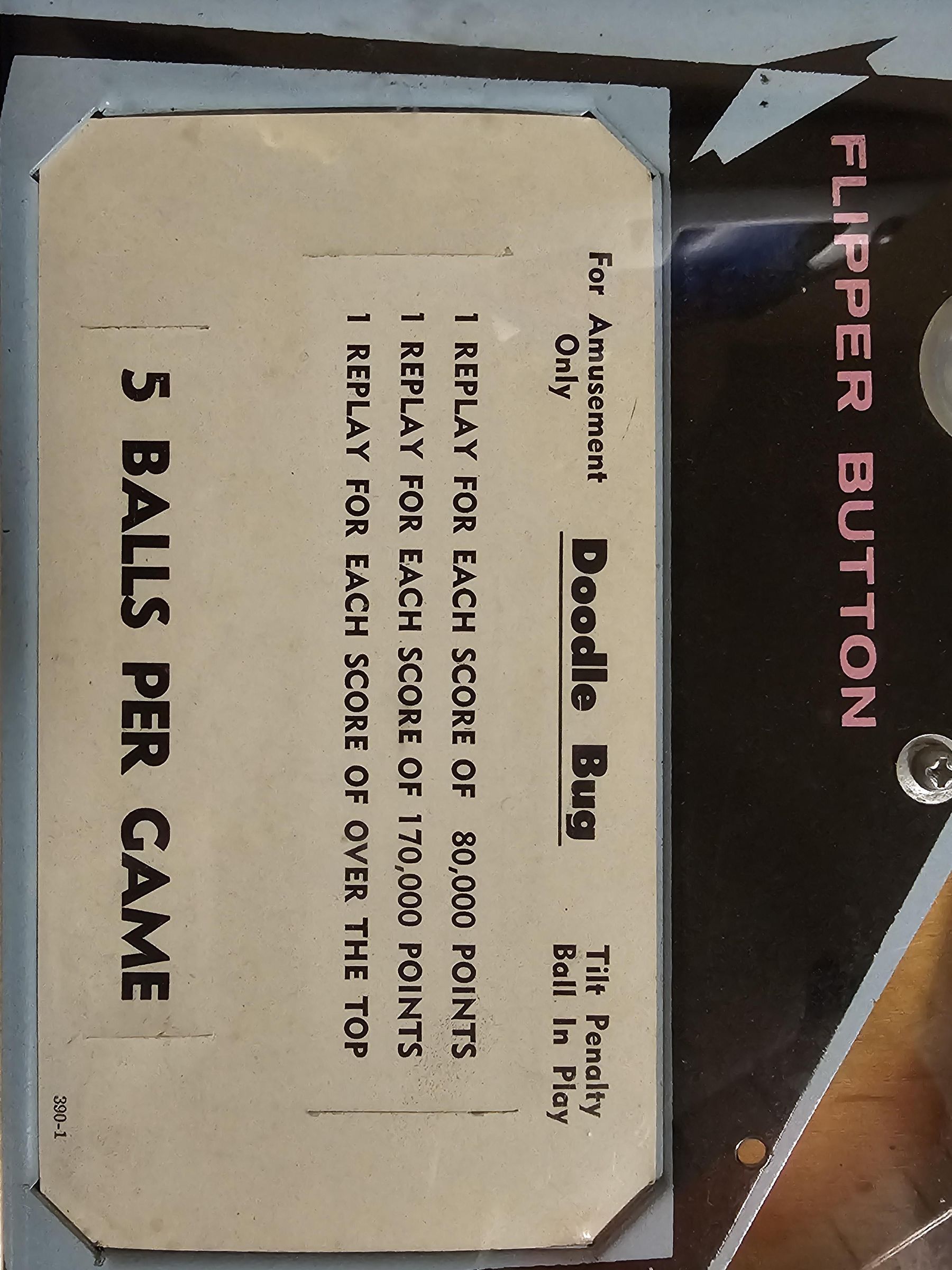
Ok, we just need to extend this circuit from our own jones plugs completing the circuit with our new relay. In this case, we will want to use the 1 that can route back to the C on our 100k reel which will then connect to the same match location as the grey lead (black on white lead that connects to the normally closed 100k relay and then on to the credit unit), and plug this into the 70k slot to configure 170k.
Then for over the top scoring, we'll connect another jones plug lead to the 9s of our 100k reel and to the (over the top) plug on the replay selection.
Hopefully the logic here is repeatable for whatever configuration you would like. In my case, I also chose to replace the grey lead with a 100k reel from the 0 location. The reason is that without this, we would be scoring a replay at every 10k interval of that connection (but maybe that's what you want, you do you!).