How to Repair a Broken Wind Sensor in a Nylex Digital Weather Station Plus
by redbackspider77 in Workshop > Repair
12 Views, 1 Favorites, 0 Comments
How to Repair a Broken Wind Sensor in a Nylex Digital Weather Station Plus
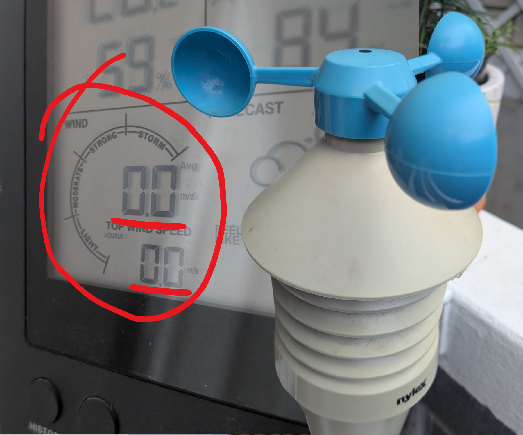
The wind measurement for my Nylex Digital Weather Station Plus refused to work only about a year after purchase, zeroing out on the display. I knew this piece of technology still had plenty of potential, as the temperature and humidity still worked well. Upon looking in the reviews at Bunnings, I found that this was a common failure point in these cheaper weather stations, and was worth dissecting.
Supplies
In my scenario, I required:
- Screwdriver with a PH2 and PH0 bit
- Soldering iron, wire and flux pen (one of my first soldering projects, but I used a 99.3% tin, 0.7% copper alloy)
- Conformal coating/hot glue gun
- Multimeter
- Electrical tape
- Wire stripper/pliers
- Utility knife
- Hand drill
- Sacrifical wire (I used a jumper wire that I had on hand)
- Pure acetone (to dissolve conformal coating, IPA may work too)
- Small red LED (∅3mm to be precise) — if you find that the indicative light has corroded and want to fix it, optional (see the end of step 1)
Take Apart Enclosure
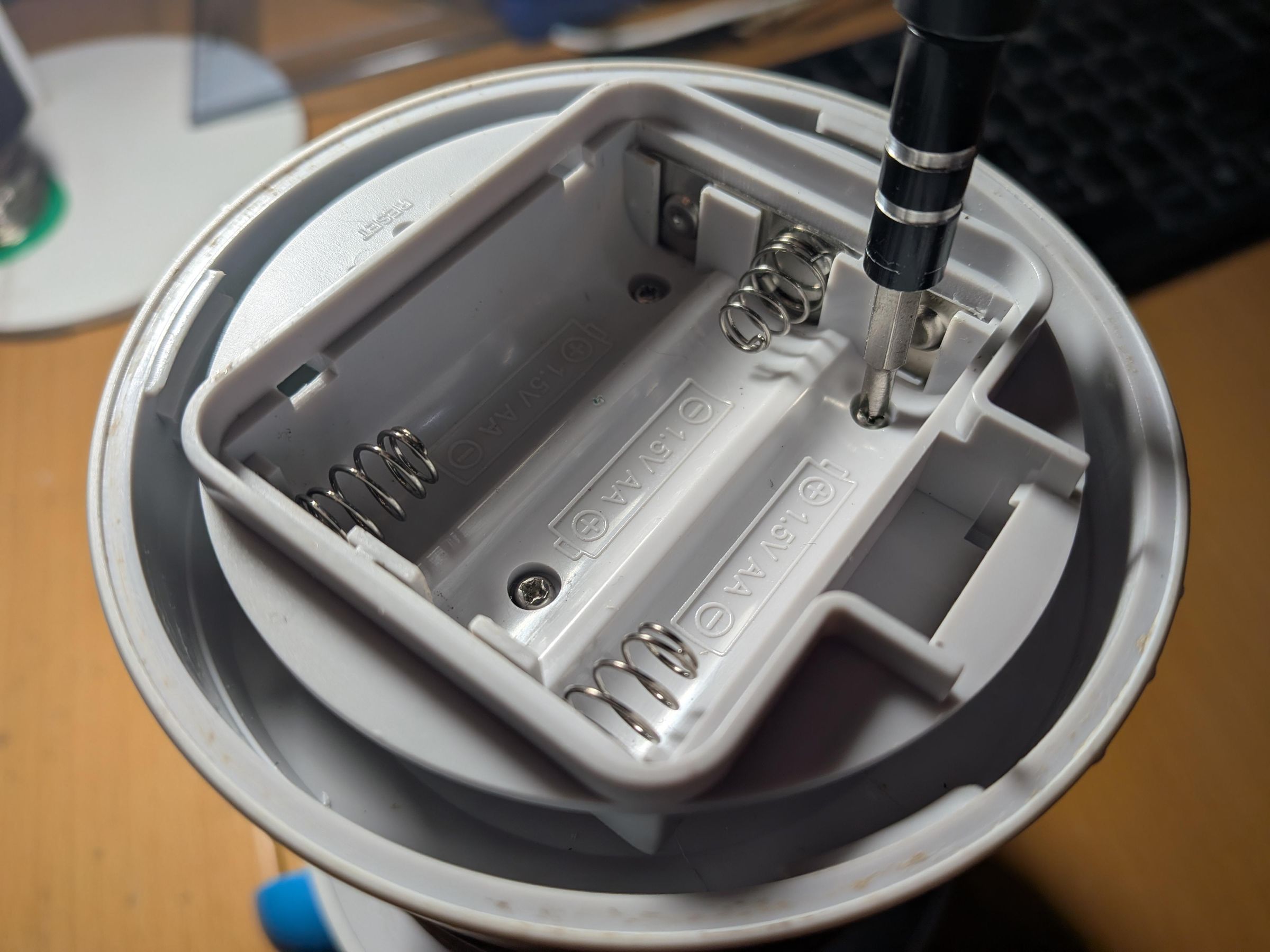
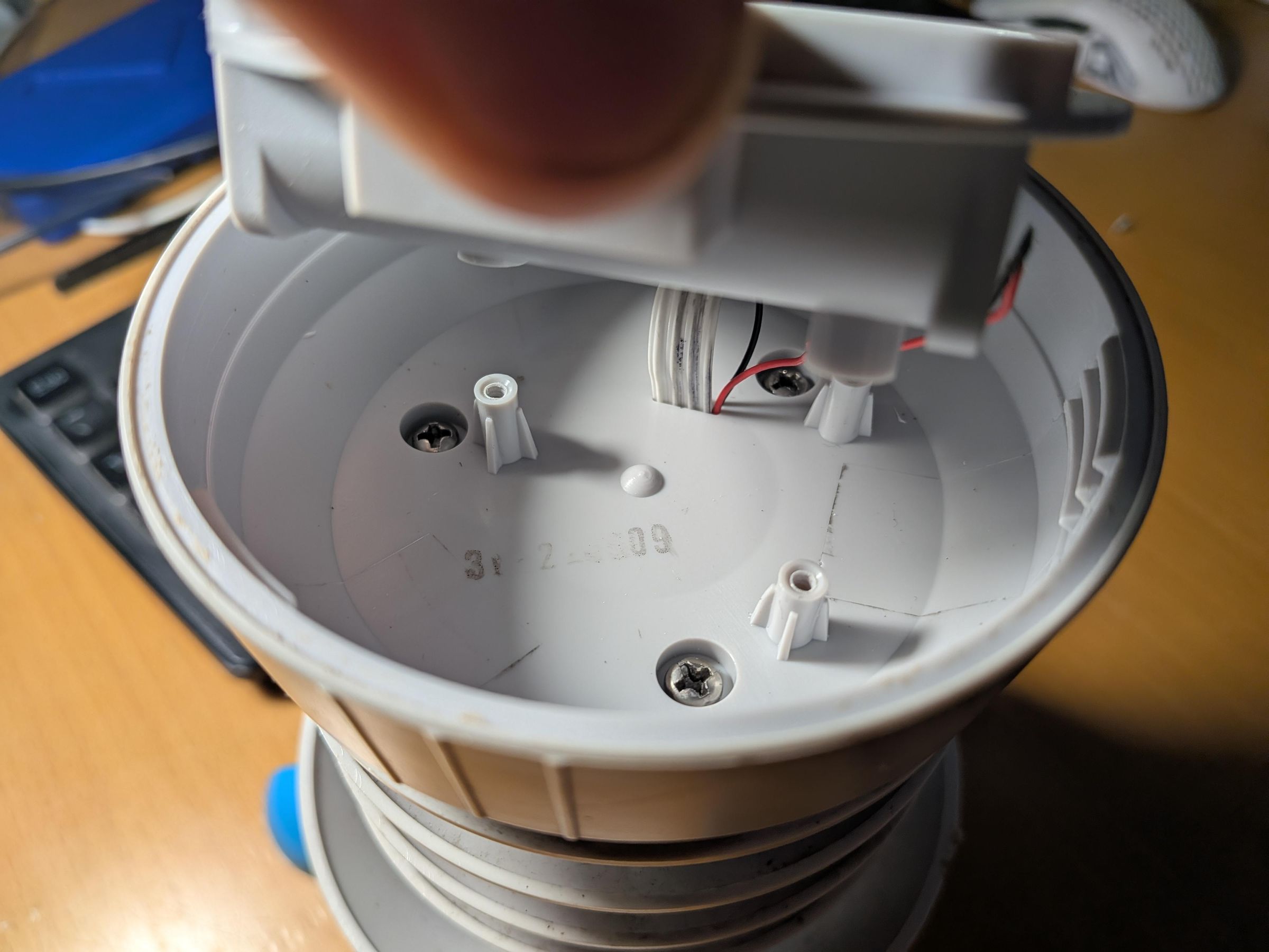
Remove batteries to expose 3 screws. Unscrew these to reveal another 3 larger screws that hold the weather station together. In hindsight, I recommend desoldering the power, ground and reset wires at this stage to make the rest of the repair easier.
You will then be able to open the housing for the main electronics, which you need to unscrew from the top. At this point, you should have three parts — the ribbed sides of the weather station, the top with the cups for measuring wind and the main electronics in a plastic compartment.
Note: here, you will be able to see if the red LED has corroded — the legs were completely rusted in my scenario.
Removing Wind Sensor
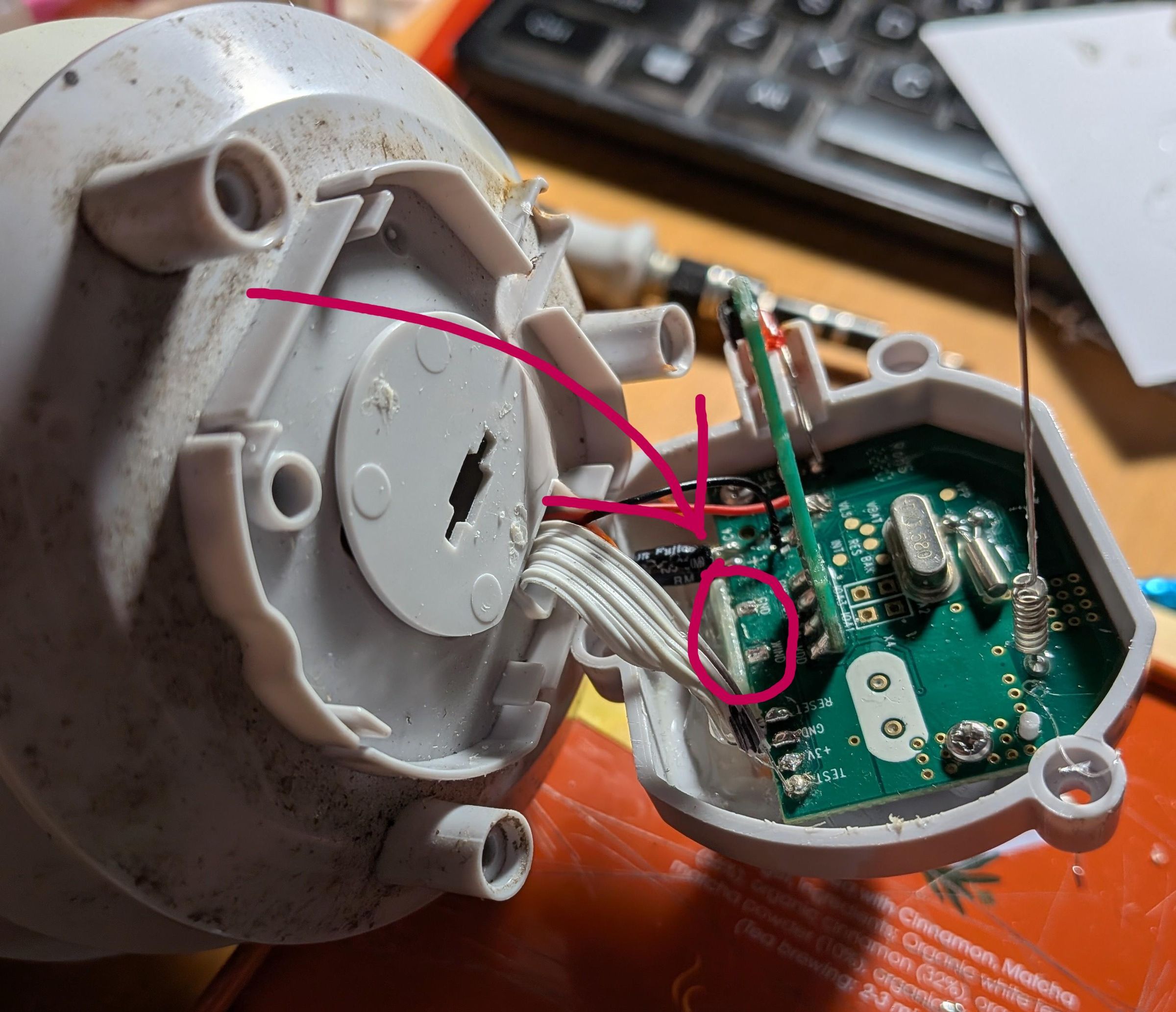
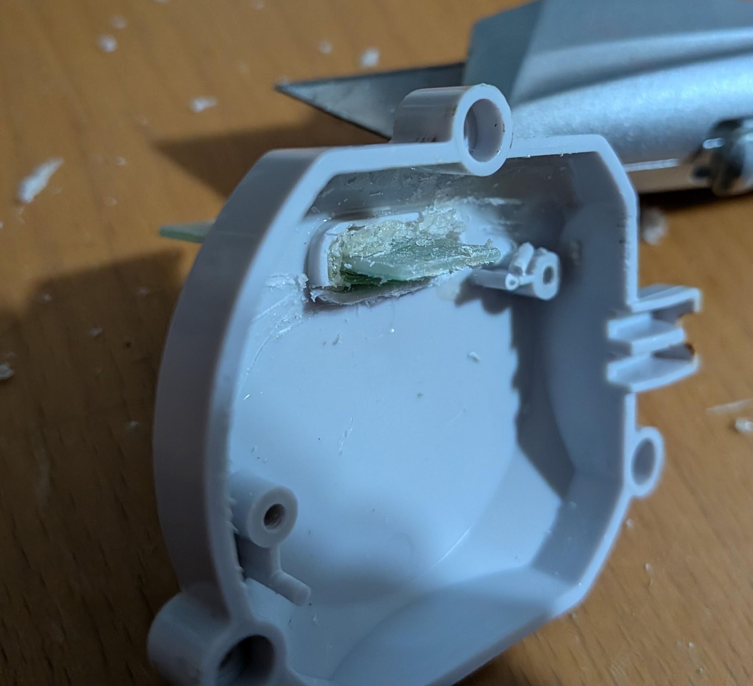
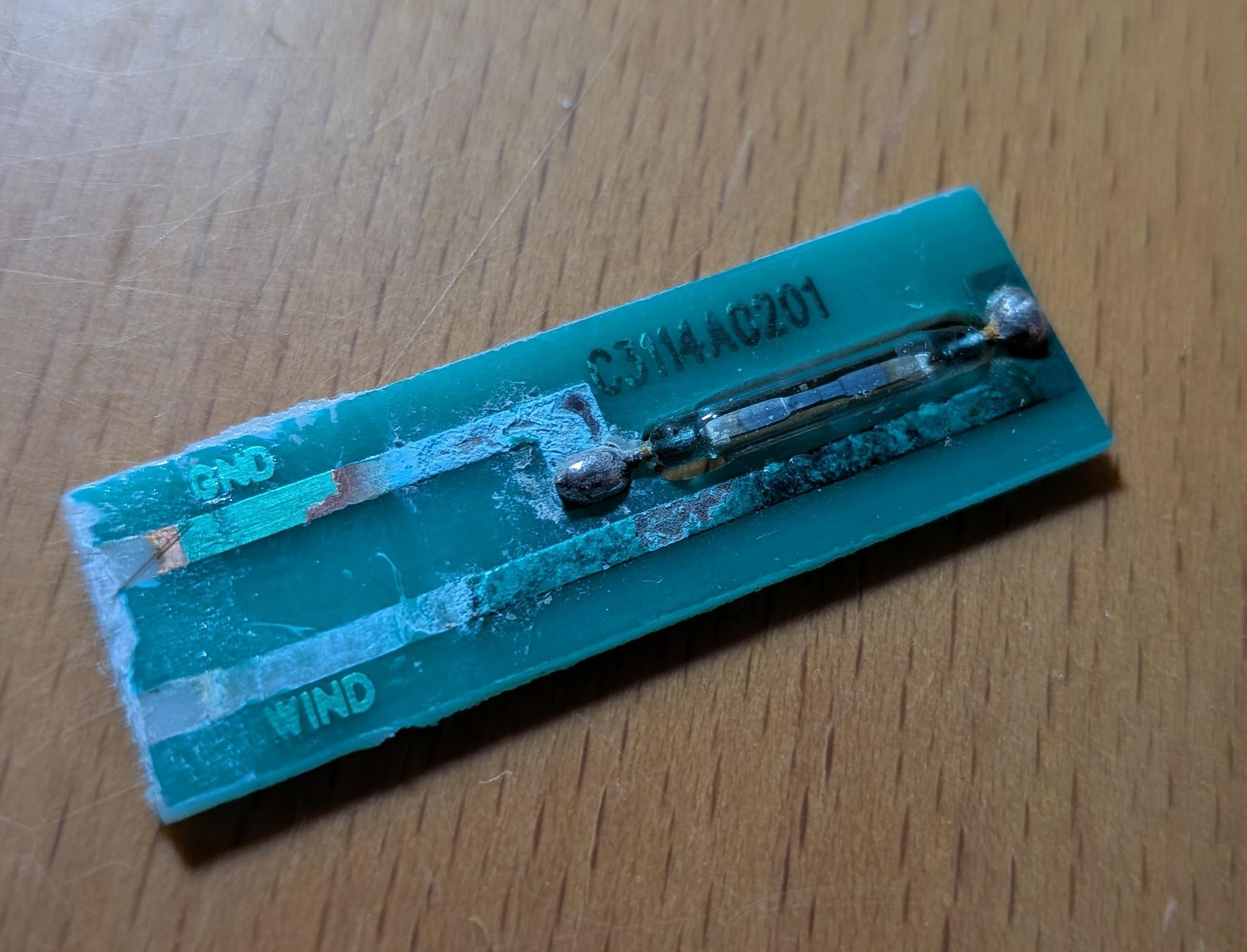
Nylex uses some sort of acrylic conformal coating to protect its inner electronics from the elements. To desolder and access the wind sensor, this must be removed. Brush on some acetone using a cotton swab on the Wind and Gnd points (see image), as well as the joints for the LED if you want to replace it too. Using a wooden pick, you should now be able to scrape away the coating.
Once most of it has been removed, desolder the joints, and unscrew the board from the plastic body. This will leave you with the wind sensor PCB embedded in another form of plastic adhesive, which can be softened using acetone and carefully (as in not to cut yourself like I did, you can scratch the PCB as much as you like at this stage) scraped out using a utility knife.
You will now be able to wiggle out the wind sensor. Upon inspection, this is actually a reed switch that closes when a magnetic field comes near it — every time the magnet in the bearing of the wind cups passes this component, current flows to indicate one rotation to the computer. This way, it is able to calculate speed of rotation, and wind speed from there. The problem with this design however, is that the PCB is exposed to moisture, and the copper traces corrode over time, destroying the connection.
Reed Switch Bypass Surgery
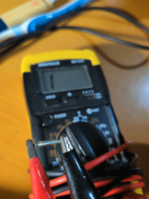
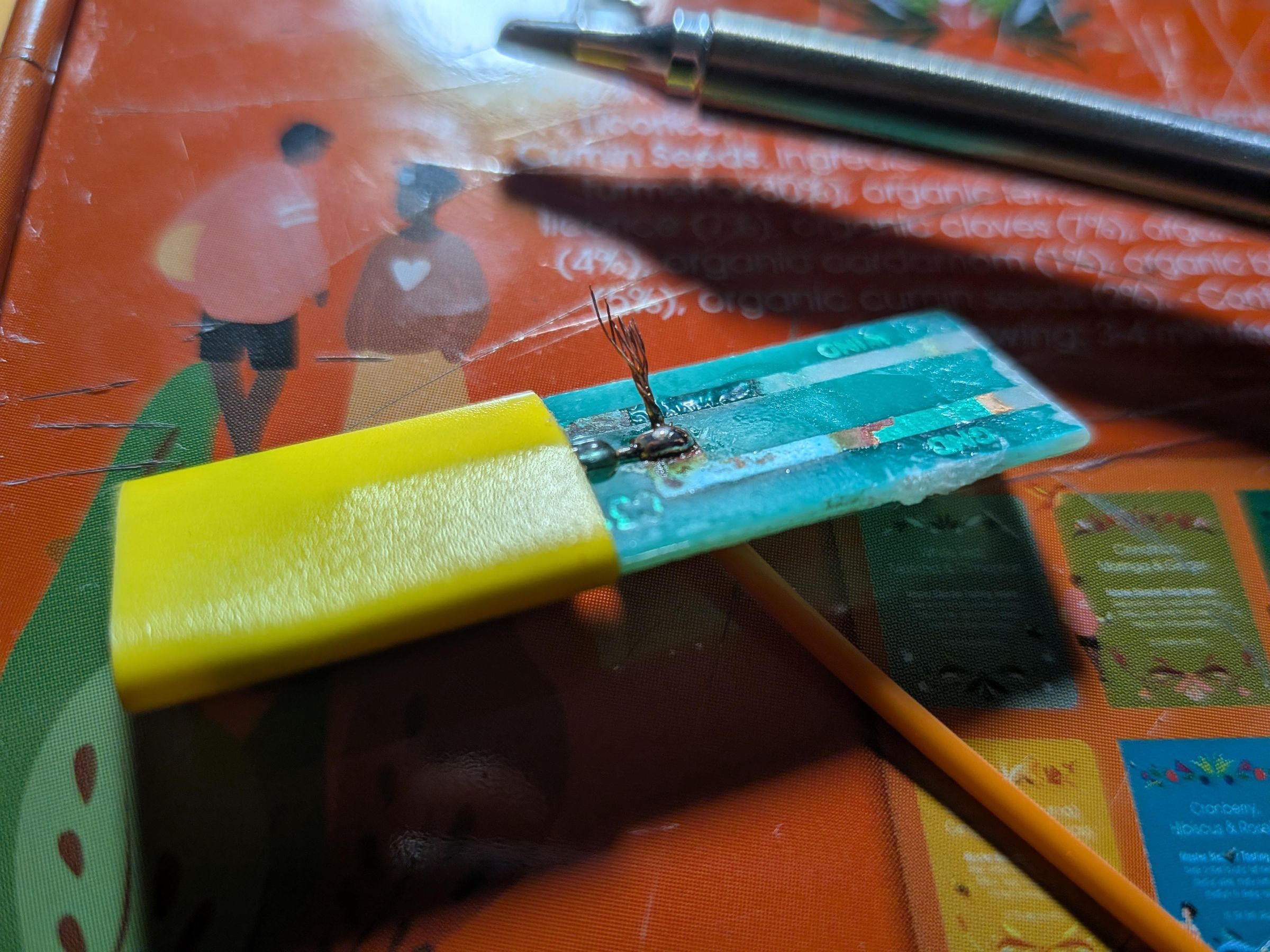
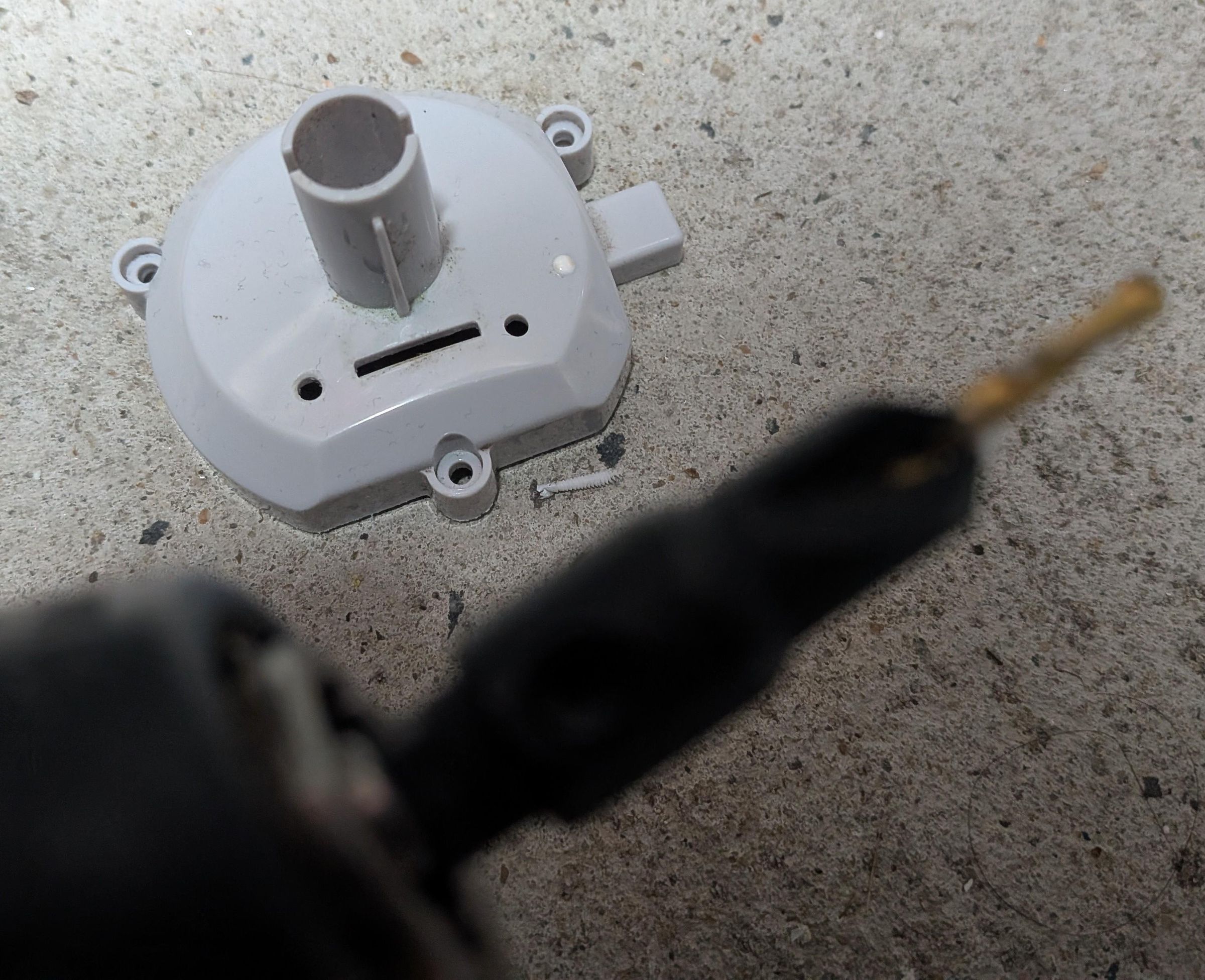
First, desolder the old connections to extract the reed switch. Using a multimeter set to continuity mode, move a magnet over the reed switch to test whether it still works. If it does not, you will need to buy a new one (make sure the glass ampule is 14mm long, e.g.). In my case, the reed switch still worked great:
Since the PCB is futile, I decided the best way to fix this would be to solder wires that do the job of these copper traces. To do this, thread one wire at a time, and hold the reed switch in place with some electrical tape (make sure the orientation is the same to be safe, not sure if this causes noticeable change in accuracy). Important: make the top connection as slim as possible so that the PCB still fits in its slot.
Next, drill two holes in the plastic body for the electronics to allow the wires to pass through. Slide the PCB and wire into the plastic body again, and secure everything in place using hot glue. Make sure the PCB is at the right height, and the wires fit when you slide the plastic body back into the top of the weather station — I did this during the hot glue process.
Putting Everything Back Together
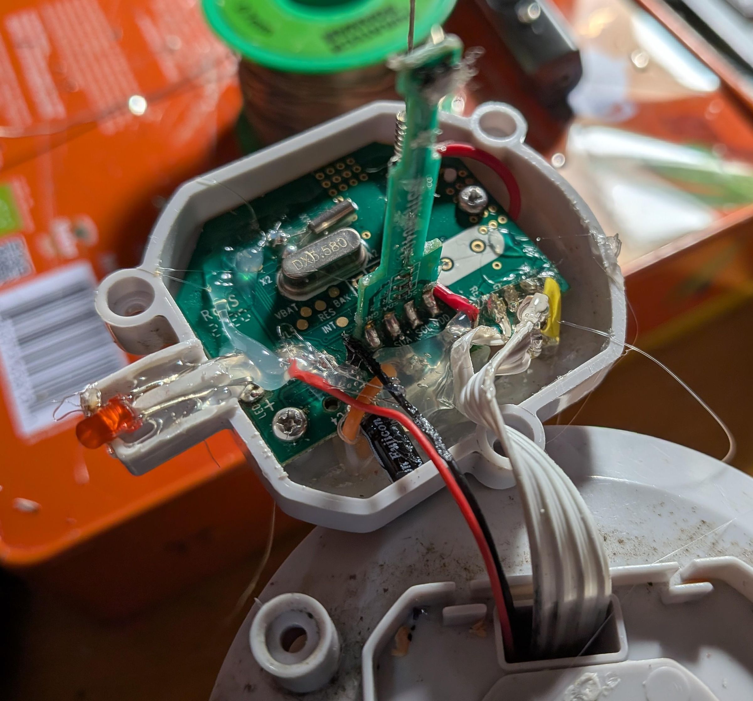
You may have excess wire from the reed switch, so trim it before screwing the main electronics board back on the plastic body. Then, solder these wires to the Wind and Gnd pins on the board. You may also replace the LED at this stage. I recommend testing your soldering using continuity mode at Wind and Gnd again, and swiping a magnet over the reed switch.
Now, spray the board and your newly soldered joints in conformal coating, or encapsulate the whole thing in hot glue like I did (though this will make it less repairable in the future ;). I recommend adding some hot glue to the legs of the LED nevertheless, to prevent corrosion there. Once it mostly dries, you can now screw everything back together in reverse order, and solder Power, Gnd and Reset back together at the battery holder. Next, throw in some batteries and give the wind cups a spin to test if it works again.
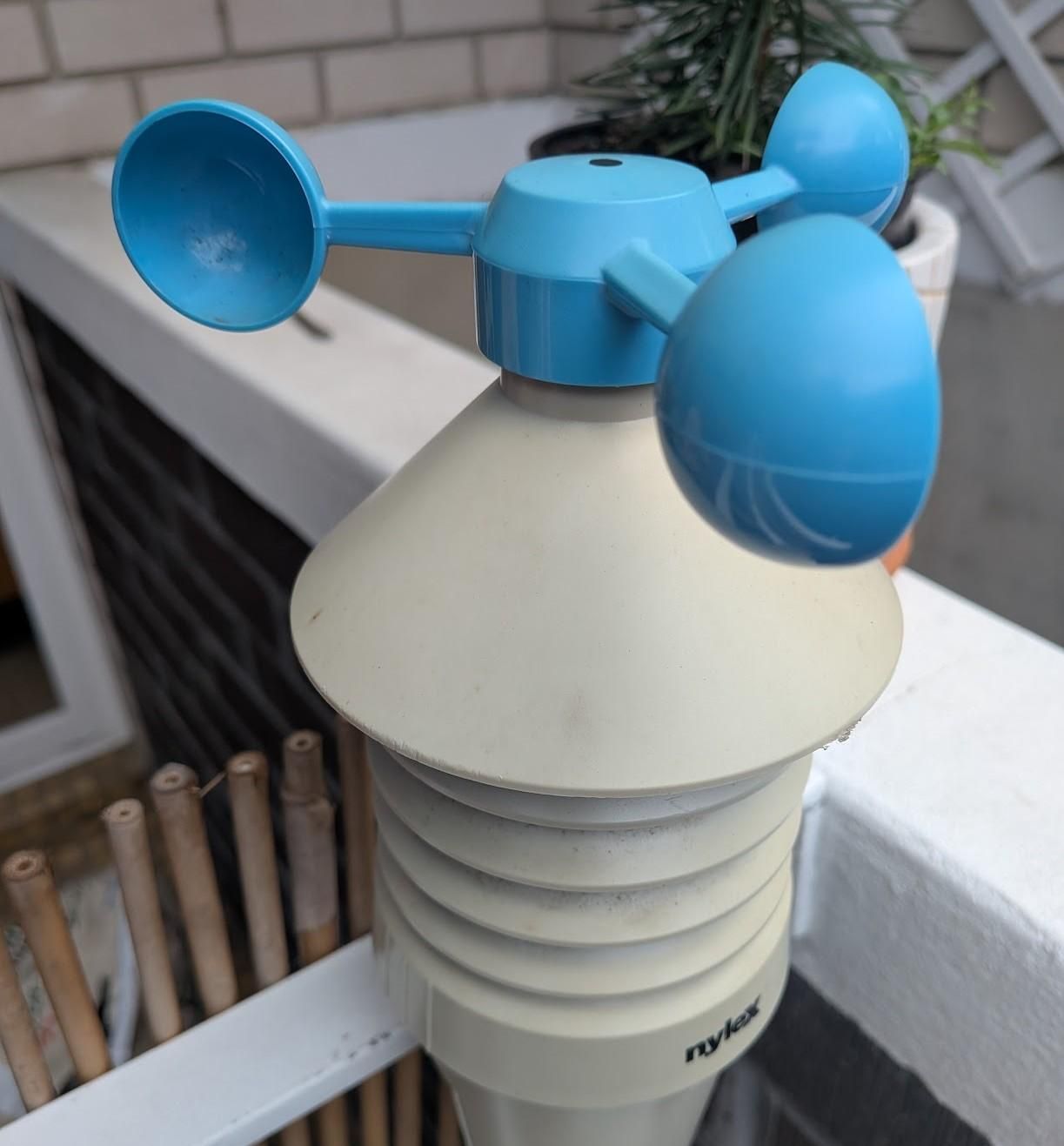
Congrats, you can now see how windy it is outside, you may have a blinking LED and you learnt what a reed switch is.