How to Rotate Mounting Holes of Heavy Duty & High Load Actuators
by Progressive Automations in Workshop > Repair
115 Views, 0 Favorites, 0 Comments
How to Rotate Mounting Holes of Heavy Duty & High Load Actuators

In some electric actuator installations, the position of the motor housing, cable exit, or mounting holes can affect how easily the actuator fits into a project. This is especially common in compact assemblies where side-mounted motors or cables may interfere with surrounding frames, brackets, or enclosure walls. In some cases, we can customize actuators with rotated mounting holes before shipment; however, custom manufacturing fees may apply, and lead times can take up to 13 weeks. If your project requires a stock heavy-duty or high-load actuator and you are comfortable making this adjustment yourself, this step-by-step article explains how mounting holes may be rotated on select models.
Supplies
-DC Power Supply (Must output actuator's voltage)
-Vice
-Heat Gun (Optional but helpful)
-Heavy Duty Screwdriver (or at least a 16” lever arm)
-Torx Screwdrivers Set
-Heavy Duty Adjustable Wrench
-Needle Nose Pliers
-Impact Driver with Power Nut Driver Bit
-Allen Keys
Defining Your Model
Front Shaft Extension
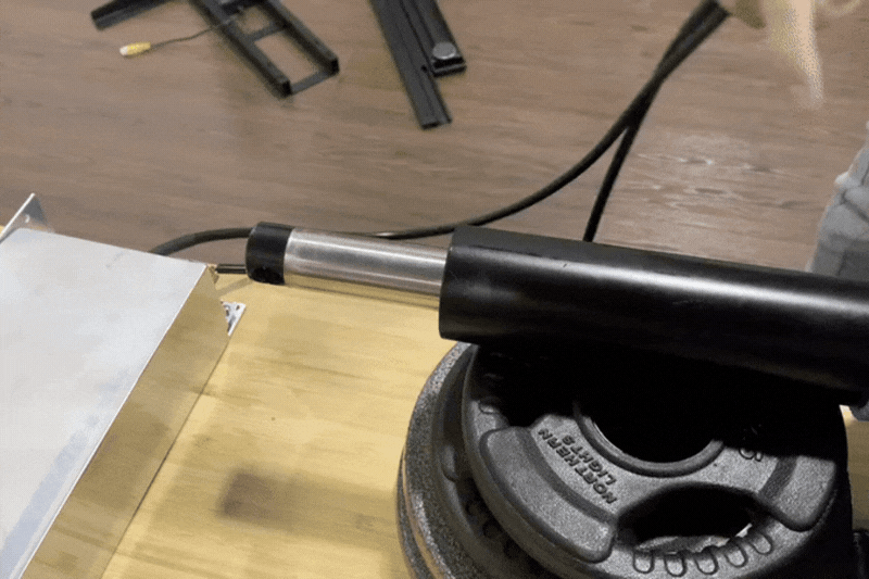
We will begin with the front mounting hole rotation. Supply the appropriate voltage (see actuator’s sticker/label) to the actuator’s motor leads and extend the stroke enough to place the stainless-steel shaft into a vice.
Securing Into a Vice
Using a piece of leather or something similar to protect the shaft from the vice plates, clamp the shaft with just enough pressure to prevent it from slipping during the following steps. Do not overtighten this vice, as too much pressure may crush the stroke rod.
Note: The stroke rod end and motor end nut will require at least a 16” lever arm to apply enough torque to rotate.
Heat Up the Front Mounting Point
Use a heat gun briefly to heat up the entire area of the front mounting point to reduce the torque required when rotating.
Rotational Torque
With the user closest to the shaft rod side, rotate the front mounting end’s rod fixture piece 90° counterclockwise to complete the rotation. Rotation complete.
Warning: Do not rotate mounting holes counterclockwise more than 1 turn.
Rear Mounting Hole Rotation of PA-13
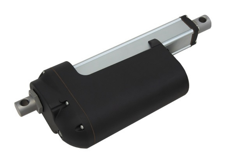
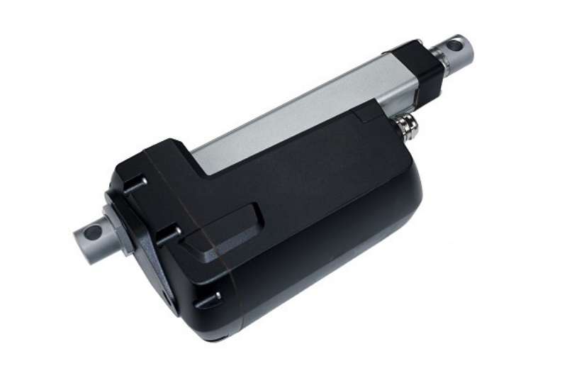
This PA-13 video illustrates how to rotate the mounting holes of a PA-13. An older model is being used as an example; however, the procedures are very similar for both new and older model actuators. The major difference is the visual appearance from the exterior of the newer and older model PA-13s. Our older PA-13 model has rounded edges for the motor housing, while the newer PA-13 model has squared edges.
Large Torx Screw & Nut Removal
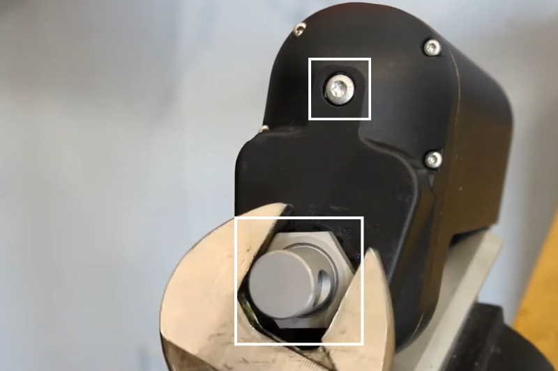
Remove the large nut that holds the mounting component as well as the large Torx screw.
Back Mounting Plate & Torx Screws Removal
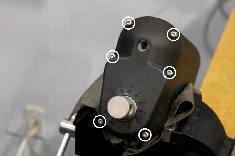
Now, loosen all six Torx screws located at the back of the mounting plate and then remove the back mounting plate.
Back Casing Removal
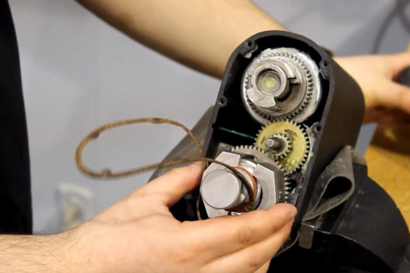
Slowly remove the back casing to prevent damaging the gasket.
Mounting Piece & Internal Component Removal
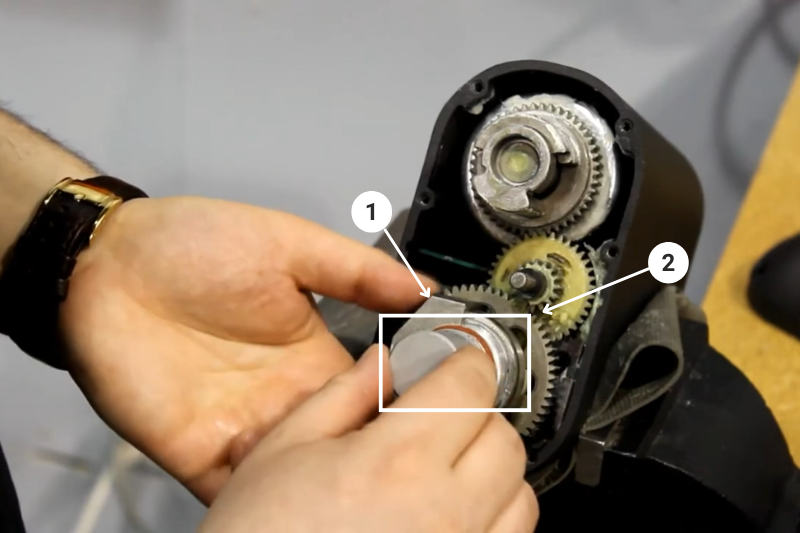
Remove the metal component that’s holding the mounting piece, then remove the mounting piece from the actuator.
Spring Removal
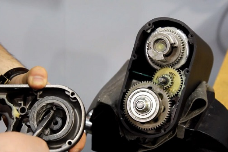
Remove the spring with a pair of pliers. Make sure not to pull too hard and deform the spring.
Spring Placement
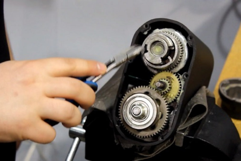
Next, take out the spring, place the spring as shown.
Position Your Mounting Piece
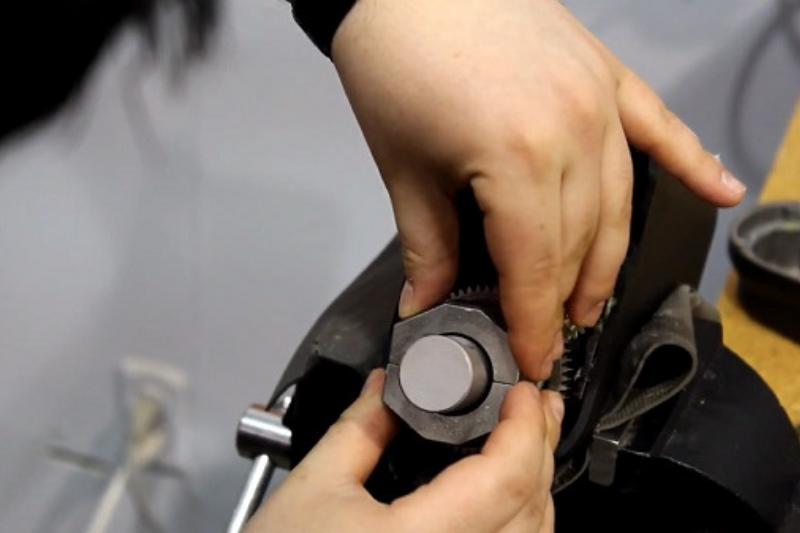
Position the mounting piece at the angle that you like. Then place two halves of metal pieces back on to the mounting piece.
Gasket Placement
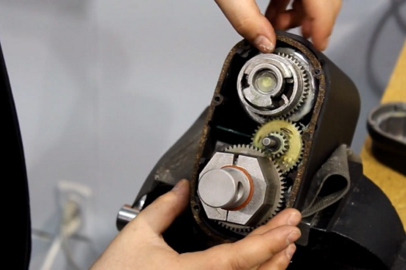
Put the gasket back in its original place and then put the mounting plate on.
Securing the Mounting Nut & Screws
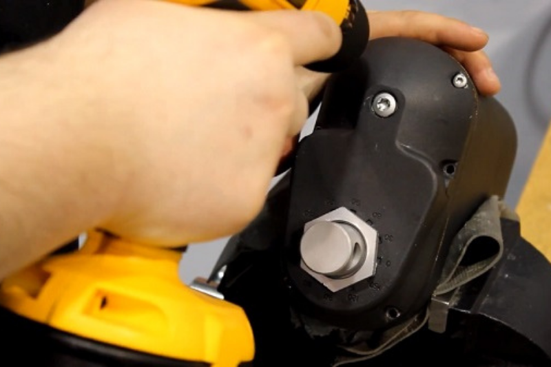
Add all the screws back in as well as the mounting nut.
The PA-13 Stroke Rod End Attachment has the following thread specifications:
- Thread Size: M27
- Thread Pitch: 1.0 mm
- Thread Length: 11.0 mm
- Thread Tolerance: 6h (within 0.15 mm)
If you have any further questions on the PA-13 rear mounting holes rotation, please check the link below for the video:
Rear Mounting Hole Rotation of PA-17 (24" Stroke or Shorter)
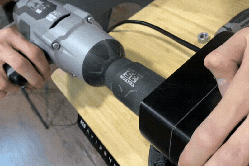
Loosen and remove the large nut attached to the mounting point using a wrench or an Impact Driver with Power Nut Driver Bit.
Disengage the Locking Teeth and Rotate 90°
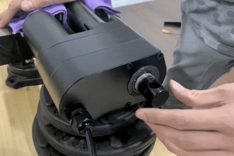
Push in on the mount enough to disengage internal locking teeth and then rotate 90°.
Retighten the Large Nut
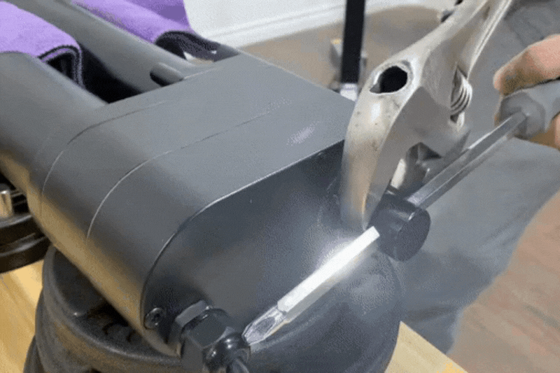
Retighten the large nut and torque to a similar pressure that was needed to first loosen it to complete the rotation.
Rear Mounting Hole Rotation of PA-17 (stroke Above 24")
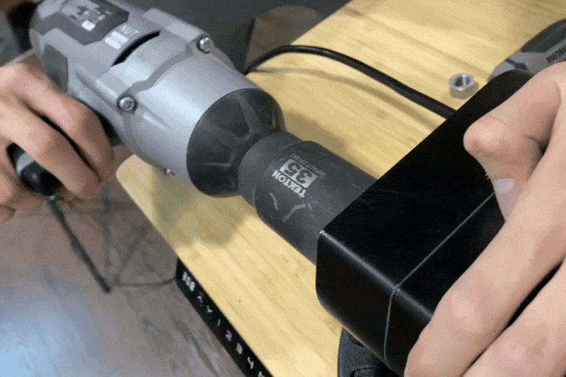
Loosen and remove the large nut attached to the mounting point using a wrench or an Impact Driver with Power Nut Driver Bit.
Hex Cap Screws Removal
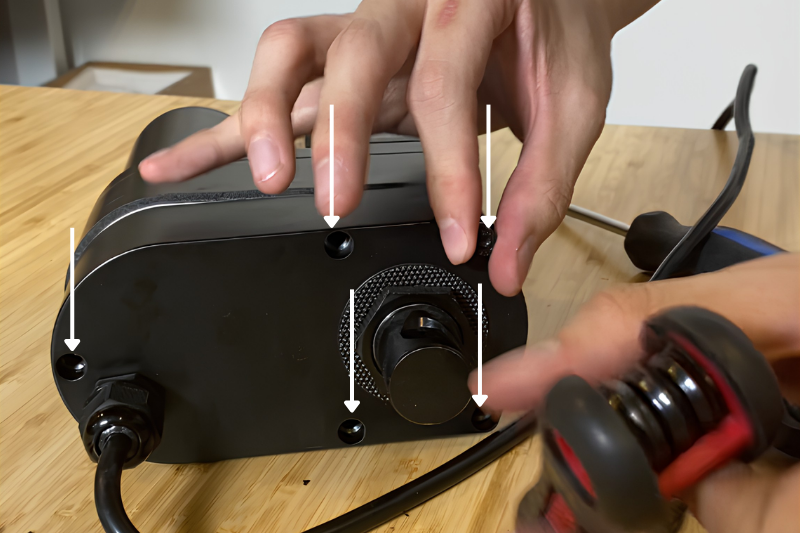
Remove the 5 hex cap screws with Allen keys so the bottom case of the actuator can be removed. The shortest hex cap screw is located closest to the power cable.
Moving the Cap Down
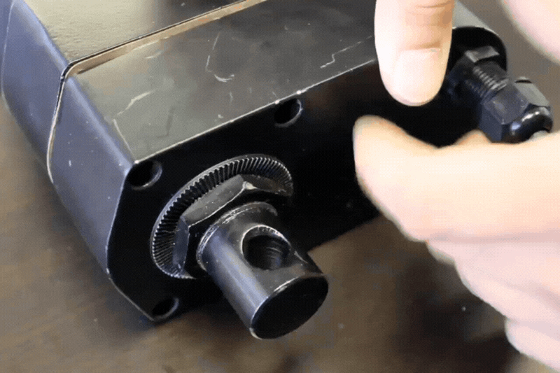
Loosen the power cable lock screw and move the cap down so the bottom case can be slid down along the power cable.
Slide the Bottom Case Down
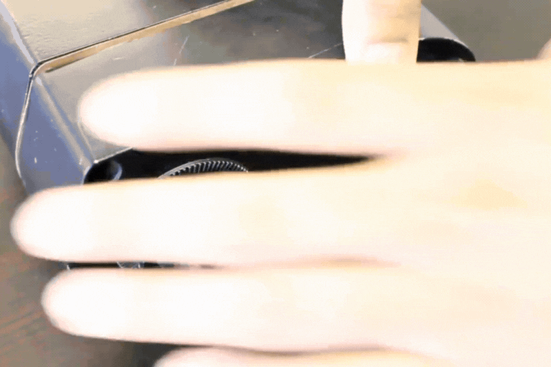
Slide the bottom case of the actuator down the cable and expose the intermediate gear and motor mount assembly.
Loosen the Large Nut
Loosen the large nut holding the motor mount in place to rotate the motor mount counterclockwise 90°.
Note: Placing in a vice can help loosen and remove the nut
Retighten the Large Nut
Retighten the large nut and torque to a similar pressure that was needed to first loosen.
Reassembling the Actuator
Reverse the last six steps to reassemble the actuator. Rotation complete.
Rear Mounting Hole Rotation of PA-HD1 and PA-HD2
All PA-HD1 & PA-HD2 actuator variants follow a very similar procedure used for PA-17 (24" or shorter stroke).
Rear Mounting Hole Rotation of PA-HD3
All PA-HD3 actuator variants follow a very similar procedure used for PA-17 (stroke longer than 24"), with the only difference being that there are 6 screws instead of 5 screws holding the bottom base cover in place.
IN SUMMARY
To summarize, many actuators may need their mounting holes rotated for certain installation conditions and space requirements. By using a few tools and spending some time to follow our step-by-step guides, you too can rotate the mounting holes of an actuator to the required positions.
If you have any queries or wish to discuss our products further, please do not hesitate to reach out to us! We are experts in what we do and will be happy to assist in any way we can.
sales@progressiveautomations.com | 1-800-676-6123