How to Build a Nintendo Arcade
by russm313 in Circuits > Electronics
367267 Views, 1263 Favorites, 0 Comments
How to Build a Nintendo Arcade
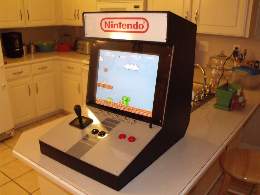
This Instructable will show you how I built my Nintendo arcade. It is a bartop cabinet that plays original Nintendo game. The arcade is completely self contained with one power switch for everything.
You can see a video of the arcade in action at Youtube, here.
Things you will need:
1 sheet of 4'x8' 1/4" MDF
1 sheet of plexiglass
1 set of joystick and arcade buttons
1 posterboard
several cans of spray paint
an older PC
an LCD monitor
1 USB keyboard
soldering equipment
nes controller ports (ripped from a four score)
DB-25 connector
2 cases of Diet Coke :)
Inside is an old PC and a 17" LCD monitor. The back of the cabinet has two USB ports and two NES controller ports. You can connect regular, un-modded NES controllers and play with those or use the joystick and buttons on the control panel.
The front end is a simple VB program that auto loads when the PC boots. You never need to connect a mouse or keyboard to load your games. The VB program gives a list of games installed. Using the joystick, you can select the game you want to play.
Also, you can connect a keyboard and mouse to the USB ports in the back and use the set as a regular PC. It has wireless internet built in.
Building the Cabinet


Draw out the arcade shape onto 1/4" MDF. Cut it out with a circular saw, jig saw, etc... Measure and cut out the remaining parts. My cabinet is 24"x18"x 24" (H x W x D). Screw all the pieces together.
Hack the Keyboard to Use As an Interface

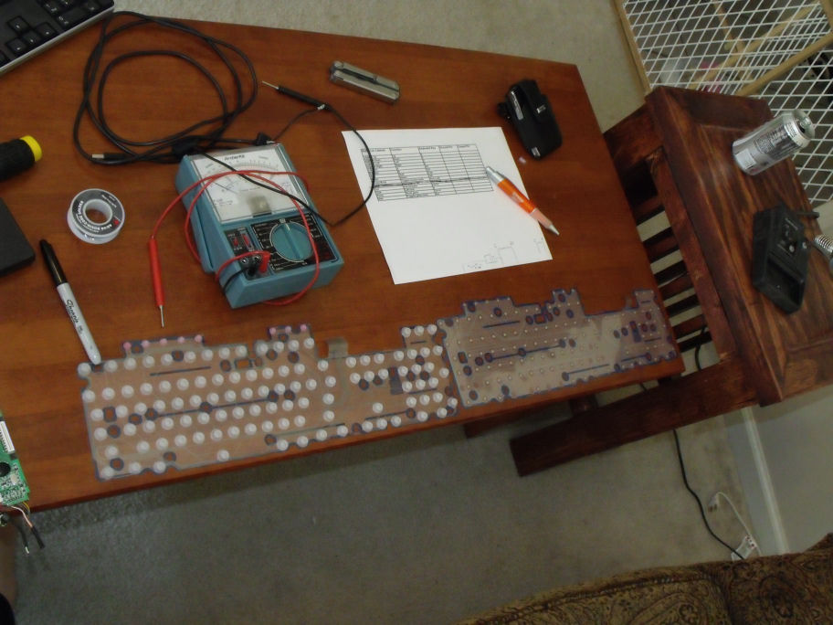


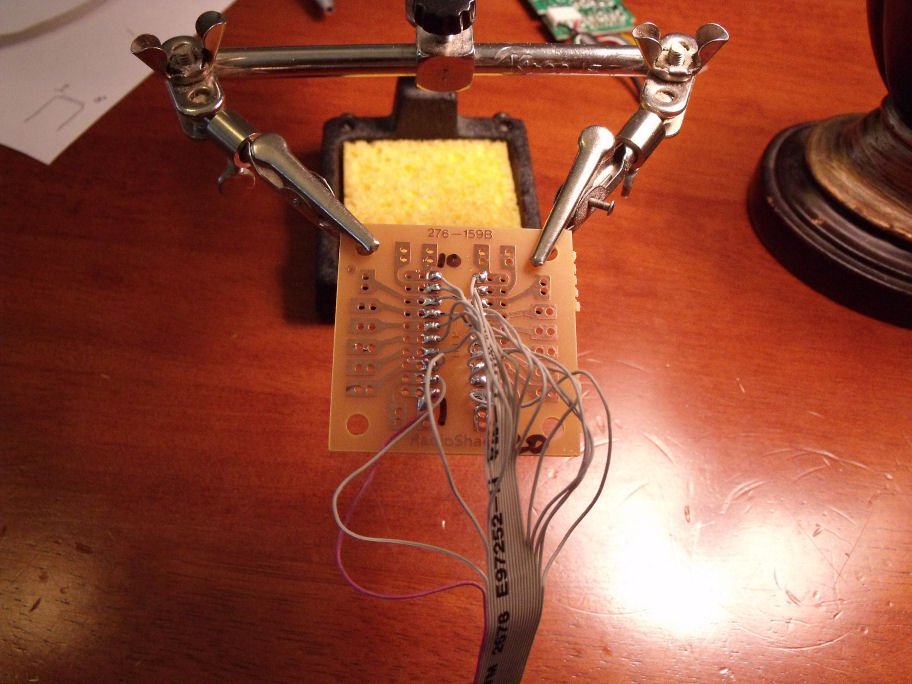


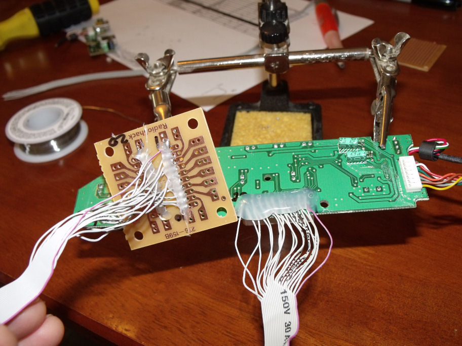

Now let's work on the interface for the joystick/buttons. This is how the controls will communicate with the PC.
You can buy encoders pre-made and save a lot of time, or you can do it on the cheap and spend a lot of time soldering. I prefer to do as much as possible myself, without buying special parts.
Take apart the keyboard and inside you will find a thin transparent piece of plastic film. It's actually two pieces that you must separate. After doing so, take a sharpie and mark the contacts that correspond to the keys you want to use.
I used the following keys: tab, esc, ctrl, alt, R, F4, enter, num lock, and the numbers 2,4,5,6,8, all from the num pad, that is very important. The numbers across the top of the keyboard will not work. This is because I used 2,4,6, and 8 as the up, down, left and right controllers for the emulator. By turning on sticky keys, these same numbers control the mouse cursor. The num locks enables/disables sticky keys. The number 5 key is the left mouse click. If you are using an 8-way joystick, you can also use the numbers 7,9,1, and 3 for the respective diagonals. I chose to keep it simple with a 4-way joystick since it was only going to emulate and old school NES.
Inside the emulator, you can choose which keyboard keys control what. This is what I used:
Main buttons:
UP-------------------num pad 8
DOWN--------------num pad 2
LEFT----------------num pad 4
RIGHT--------------num pad 6
START--------------enter
SELECT------------tab
B button------------ctrl
A button------------alt
Secondary buttons:
Mouse Mode----------num lock
Reset-------------------ctrl+R
Hide/show menu----esc
Mouse click-----------num pad 5
Exit----------------------alt+F4
Now that you have keys marked on the films, we need to trace the contacts out and see which pin corresponds to which contact. each film will have its own set of pins. One set will be grounds and the others will be opens. The film that is the grounds will have the least amount of pins. My grounding film had 8 pins and the open film had 20 pins. For example: Take the R key on the ground sheet and using a multimeter in continuity mode, find out which pin of the 8 pins leads to the contact for the letter R. In my case it was pin 5. Doing the same thing for the letter R on the open field shows the R key corresponds to pin 11. Now we know that if we make those two pins touch each other, that will activate the letter R. That is how a keyboard works. Repeat this for every keyboard key you are going to use, making a list of this information as you go.
solder wires between the contact pins you need and a prototyping circuit board from radioshack. A nice tip is once you have your solder point done, smother the entire thing in hot glue so no wire accidentally get pulled off.
Once the interface is complete, you will wire the buttons to the prototyping boards.
Make the Control Panel


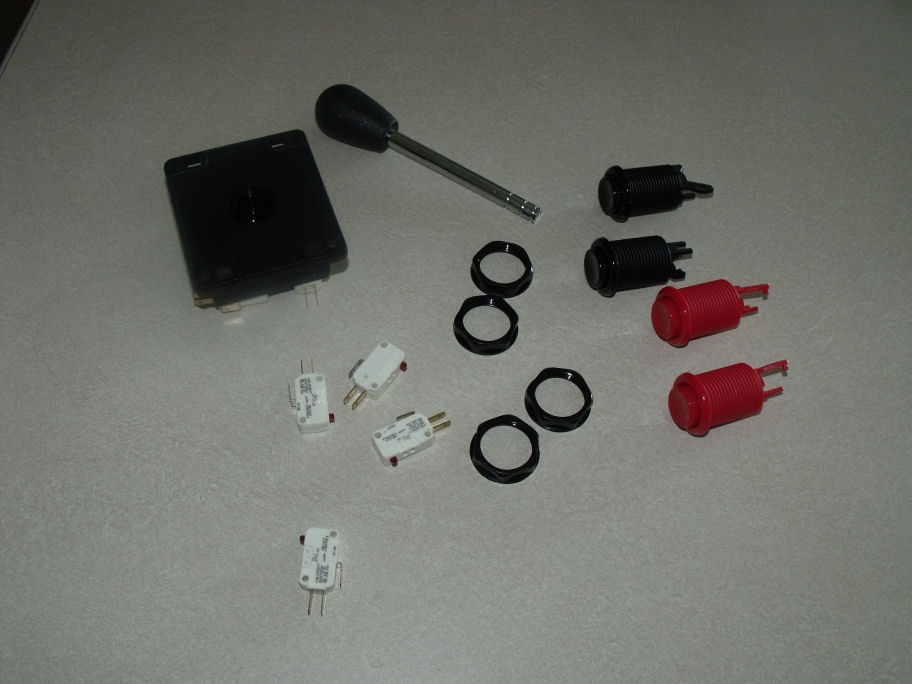
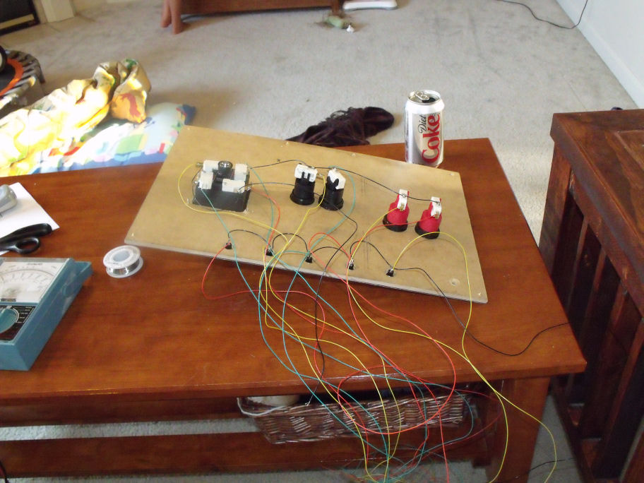

Now let's make the control panel. This will involve painting it, adding the joystick and buttons, and wiring them to the interface we created in the previous step.
Paint the entire board the base color of your choice
Mask out the design you want to use with painter's tape
Paint the board again with a different color.
Remove the painter's tape to reveal your design.
Drill the holes to insert the joystick and buttons into.
Install all buttons and joystick. You can additionally install a piece of plexiglass over the control board. I did this and it really made it look a lot nicer.
You can also label your buttons if you wish. I labeled the secondary buttons but chose to leave the main buttons unlabeled. For the text, I used rub on letters. You can get these from the scrap booking aisle at Hobby Lobby.
Now we need to connect the buttons to the interface.
At the base of each button and joystick is a microswitch. Wire the ground connection to the ground pin that corresponds with that button. Wire the normally open (NO) contact to the open end that corresponds. For example:
My A button corresponds to the keyboard key ALT. looking at my matrix, I see that the alt key is ground pin 6, open pin 19. for the A button microswitch, I solder a wire from the ground to pin 6 of my set of grounds. Then I solder a wire from the NO to pin 19 of my set of opens.
The A button is done, now repeat with all others.
Conceal Everything Inside the Cabinet

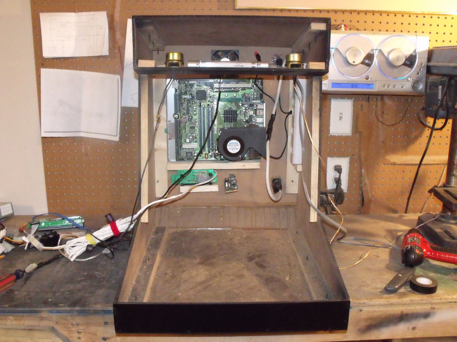

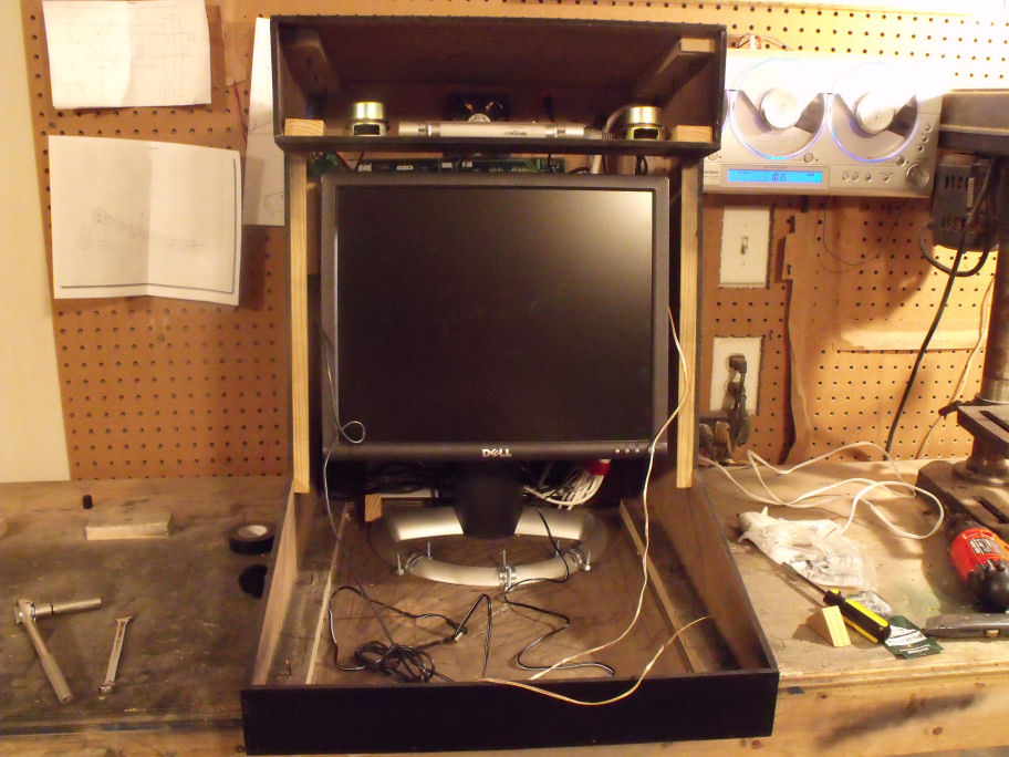

This step will vary depending on the size of your cabinet, size of your PC and monitor etc...
Basically, you shove all the components into the box.
I had to take my PC out of it's case and mount the components into the cabinet. There is a surge protector inside that the PC, monitor, speakers, and marquee light all plug into. I connected this surge protector to the male power plug that sits flush with the outside of the cabinet. I also put a rocker switch that turns the surge protector on and off. This way, one switch controls everything.
Add USB ports at this point. You can use a USB extension cable, just plug one end into the PC and leave the other end exposed for access outside the cabinet. The PC I used had an external USB control board, so I used that instead.
I made a Nes controller port that works with the PCs parallel port. There are plenty of instructions available for this online. It would require another instructable unto itself, so please look it up. Once the ports are wired up to the PC, leave the ends exposed at the back of the cabinet.
For speakers, I just took apart a set of desktop speakers. I installed them next to the marquee light, facing downward toward the screen. Be sure to drill several small holes in the wood that the speakers will be facing.
Connect a small fluorescent light kit and mount behind the marquee.
For the marquee design, I just printed out the logo I wanted and sandwiched it between two thin pieces of plexiglass.
Get the monitor in the exact spot you need and bolt it down.
Once all of this is done, test it out and if you are happy with the results, install the control panel and the plexiglass over the monitor.
For the bezel around the monitor, I used a sheet of plexiglass and spray painted the edges to hide everything except the viewable LCD area.
Finished Product
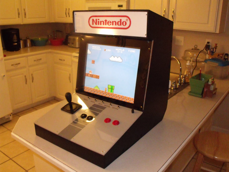
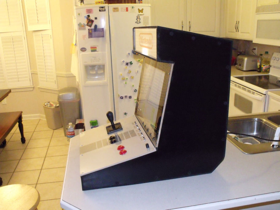


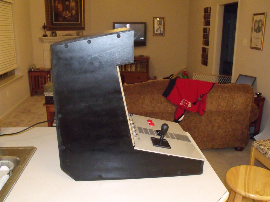
When it's all done, this is what you are left with.
Please feel free to ask any questions you may have. I will do my best to help you out.
Please feel free to ask any questions you may have. I will do my best to help you out.