HungryFuzz Distortion Module for Eurorack
111 Views, 0 Favorites, 0 Comments
HungryFuzz Distortion Module for Eurorack
.png)
It's the Modular for the Masses take on a germanium transistor Fuzz distortion! So many knobs, with voltage-controlled starve!
Supplies
You guys. The Fuzz Face distortion circuit has been listened to for more hours than possibly any other audio effects pedal. It's outrageously simple, physically, with like 8 parts, originally. The magic of this circuit is the transistors, classically germanium parts. Germanium transistors are only available as old parts, and while not super rare, there's basically no new ones being manufactured. Not that'll work in effects circuits like this one, at least.
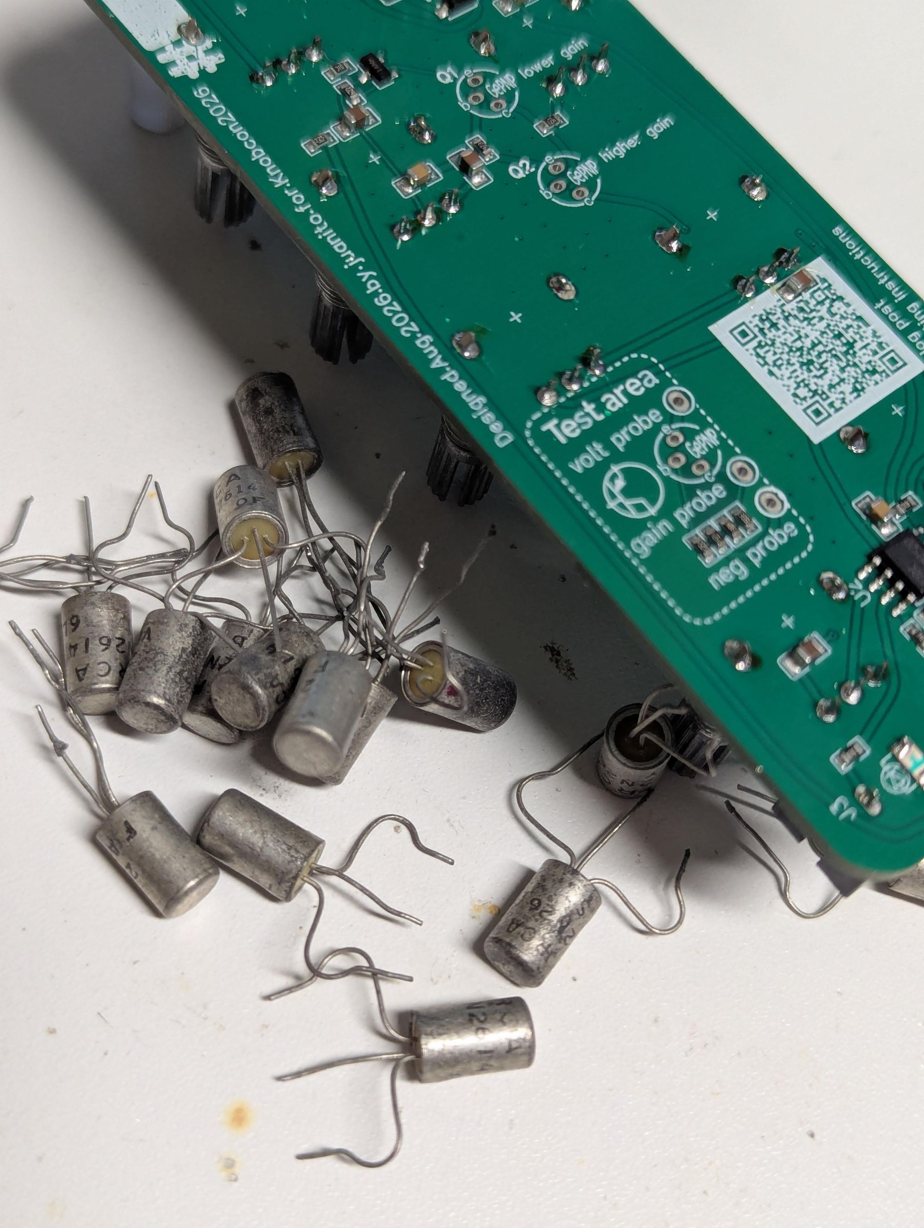
I got my filthy hands on a bag of NOS (and some desoldered, so UOS) germanium transistors! So clearly this circuit needs to exist.
The circuit at the core of this distortion pedal is simple. But the way germanium transistors behave is complex. There's a LOT of variability from one part to the next. The parameters of each part change with temperature. There's asymmetrical and voltage variability with how they clip a signal.
This circuit has a potentiometer at most of the junctions of the original circuit that can benefit from variability. So let's get building!
BOM:
- HungryFuzz SMT-assembled PCB and front panel
- 4 x SMD LEDs, 1206, 2 x green, 1 x red, 1 x blue
- 6.2V Zener diode, through-hole
- 1 x DuPont-style pin header, 2 x 5, 2.54mm pitch, for Eurorack power
- 1 x boxed multiturn trimmer, 100K
- 3 x mono Thonkiconn-style mono jacks
- 3 x vertical sealed box-style potentiometer, 100K
- 4 x 10K pots, just like the other pots
- 1 x JuanitoPot potentiometer, 100K
- 2 x germanium transistors!!!!!!!!!!!!!!!!!!!!!!!!!!!
SMD LEDs
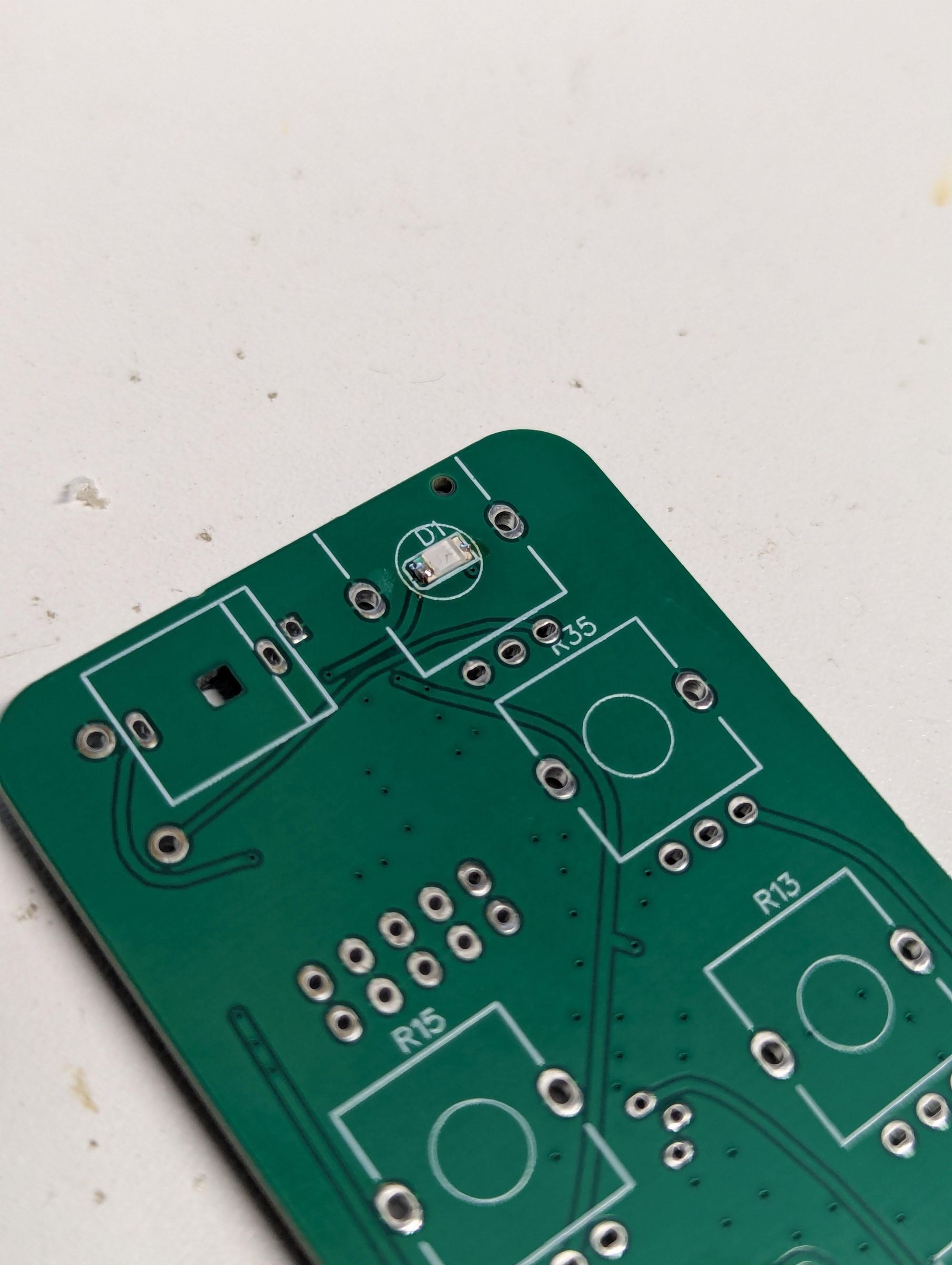
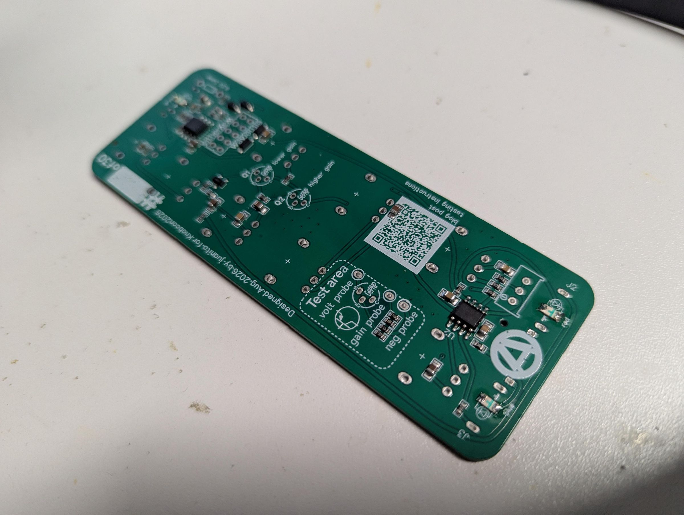
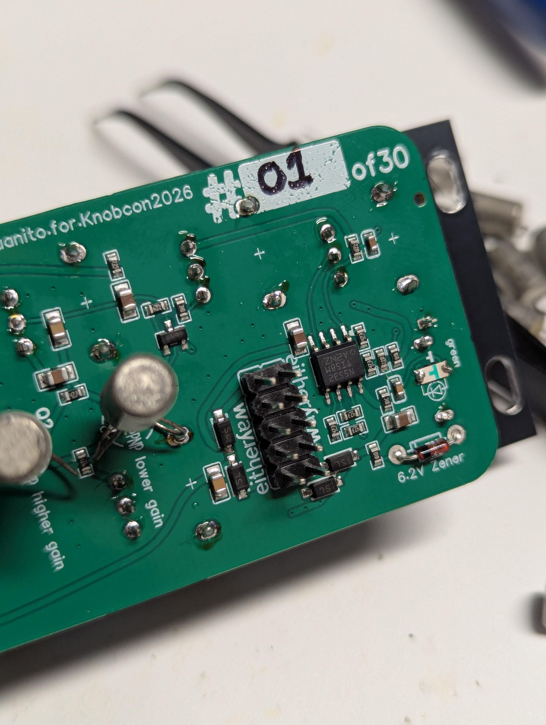
Okay first thing, put the jack LEDs into the little square holes under each jack. Modular For The Masses color standard is: red - primary inputs; green - CV inputs; blue - primary output; pink or orange - OTHER. Leave these off if you want, no biggie. Be sure to match the polarity of the LEDs to the footprint, matching the LED to the markings on the PCB.
Then, flip the PCB over and find the spot where another LED goes. Solder one of the green LEDs right there, being careful to get the polarity right.
Zener
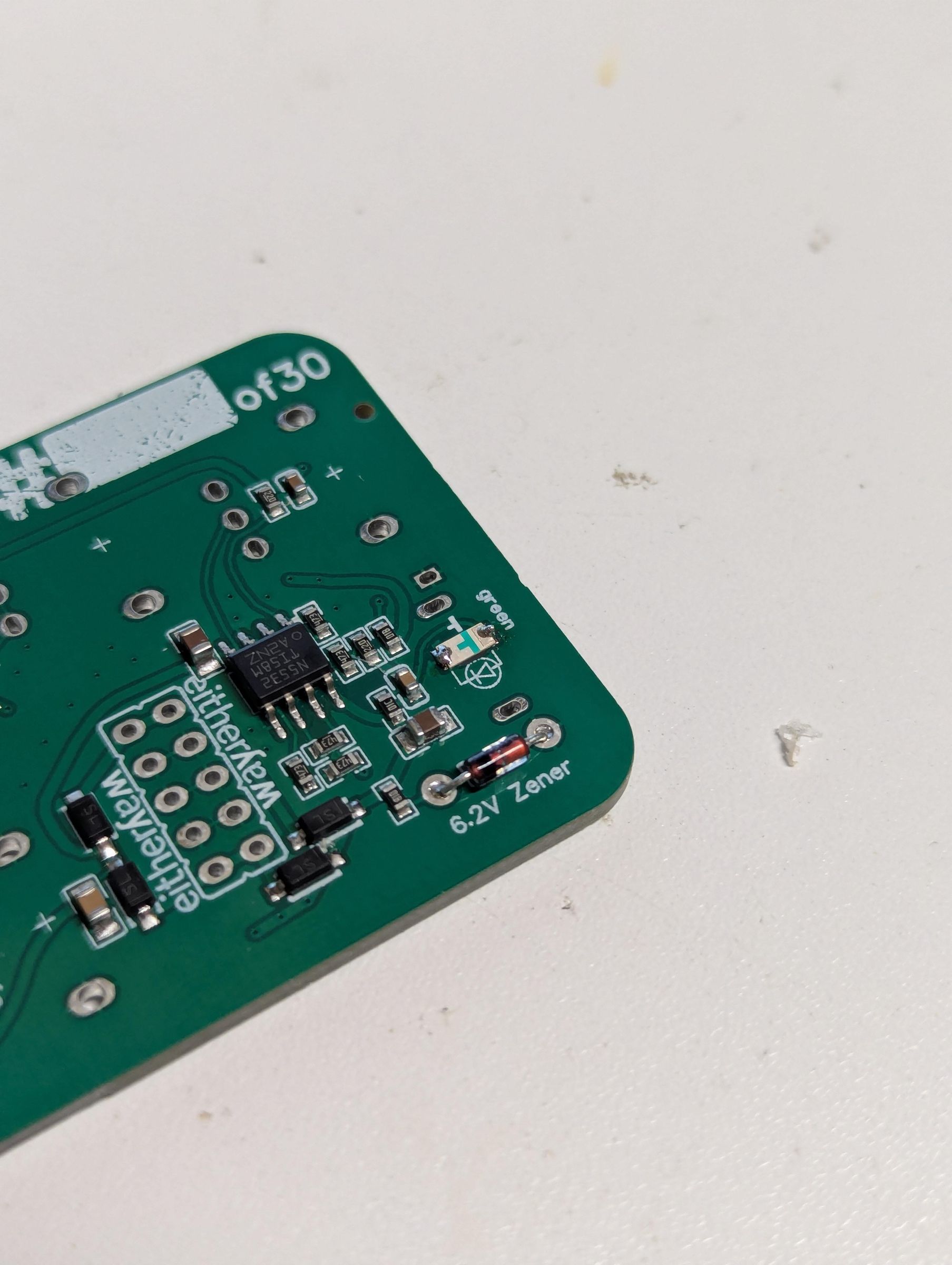
Clarence Zener is the physicist who gave the Zener diode its name. Zener diodes pass current normally from anode to cathode, dropping the typical 0.7V, but if you put enough voltage into the diode the OTHER way, at the cathode, the Zener will pass current.
Anyway, in this circuit, the Zener is used to set the highest voltage available to the "starve" portion of the circuit. This 6.2V value means that the distortion core will be running just a touch below 12V at maximum voltage, close enough to the 9V of the original circuit using a 9V battery.
Power Header
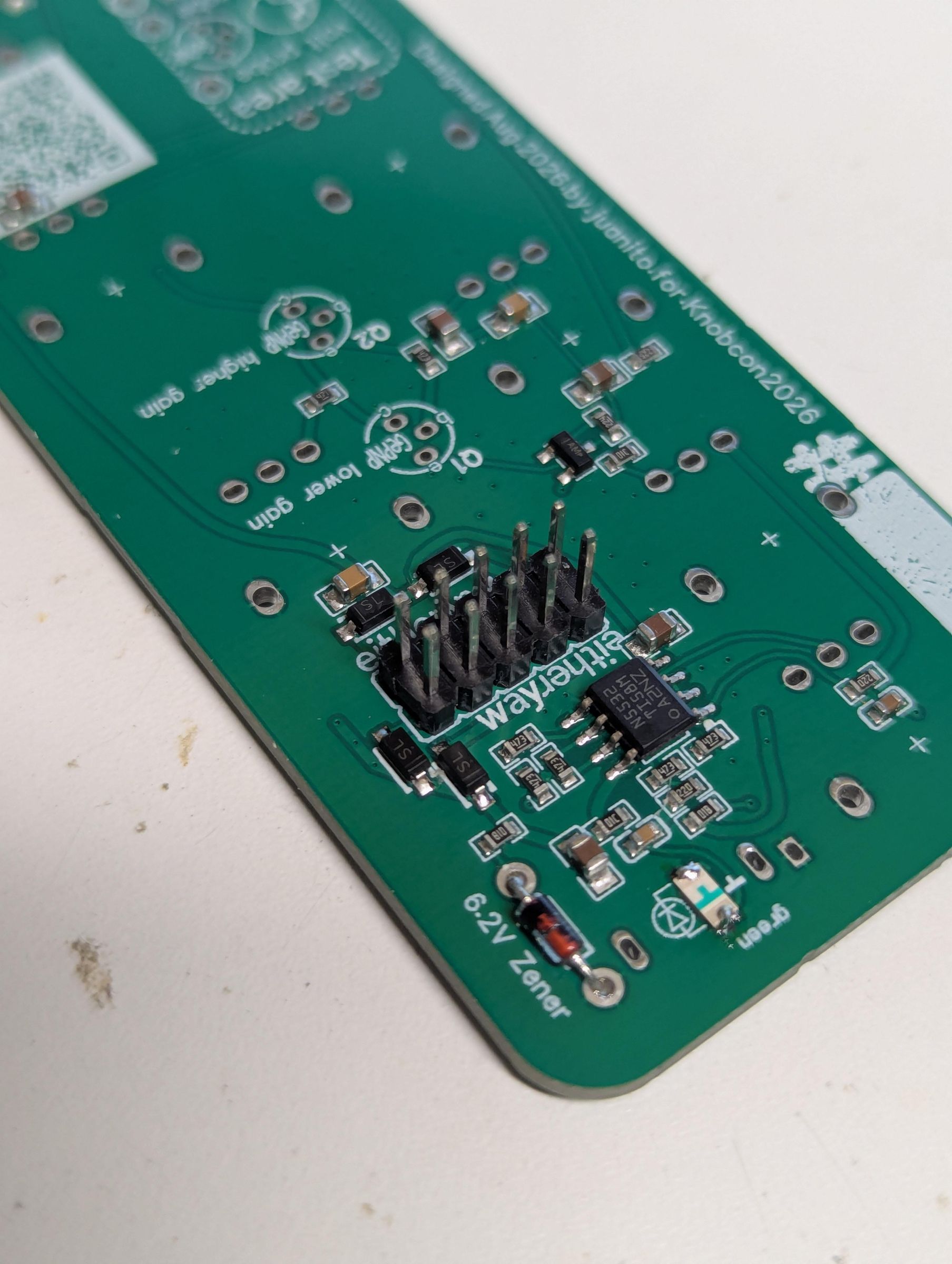
Cram that ten-pin header into the PCB, and solder it in place! Easy peasy!
Trimmer
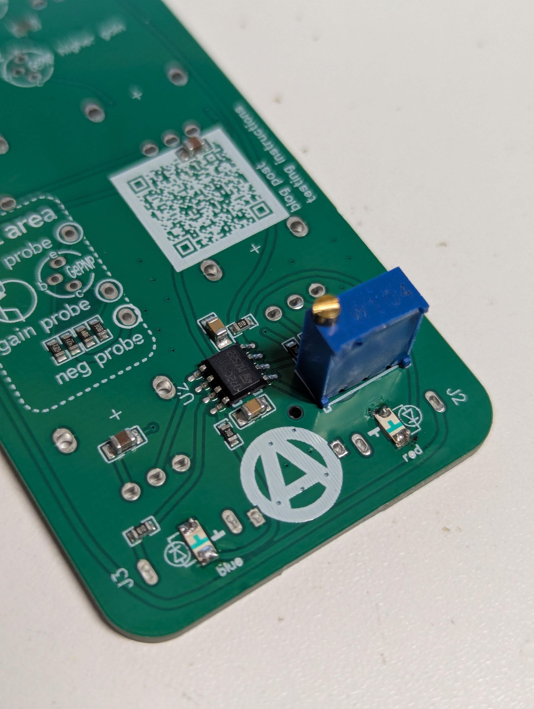
The variability of germanium transistors will change the output level of this module. This little trimmer guy allows you to calibrate in enough output voltage swing to satisfy your Eurorack signal needs.
Thonkiconns
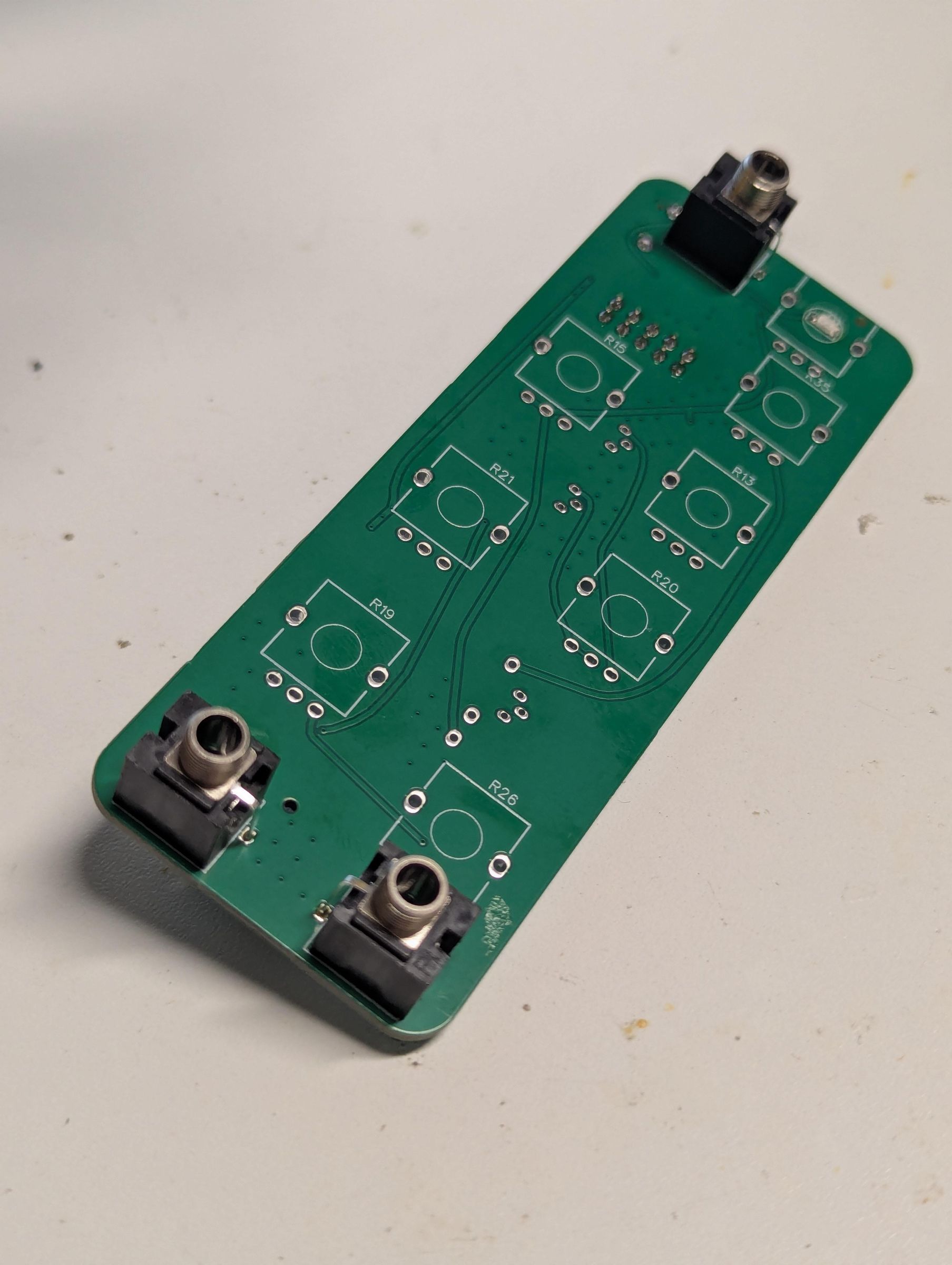
Three Thonks go in here. Do that now.
Pots!
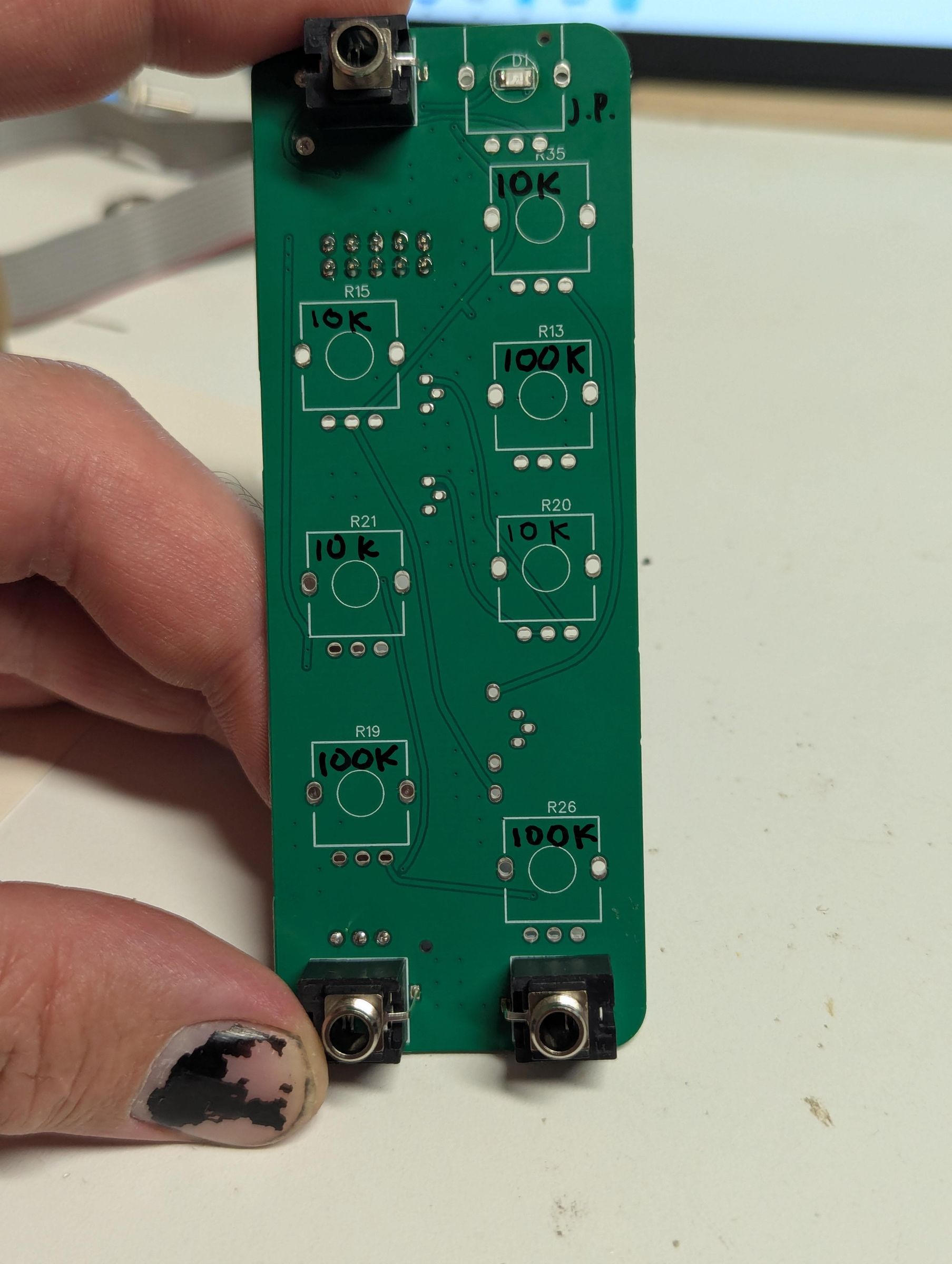
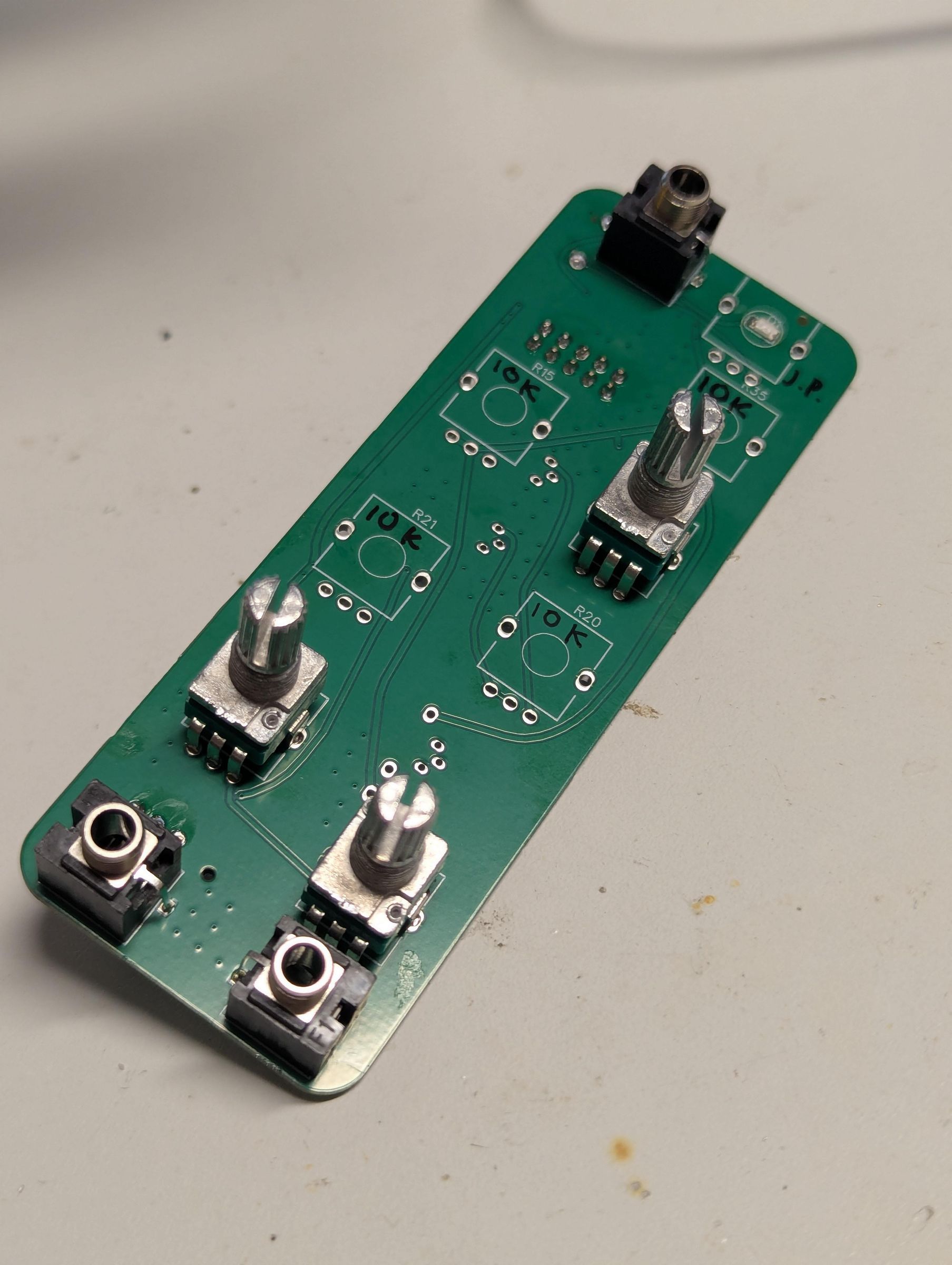
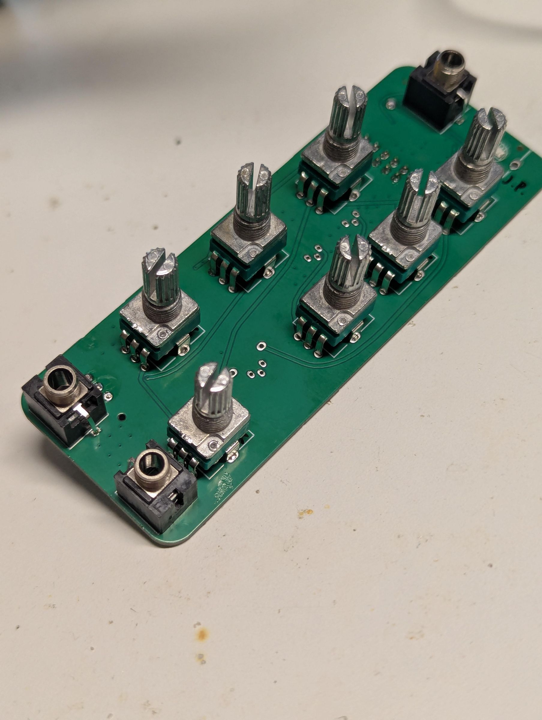
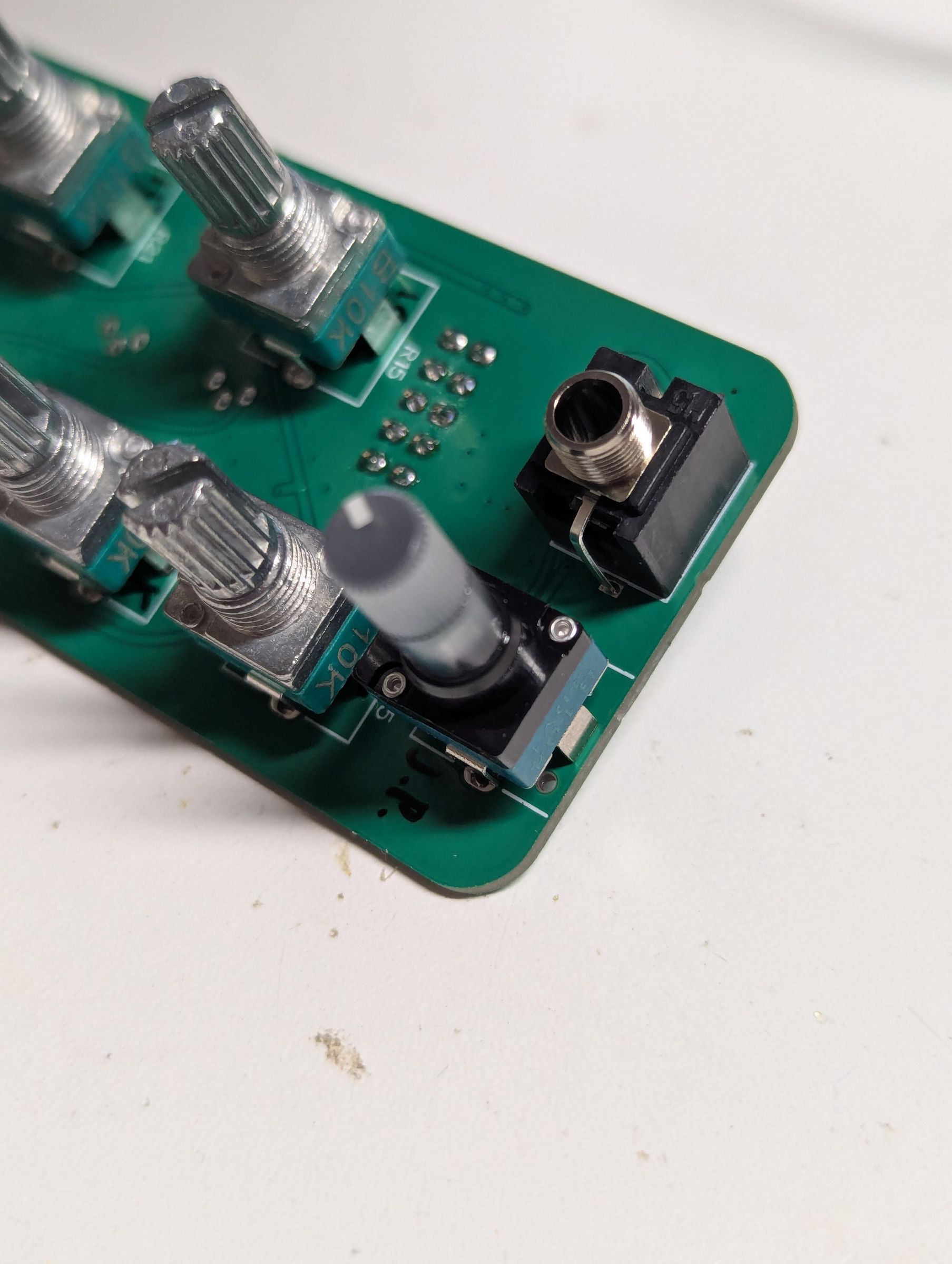
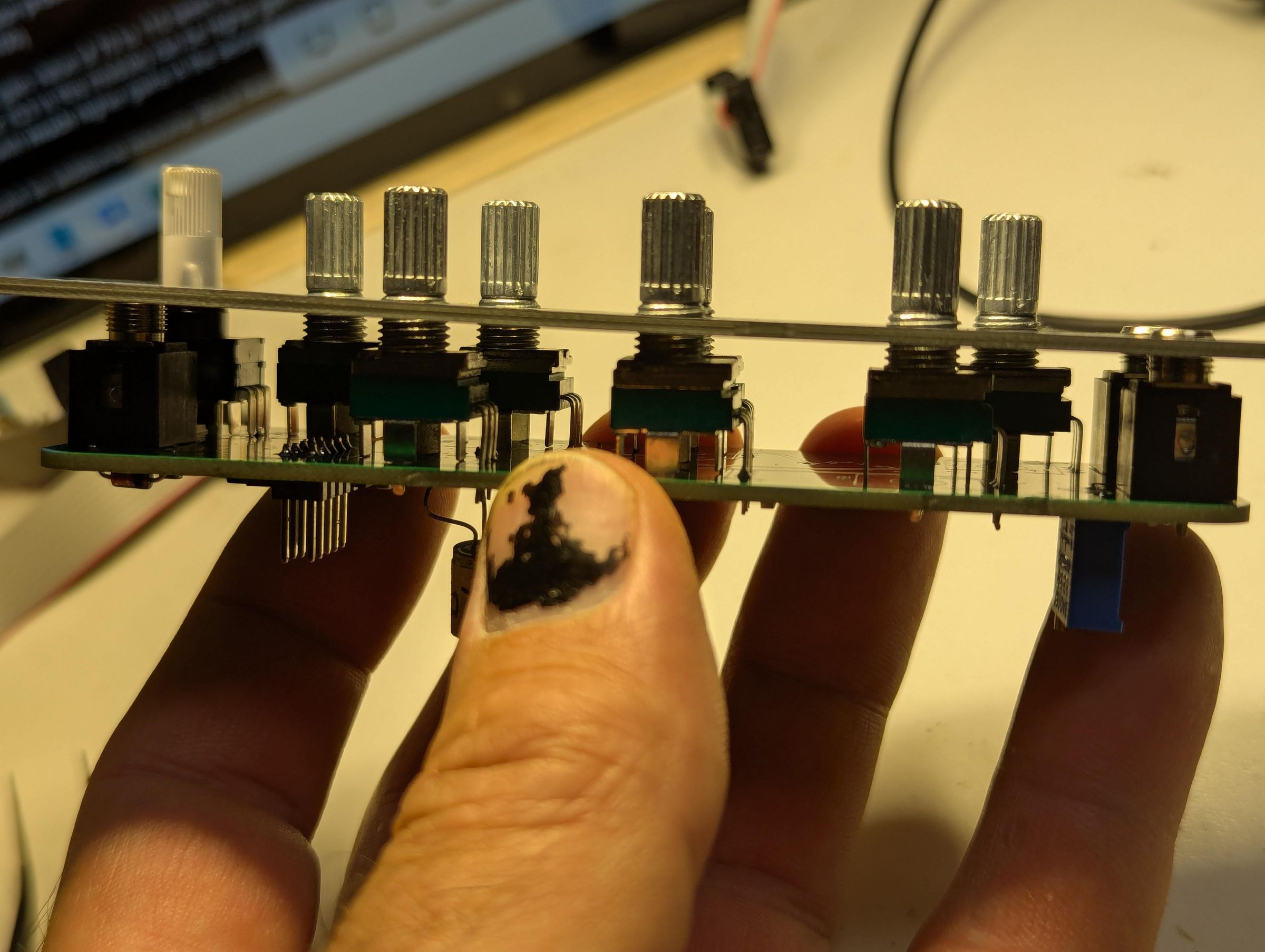
Okay I neglected to put values for the pots in the silkscreen, so refer to the first picture here for values. Or maybe I wrote them on the PCBs.
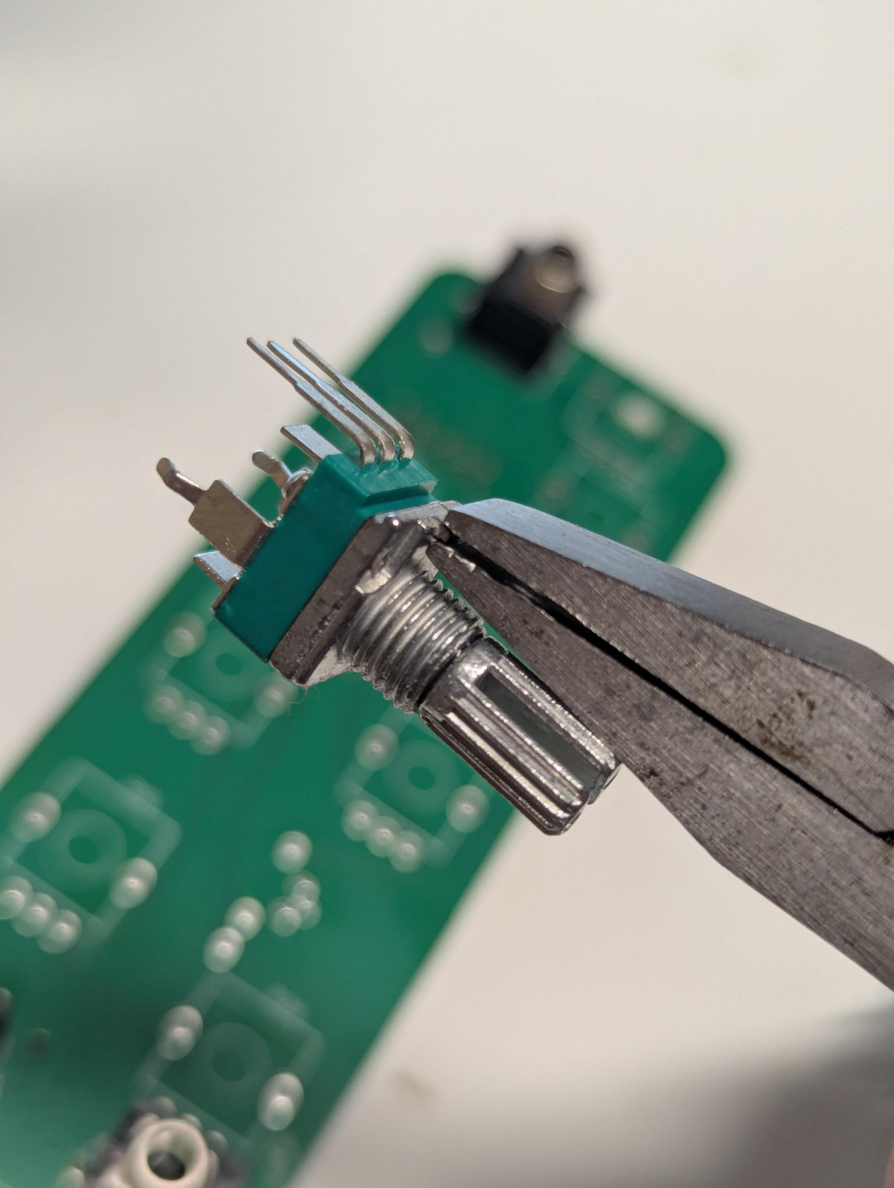
Look for locator tabs on each potentiometer, and if present, get them gone, out of here, nobody wants you, locator tab why are you even????
Next picture, I've installed the three 100K regular pots.
Next pic shows the 10K pots also installed.
Next picture shows the JuanitoPot (also 100K) installed. JuanitoPots don't have locator tabs because they're too smart for that malarkey.
Last picture? It's putting the faceplate front panel on, and just giving it a glance to make sure we removed all those locator tabs. We did it!
Good Golly! Germanium
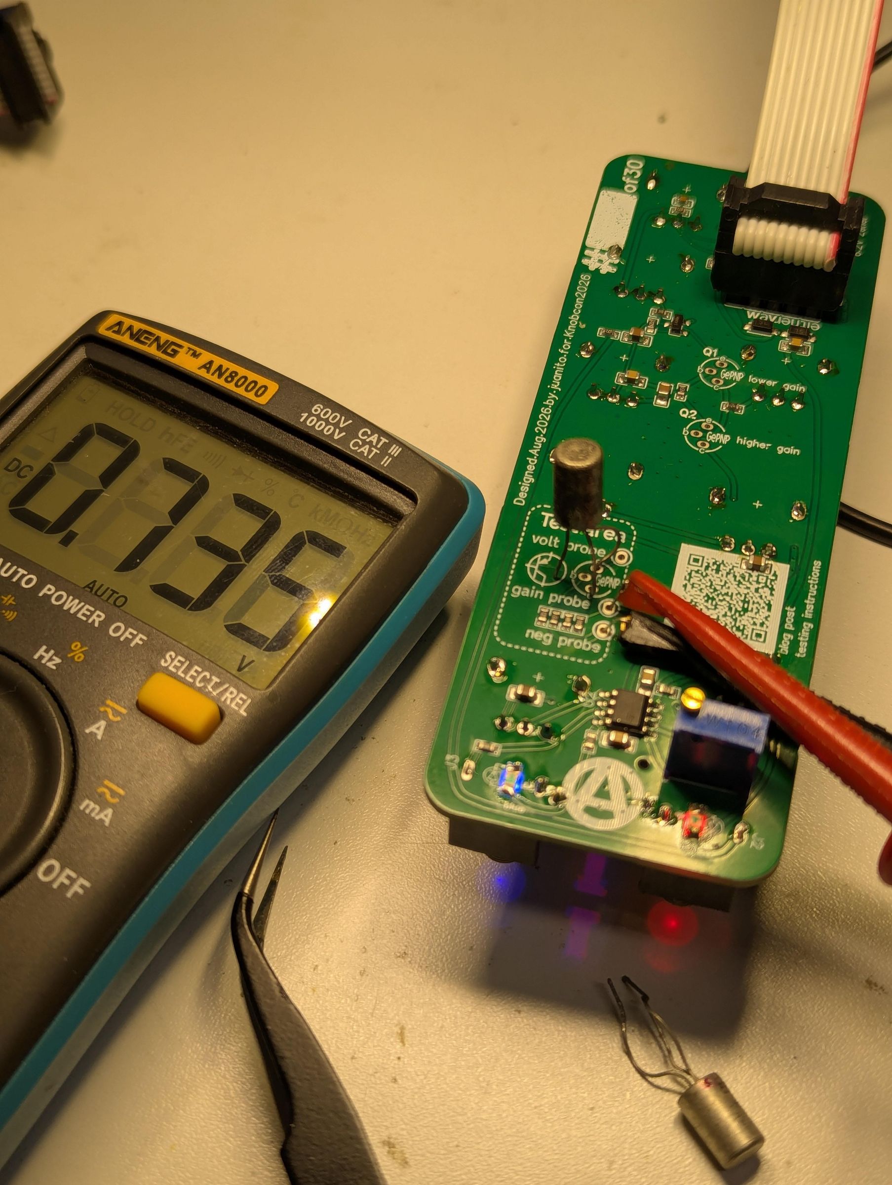
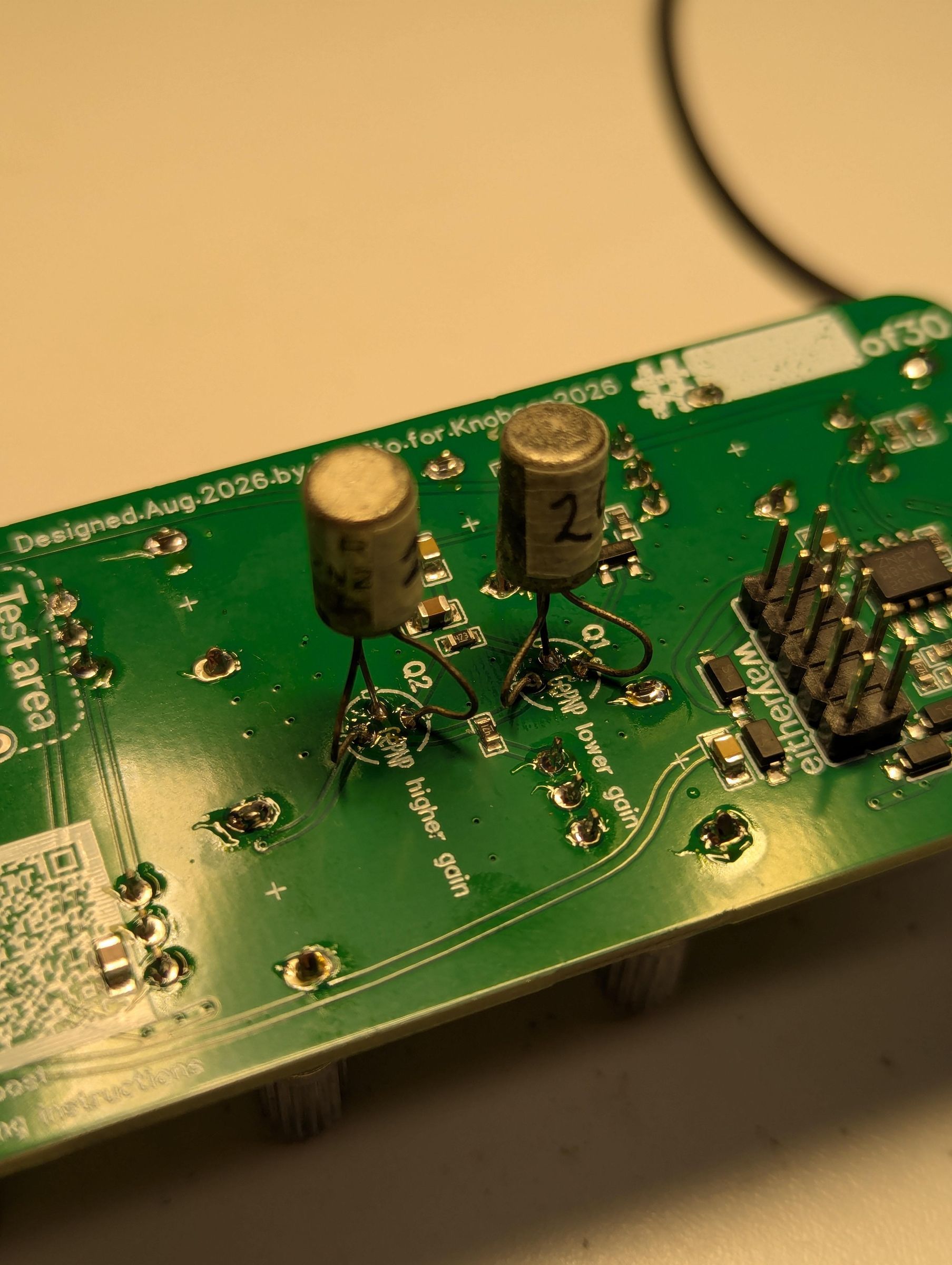
If you're at the Knobcon2026 build workshop with me, I will have my bag of germanium transistors already tested and labelled. Grab a pair that tickles your fancy.
What fancy? Well, according to the germanium-transistor-distortion-pedal community:
- transistors in the 70 to 110 range are the sweet spot
- the higher-value transistor should be installed in the second spot (Q3 in this circuit)
- some builder have been happy with the second transistor having a much higher gain value
- A guy named Steve Daniels from Small Bear Electronics has some very expert opinions on this circuit, and what transistors you should select. Follow this link to read all about it, but to sum up, he says to stick with 70 to 85 for the first transistor, 120 to 140 for the second. If you like a more "squishy" and "compressed" sound, choose an even higher gain device for the second transistor, 150 to 190. He goes on to point out that gain values are the important parameter, not the particular part number. Mix and match!
Other types of transistor will work in this circuit, and experimentation is encouraged! But what if you're not here? What if you were digging up a pet cemetery for some reason and found an ice cream bucket filled with moisture-damaged new-old-stock germanium transistors? READ ON!!!
The QR code on the module takes you to this blog post, which is where I'm copying the following instructions from.
- Connect your mostly-completed HungryFace to a Eurorack power supply
- Insert the top and bottom legs of your transistor into the footprint. Don't solder it in place, and don't put the base (middle leg) in yet.
- Attach the negative probe of your digital multimeter to the "neg probe" hole or pin if you installed a pin for some reason. Set the multimeter to DC volts
- Attach the positive probe to the "volt probe" and carefully adjust the "Starve" knob of your module until the voltage read between those two pins is 9.00 volts. Don't be too annoyed if it's not exact, the as long as it's fairly close
- Move the positive probe of your multimeter to the "gain probe" pin or hole. Write down the voltage you're seeing between gain probe and neg probe. Write it down and label it "leakage". If this value is more than 2.472 volts, set that transistor aside, it probably won't be useful for this circuit
- Next, put the base of the transistor in the middle pin of the footprint. Wait a few seconds for the transistor to cool (the gain and leakage of these little guys is very dependent on temperature) and take a reading. Write this value above the "leakage" value, and label it "gain + leakage". Do the subtraction problem you've got there, and you've arrived at your gain number (except multiply it by 100)
Important info about these transistors:
They can be damaged by heat. Leave the transistor legs bent out like they are to allow soldering without heating up the fragile insides too much. Solder quickly, do NOT linger.
When you've got the transistors soldered in place, carefully ensure that they're not likely to touch each other, and will hold the transistor securely in place.
Finishing Up!
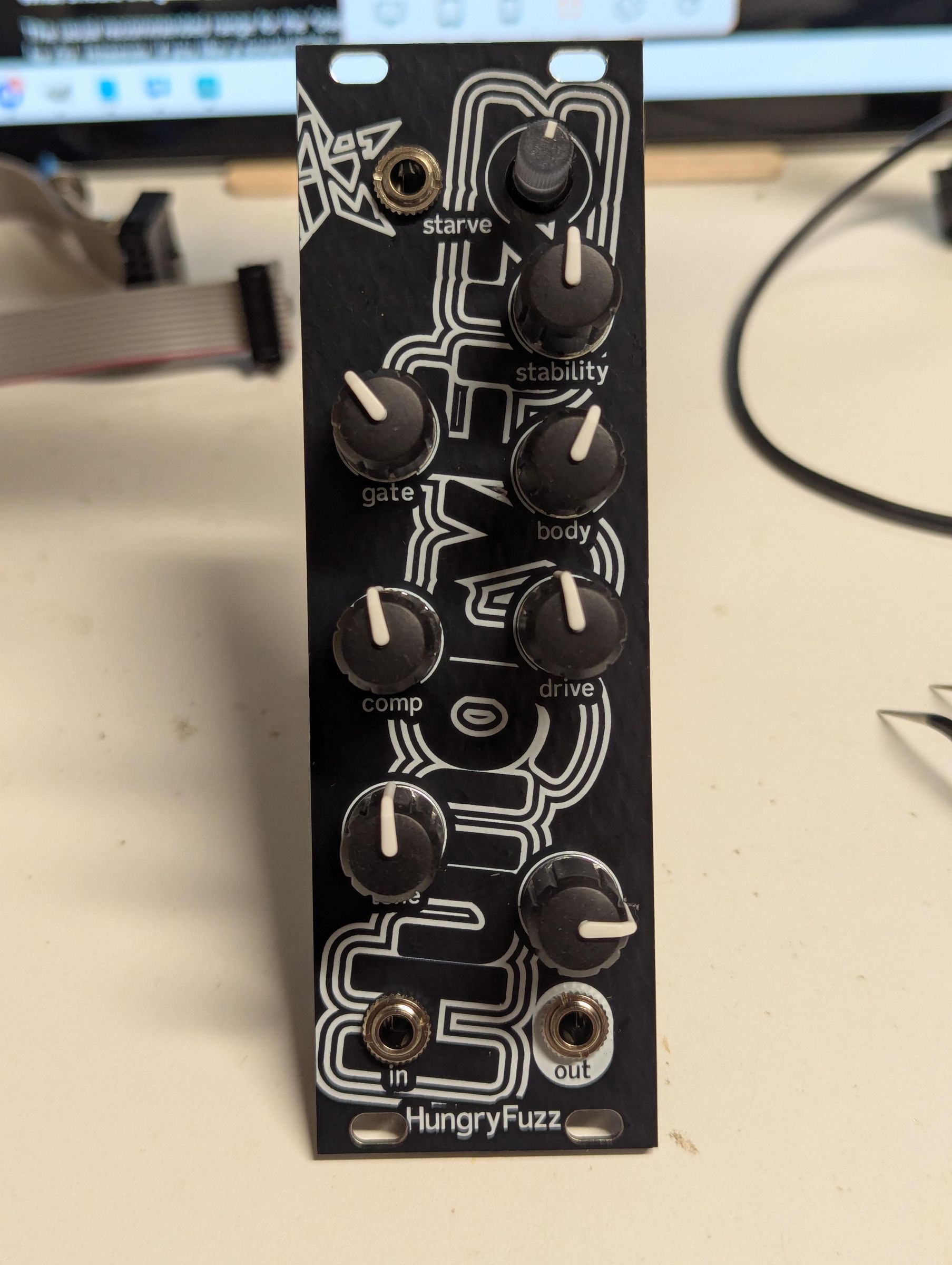
It's time to install all the knob caps! Then, write the serial number of your brand new module!
Enjoy!