I Built a 3D-Printed Ice-Cooled Turbine Fan
by Bogdan Bulat in Outside > Beach
43 Views, 0 Favorites, 0 Comments
I Built a 3D-Printed Ice-Cooled Turbine Fan
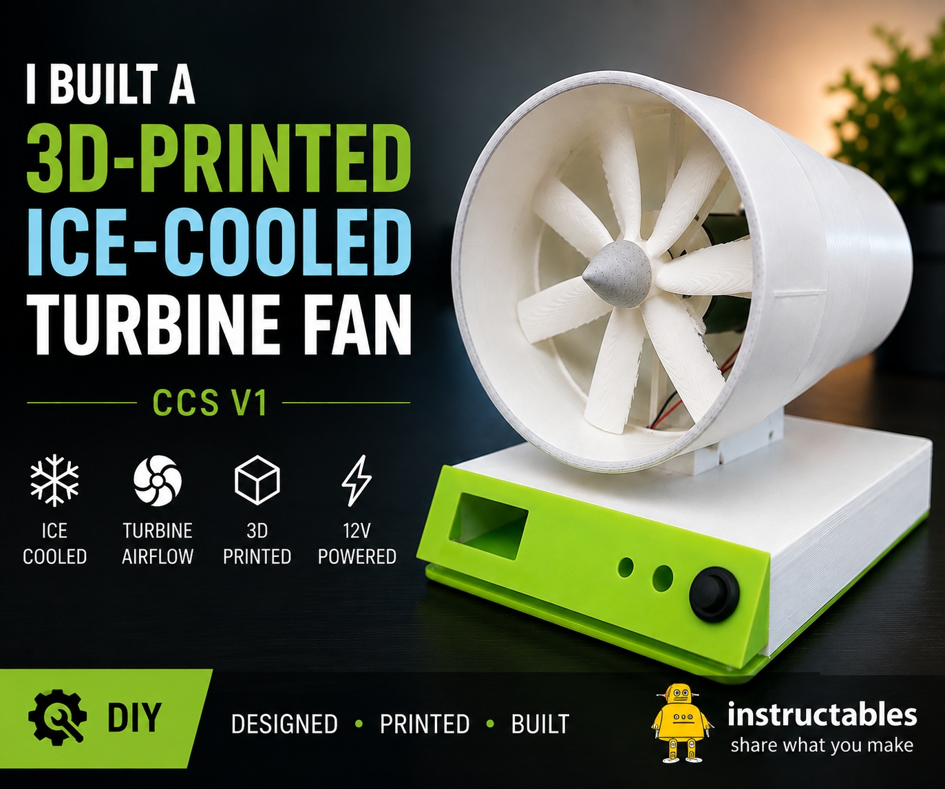
ummer heat was the starting point for this project. I wanted to build something more interesting than a conventional desktop fan: a compact cooling system that combines forced airflow with ice, while also having a distinctive turbine-inspired design.
The result is the CCS V1, a 3D-printed cooling system built around a high-speed DC motor, a custom impeller and an ice chamber.
The motor generates the airflow, while the frozen chamber provides a simple cold thermal mass that helps reduce the temperature of the air.
One of the main goals of this project was to design the mechanical parts specifically for the device instead of simply assembling an existing fan. The housing, turbine structure, mounting system and cooling chamber were designed as parts of the same system.
This is very much a V1 prototype. My original concept included more advanced electronic control, but during final integration I simplified the electronics to a reliable 12 V ON/OFF system. This allowed me to concentrate on getting the mechanical design, airflow and ice-cooling concept working first.
During my initial tests, I measured an approximate temperature reduction of 2.3 °C to 3.4 °C, depending on the temperature of the frozen chamber. These measurements were made with a medical thermometer, so they should be considered approximate rather than laboratory-grade results.
A future V2 can build on this prototype with variable fan speed, temperature sensors, electronic controls and further airflow optimization.
Supplies
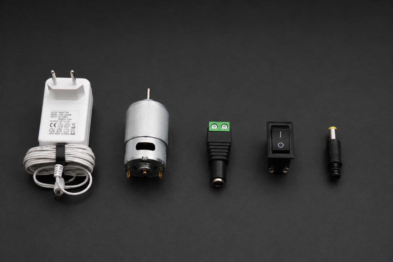
The CCS V1 combines custom 3D-printed parts with a simple 12 V electrical system.
Main Components
- 12 V DC motor
- 12 V power supply
- ON/OFF switch
- DC barrel jack connector
- DC barrel plug
- M8 bolt
- M8 nut
- 2 original motor mounting screws
- Electrical wire
3D-Printed Parts
- Main base
- Three-part turbine housing
- Motor support
- Impeller
- Turbine nose cone
- Front panel
- Ice chamber
- Ice chamber cover
- Top enclosure/cover
Materials
- PLA filament
- Adhesive for assembling the printed parts
- White PVA glue
- Small amount of water for the prototype sealing mixture
- Water for freezing inside the cooling chamber
Tools
- 3D printer
- Soldering iron
- Screwdrivers
- Wire cutters/strippers
- Multimeter
- Computer with CAD and slicing software
- Basic hand tools
Designing the CCS V1
I started the project by designing the complete cooling system before building it.
The basic idea was simple: use a motor-driven impeller to generate airflow and combine it with a frozen chamber to create a localized cooling effect.
However, packaging everything into a compact enclosure required considerably more work.
I wanted the fan section to look more like a small aircraft turbine than a conventional desktop fan. This influenced the shape of the external duct, the internal motor support, the impeller and the nose cone.
The design also had to provide enough space for the motor, wiring, power connector and cooling chamber while keeping the different sections accessible during assembly.
Another important consideration was printability.
Instead of printing the entire turbine as one large and difficult component, I divided it into three separate sections. These could be printed individually and permanently joined afterward.
The base was also designed with a mounting point for the complete turbine. Once inserted, the turbine can be mechanically secured from underneath using an M8 bolt and nut.
This modular approach made the CCS V1 easier to print, assemble and modify while developing the prototype.
3D Printing the Parts
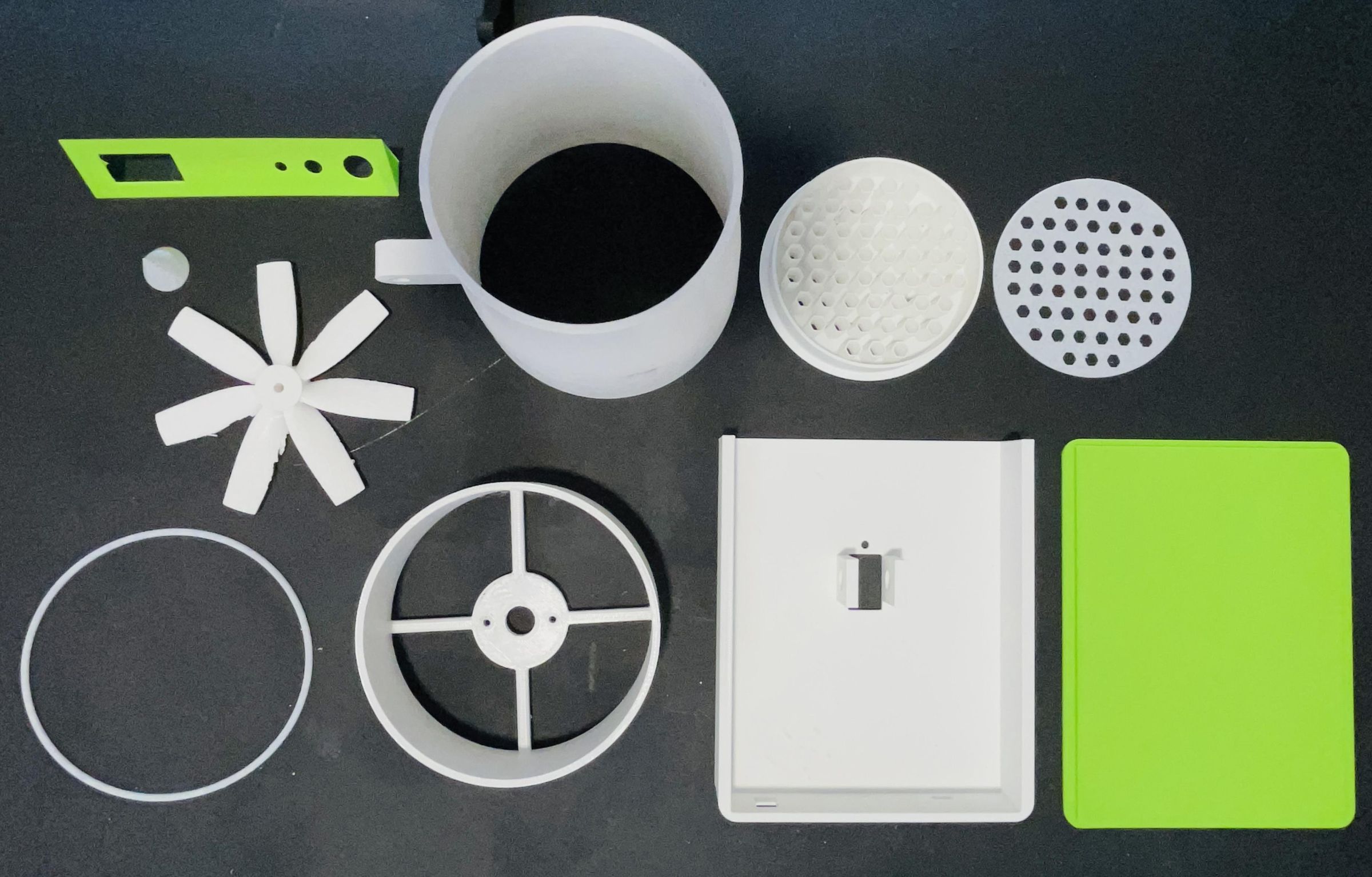
Once the CAD design was ready, I moved on to manufacturing the enclosure and turbine components.
Most of the CCS V1 structure is 3D printed. This made it possible to create the unusual turbine geometry and integrate mounting features directly into the enclosure.
The turbine was printed as multiple parts rather than one large component. This made the geometry easier to manufacture and also simplified assembly.
The impeller was one of the most important printed components. It needed to fit the motor shaft correctly while remaining lightweight enough to rotate at high speed.
During development, I experimented with different impeller geometries before settling on the final version.
After printing, I removed the supports and cleaned the necessary contact surfaces.
Before beginning assembly, I also checked all the important fits, particularly:
- Motor and motor support
- Three turbine sections
- Impeller and motor shaft
- Turbine and main base
- Ice chamber
- Front panel
- Top cover
Checking these parts before using glue saves a lot of trouble later in the build.
Installing the DC Motor
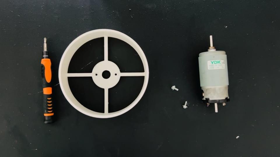
For this prototype, I used a DC motor originally intended for a professional embroidery machine.
It is a powerful, high-quality motor, but it is also relatively expensive and definitely not necessary to reproduce this project.
If you build your own version, I recommend using a more affordable DC motor with similar dimensions and suitable voltage, speed and power.
If your motor has different dimensions, you may need to modify the motor support and turbine design slightly to match its diameter, shaft position and mounting points.
In my build, the motor fits directly inside the printed support.
I first inserted the motor into its correct position, making sure that the shaft was centered and pointing toward the front of the turbine.
The motor already came with two mounting screws, so I reused these original screws to secure it to the printed motor support.
I tightened both screws until the motor was firmly secured, without overtightening them against the printed plastic.
Finally, I checked that the motor shaft could rotate freely and left the two motor wires accessible for the electrical connections.
Assembling the Three-Part Turbine
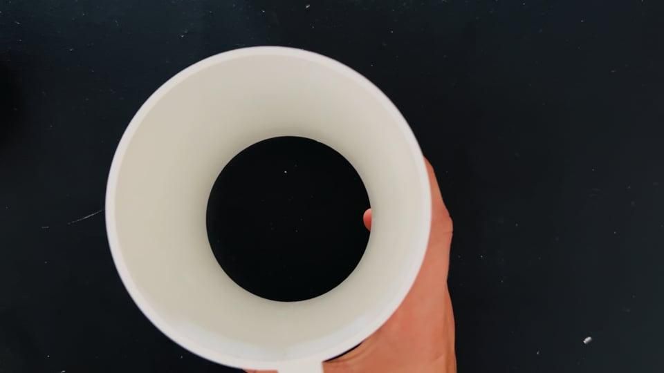
The turbine housing consists of three separately printed sections.
Before applying adhesive, I first placed all three pieces together without glue.
This dry fit allowed me to check their orientation and make sure that the edges aligned correctly.
Once I was satisfied with the fit, I separated the pieces and applied adhesive to the joining surfaces.
I joined the first two sections and carefully aligned them. I then added the third section to complete the turbine housing.
Alignment is important because large differences between the sections could affect both the appearance of the turbine and the internal airflow path.
I held the components in their correct positions while the adhesive began to set and then allowed the assembly to dry.
Once complete, the three individual printed components form a single turbine housing.
Installing the Impeller and Nose Cone
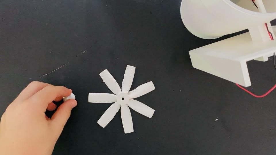
With the motor and turbine assembled, the next step was preparing and installing the impeller.
The impeller consists of two parts: the main blade assembly and a small nose cone that fits in its center.
First, I applied a small amount of glue to the nose cone and carefully attached it to the center of the impeller.
I made sure that the cone was properly centered before allowing the adhesive to set.
The nose cone is mainly an aesthetic feature. It helps give the front of the CCS V1 the appearance of a small aircraft turbine and creates a cleaner finished assembly.
Once the nose cone was securely attached, I installed the complete impeller onto the DC motor shaft.
I carefully pushed it into position while keeping it as straight and centered as possible.
Correct alignment is particularly important because the motor can operate at high rotational speed. An incorrectly centered or unbalanced impeller can produce excessive vibration.
After installation, I manually rotated the impeller several times to make sure that none of the blades touched the turbine housing.
Mounting the Turbine to the Base
With the motor, impeller and nose cone assembled, the complete turbine can now be installed onto the main base.
First, I passed the two motor wires through the opening in the base.
These wires need to remain accessible inside the enclosure because they will later connect to the 12 V power circuit.
I then carefully inserted the turbine into its mounting hole in the base, making sure that it was properly seated and correctly aligned.
To prevent the turbine from moving during operation, I designed a simple mechanical locking system using an M8 bolt and nut.
From the underside of the base, I installed the M8 hardware through the mounting point and tightened it until the turbine was firmly held in position.
There is no need to overtighten it. The goal is simply to prevent the turbine from rotating or moving because of motor vibration.
Finally, I checked that the turbine was straight, that the motor wires were not trapped and that the impeller could still rotate freely.
The main turbine assembly was now complete.
Wiring the Motor and Front Panel
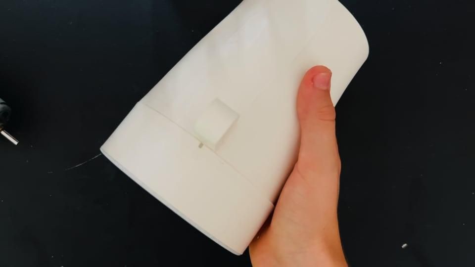
For the final CCS V1, I decided to keep the electrical system as simple and reliable as possible.
The final version uses:
- 12 V DC power supply
- DC barrel jack
- ON/OFF switch
- DC motor
The ON/OFF switch is installed in the front panel, allowing the turbine to be controlled directly.
The basic electrical circuit is:
12 V DC jack → ON/OFF switch → DC motor → DC jack return
One motor wire is connected through the ON/OFF switch to the appropriate terminal of the DC jack.
The second motor wire completes the circuit back to the other terminal of the DC connector.
When the switch is ON, the motor receives power and rotates the impeller.
When the switch is OFF, power to the motor is interrupted.
Once the electrical connections were complete, I arranged the wires inside the base so that they could not interfere with any moving parts.
I also installed the switch in its corresponding opening in the front panel.
Before applying power, I carefully inspected the connections for exposed conductors, loose wires or possible short circuits.
Important: Check the polarity of your DC connector and make sure your motor is suitable for your chosen power supply before connecting it.
Preparing the Ice Cooling Chamber
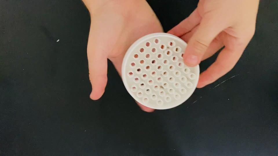
The ice chamber is what turns the CCS V1 from a simple turbine fan into an ice-assisted cooling prototype.
Because the chamber is 3D printed, I wanted to add an additional internal coating to help reduce possible leaks through small gaps, joints or micropores between printed layers.
For this V1 prototype, I used white PVA glue mixed with a small amount of water.
This should be considered a prototype sealing method, rather than a permanent waterproofing solution for repeated freeze/thaw cycles.
I placed some white PVA glue in a container and added only a small amount of water.
The objective was to make the glue slightly more fluid so that it could spread over the internal surfaces more easily, not to make it extremely watery.
I then poured a small quantity of the mixture through the opening in the chamber.
Next, I temporarily positioned the cover and carefully rotated and shook the chamber so that the mixture could spread across the internal walls, corners and joints.
The objective is to leave a thin internal coating rather than filling the chamber with glue.
I then removed/drained any excess mixture and allowed the coating to dry completely.
Once dry, I fixed the chamber cover in its final position.
Water can then be introduced into the chamber through its filling opening.
The chamber is placed in the freezer until the water inside is completely frozen.
This creates a reusable cold thermal mass for the CCS V1.
For a future version, I would investigate a more durable waterproofing method designed specifically for repeated contact with water and freeze/thaw cycles.
Final Assembly
With the turbine, electrical system and ice chamber prepared, it was time to complete the CCS V1.
First, I secured the 12 V DC jack connector in its final position on the enclosure.
I checked that it was firmly mounted and that its wires could not interfere with the turbine or motor.
Before closing the enclosure, I performed one final inspection of the inside of the CCS V1.
I checked:
- Motor mounting
- Turbine mounting
- Impeller clearance
- M8 fixing
- ON/OFF switch
- DC jack
- Electrical connections
- Cable routing
- Ice chamber position
Next, I positioned the front panel on the main base.
Once I was satisfied with its fit and alignment, I applied adhesive to the contact surfaces and carefully glued the front panel into position.
Finally, I installed the top cover, making sure that it fitted correctly and that no wires were trapped between the printed components.
After one final visual inspection, the construction of the CCS V1 was complete.
It was now ready for testing.
Testing the CCS V1
After completing the assembly, I tested the CCS V1 with the frozen cooling chamber installed.
I first tested the turbine without concentrating on cooling performance.
I checked that the motor ran correctly, that the impeller did not touch the turbine housing and that there were no abnormal vibrations or noises.
Once the mechanical operation had been verified, I tested the cooling system with the frozen chamber installed.
For an approximate measurement, I used a digital medical thermometer.
A medical thermometer is not designed specifically for measuring airflow temperatures, so these results should be considered indicative rather than laboratory-grade measurements.
Depending on how cold the frozen chamber was at the beginning of the test, I observed an approximate temperature reduction of around:
2.3 °C to 3.4 °C
The strongest cooling effect occurred when the chamber was at its coldest.
As the frozen thermal mass gradually warmed, the cooling effect naturally decreased.
The experiment therefore showed that the prototype could both generate airflow and produce a measurable temperature difference when the frozen chamber was installed.
For a future version, I would use dedicated temperature sensors at both the air inlet and outlet. This would allow the temperature difference to be recorded continuously over time.
What Worked, What Didn't, and V2
The CCS V1 was designed as a first functional prototype, and building it revealed several things that were difficult to predict from CAD alone.
What Worked
The modular 3D-printed construction made it possible to create a turbine-inspired enclosure specifically around the cooling system.
The three-part turbine was practical to manufacture and assemble.
The motor and custom impeller generated noticeable airflow.
The simple 12 V ON/OFF electrical system provided straightforward and reliable operation.
Most importantly, the frozen cooling chamber produced an approximate measurable temperature reduction during the initial tests.
What Could Be Improved
There are several areas I would change in a second version.
The impeller could be further optimized and balanced to improve airflow and reduce vibration.
The internal airflow path could also be redesigned to reduce restrictions.
The ice chamber needs a more durable sealing solution for repeated freeze/thaw cycles.
Condensation and water management could also be improved.
Finally, the electrical system could become considerably more sophisticated.
My original design actually included an ESP32, variable motor control, an OLED display and additional controls.
During final integration, the advanced electronic system was not reliable enough to include in the finished prototype.
Instead of claiming functionality that the final device did not have, I simplified V1 to a straightforward 12 V ON/OFF system.
That allowed me to finish and test the fundamental mechanical and cooling concept.
CCS V2
A future CCS V2 could include:
- ESP32 control
- PWM variable fan speed
- OLED interface
- Inlet and outlet temperature sensors
- Automatic temperature monitoring
- Improved electrical protection
- Better water and condensation isolation
- Improved chamber sealing
- Optimized impeller geometry
- Improved internal airflow
- More extensive temperature testing
The CCS V1 is not the final answer. It is the first physical prototype from which those improvements can be developed.
And that is exactly what a V1 is supposed to do.