I Built a Portable Mini Monitor for Servers and Raspberry PI
by Tjiani Lucht in Circuits > Electronics
8934 Views, 77 Favorites, 0 Comments
I Built a Portable Mini Monitor for Servers and Raspberry PI

Hindrances are the killer of innovation. One of these hindrances was the need to grab a full-size monitor and set it up when I wanted to see what was happening on a server or Raspberry Pi I was using. NO LONGER! I built this portable mini monitor so this wouldn't be the case anymore. Now I can grab this little guy out of my drawer, plug it in via a USB port on the device and I'm good to go. It even has speakers integrated for the times when I need audio.
This guide is not meant for perfect reproduction. I only used parts I had lying around. There's a fair few times where I cut some corners to get the project done and because I wasn't planning on publishing it. So I would recommend using this Instructable as a guide to build your own. Hope you enjoy, and it inspires you.
Supplies


So you're interested in building it, eh? I'm happy to hear that! Let me tell you what you'll need.
I'll list the materials I used below:
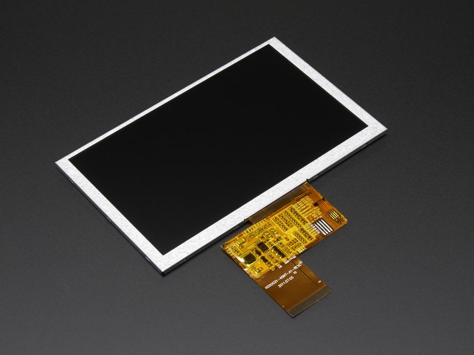
Display ~ $28
Display Driver ~ $30
USB-C Port ~ $2 (for 5 pieces, but you'll only need one)
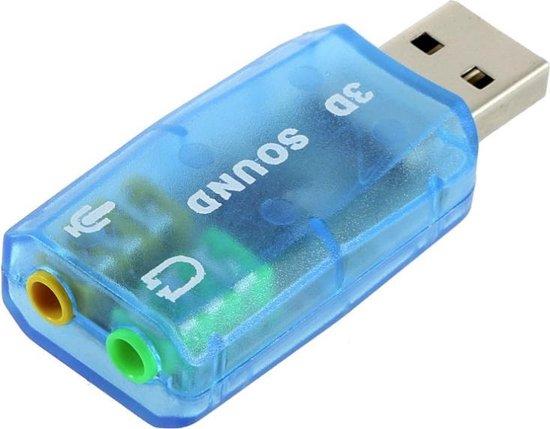
Audio AMP ~ $2
Speakers ~ $3
Screws ~ $2
Capacitor
Wire
Apart from the materials for the build I used the following tools:
Soldering Iron.
Screwdriver.
3D printer.
Hot-glue gun.
If any of the links I provided above don't work you can use the pictures to find similar parts.
(Display)ing the Possibilities


The most important part of this project was the display. I didn't want the unit to be very big, since that would defeat the purpose. So while looking through my box with displays I found a 5-inch 40-pin TTL display I had lying around and that just felt like the right size.
The display section consists of 2 sides, a top and a bottom half. The display unit is sandwiched in between these two halves to keep it safe and secure. The back half has a slit cut out of it for the display ribbon cable to pass through. One thing to keep note of is any components soldered on the ribbon cable. You don't want these to be under tension as that may lead to the solder pads ripping off, breaking the display. The cable bends right above the soldered-on parts and makes an arc to the driver board below them.
The display fits neatly in the two halves and is screwed together. I've modeled one-half of a hinge in the top part of the screen. This hinge will connect the display to the body of the monitor. I designed the hinge to have a friction fit. This way the more you tighten the screw the more friction will keep the display in place.
The (Body) of the Beast


With the display construction looking good I moved on to the part that would bind it all together. This was a little more complex. The body needed multiple cutouts. Had a large amount of overhang and the display driver board needed to be mounted in the correct place based on the ribbon cable. Mounting the driver board was the most important part of the whole so that's where I started.
First I want to thank Adafruit for their superb documentation. Without it, this part would have been a lot more difficult. How did that documentation come into play? Well, they did not only show me the correct location for the mounting holes but also how far the center of the ribbon cable connector was from the edge. I measured how far the edge of the ribbon cable was from the edge of the display, and how wide the ribbon cable was. With this information, I could position the driver board in the right place, first time.
Little side tangent. This was the reason I 3D modeled the entire project in one part. By doing this I was able to easily measure and place components relative to each other. Since they were all in the same part, I could easily reference them against one another.
With the display diver board in the right location, it was only a matter of leaving enough room for the other electronics and making cut-outs for the ports in the right location. I left some room for the speakers at the front and added the required standoffs for the bottom cover. The USB-C port is connected to a USB to 3.5mm jack adapter and the headphone jack of the adapter feeds into the audio AMP that drives the speakers. I chose USB audio because I wanted compatibility with the greatest amount of devices, and not all devices have a 3.5mm jack nowadays. A nifty thing about the audio AMP is that it works with 2.4-5v input. Because of this, I can power the AMP with the spare 3.3V out on the display driver.
As you can see, I've used a lot of hot glue. This is because the parts apart from the display driver board didn't have any mounting holes. Yes, I could have made mounting brackets for each part, like I did with the USB breakout. I didn't because I didn't think it was worth the effort and the port actually needed it so it would stay in place when plugging in the USB cable.
It All Comes Together


With everything wired up, the last thing to do is print the front grill and bottom panel. This panel is there to hide the speakers and give the monitor a nice accent color.
It isn't a perfect solution. I would like to add a 3.5mm jack for audio and be able to switch to it when I want to. There are a lot of small details I would like to improve, like the screw posts for the bottom lid being too short and my original speak choice not fitting. Furthermore, I would like to make a PCB to mount all the electronics on or have mounting places for them. I would like to have a VGA input for better compatibility. I would also like to improve the cable management so it looks as pretty on the inside as it does on the outside. Next iteration I might add a touchscreen, USB hub, and higher resolution screen so this becomes a one-stop shop for interfacing with the connected device. But that'll be a project for future me.
Now if I need a monitor for a server or Raspberry Pi I have to plug in 2 cables and I'm set to go! I hope you enjoyed the guide and that it inspired you to solve a problem you're dealing with.
If you're interested in the 3D model, I've uploaded them here and on GrabCAD. I want to state that this 3D model is not to just be printed (hence why I didn't upload them on Thingiverse or Printables). It only serves as inspiration for your version.
Thank you for reading and if you're interested in some of my other work follow me on Instagram.
@tjdetlev
https://www.instagram.com/tjdetlev/