I Recycled Components and Built a Battery Charger
by me_Cris in Workshop > Home Improvement
42 Views, 0 Favorites, 0 Comments
I Recycled Components and Built a Battery Charger
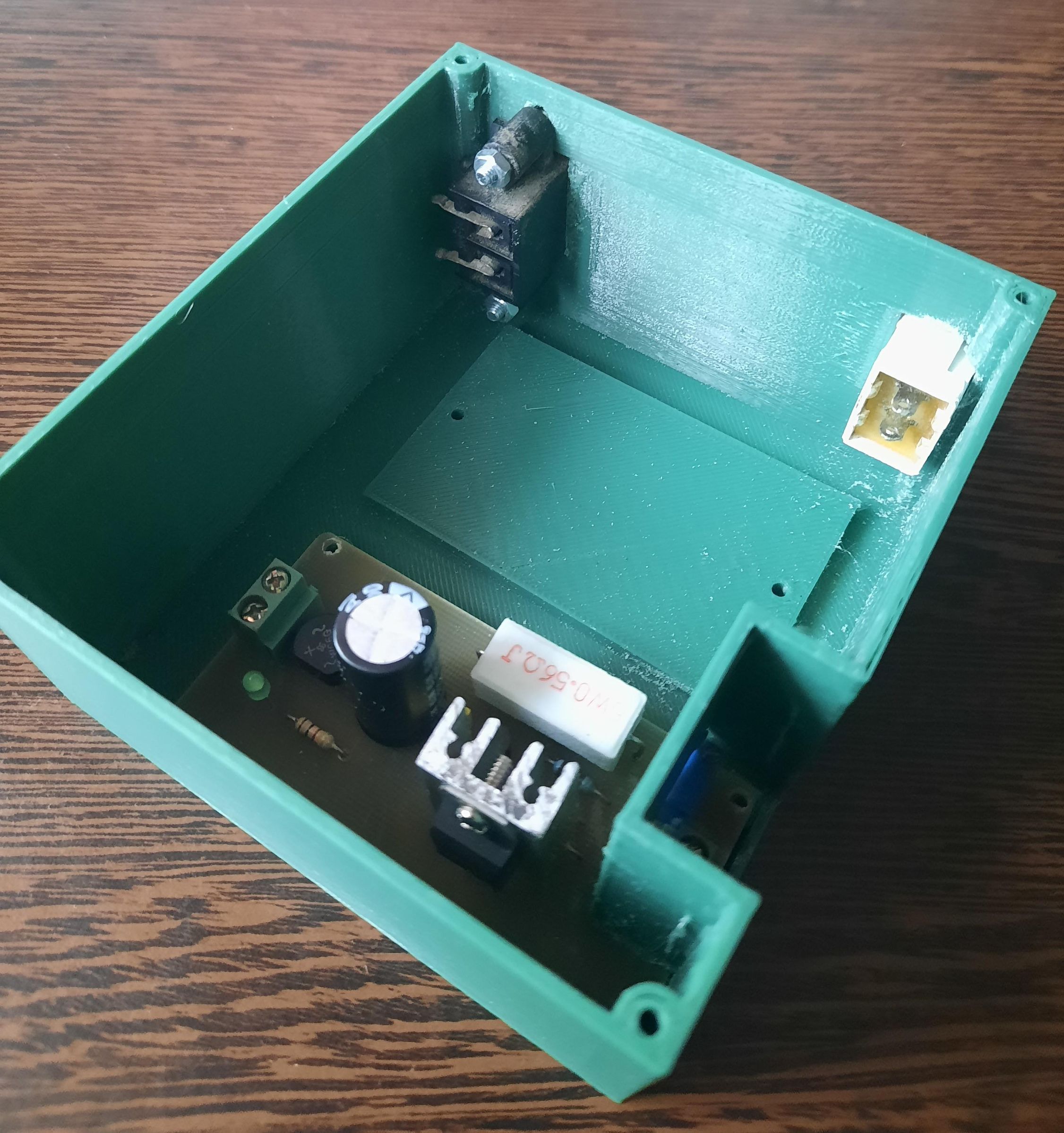
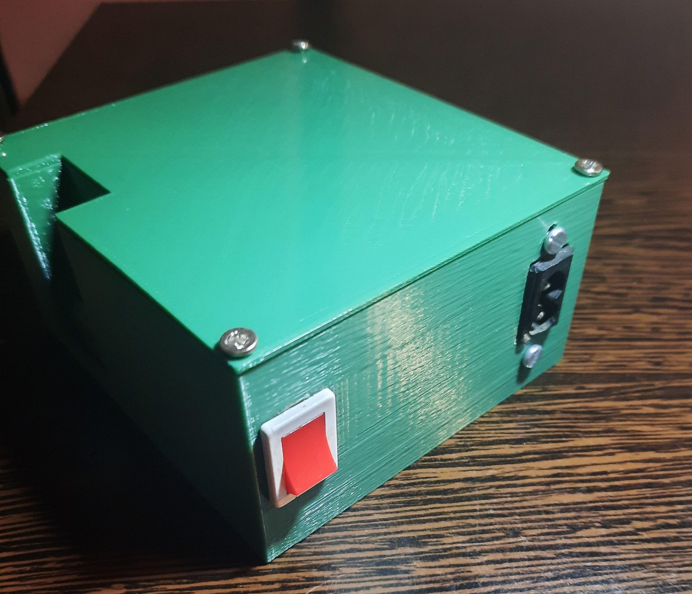
I present to you a project that took a while to reach its final stage. It's been a while since I worked on a project that included a 12V battery (I don't even have that battery anymore 🤣🤣) and I needed a way to charge the battery. I like to spend my time working on something, so I opened the internet, KiCAD and look how I got a PCB. The method of making it - homemade - of course (thermal transfer using a clothes iron); over time, the PCB got worse, it's not perfect, but it still works. What do you think about it?
By the way, this way we also combat e-waste. ✔👏👏
Supplies
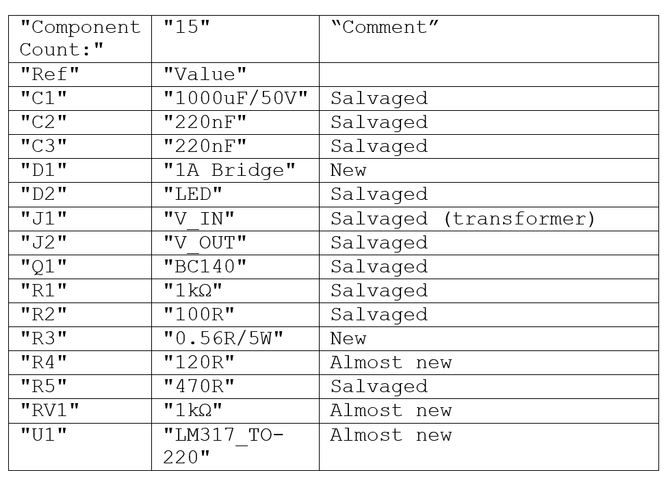
It is a project for which you need to have some tools and materials such as hand tools, drill tools, manual labor of course, and why not a friend, who in my case has a 3D printer.
Circuit Description
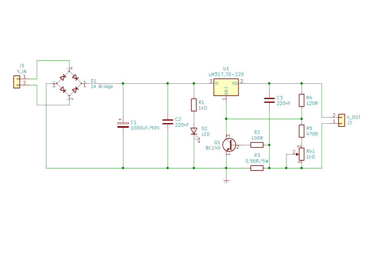
The schematic presented in this project is actually a constant current source to which a current limiting section composed of Q1, R2 and R3 has been added.
The moment the current required for charging is exceeded, it is diverted through Q1 and the output voltage drops. The output voltage is: 1.2x (RV1+R5+R4)/R4 volts. The current limiting occurs when the current is approximately 0.6/R3 amps.
For a 6V battery that requires a faster charge, the charging voltage is 3x2.45=7.35V (3 cells, at 2.45V per cell). So the total value for R5+RV1 is then about 585 Ohms. For a 12V battery the value for R5+RV1 is 1290 Ohms.
For the power supply to work efficiently the input voltage must be at least 3V higher than the output voltage needed to charge the battery.
RV1 is a standard potentiometer capable of handling enough watts for the application in which the circuit is used.
The LM317 must be cooled with a sufficiently large heat sink (ultimately it depends on how much you ask of it).
Except for the situation when the circuit is used for charging car batteries or accumulators, it can also be used as a stabilized voltage source in various applications.
The diode bridge D1 is rated at 2A, and the transformer is a voltage drop from 230Vac, I don't know what voltage it has in the secondary but I trust that I did it correctly.
Most of the components are actually salvaged (I like to reuse what I have), but I also bought a few because I didn't have an equivalent. The transformer is recycled from an old radio, I think it can handle about 1A, it gets a little warm when I connect a more discharged battery (i.e. one that also draws a lot of current). It may not be pretty but for me it is still good to use. I think from of all these components, the transformer is probably the most unsuitable, meaning that putting one from a radio into a charger means some abuse, but I have enough "abused" components being unsoldered and later re-soldered.
Assembly Pictures
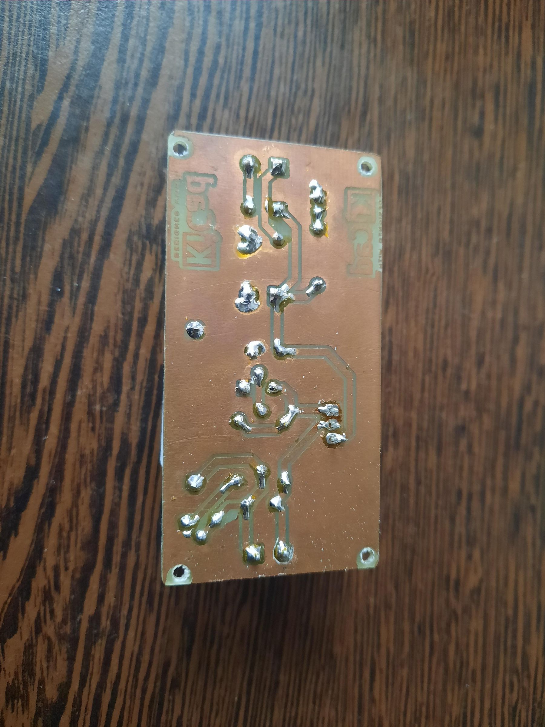
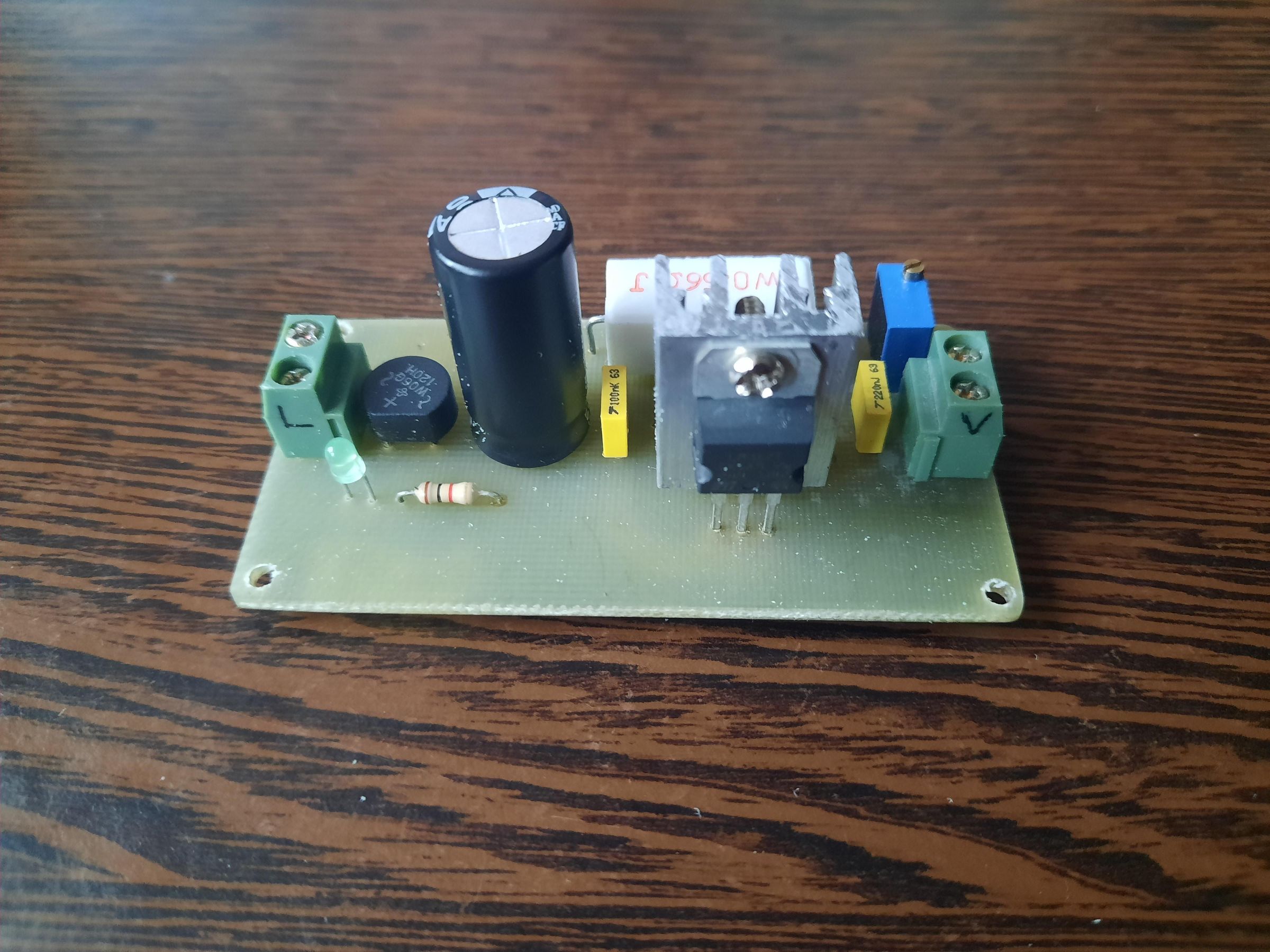
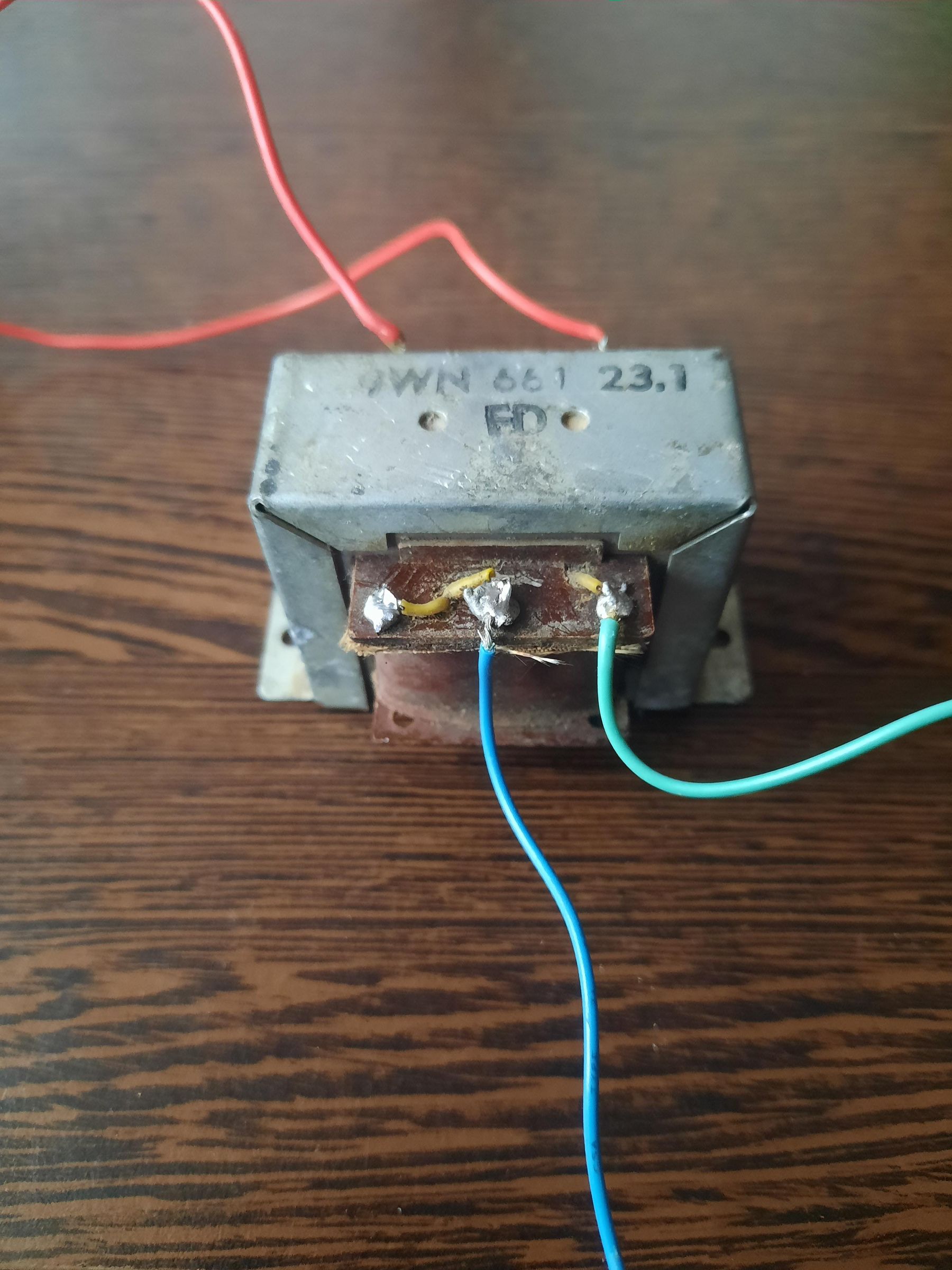
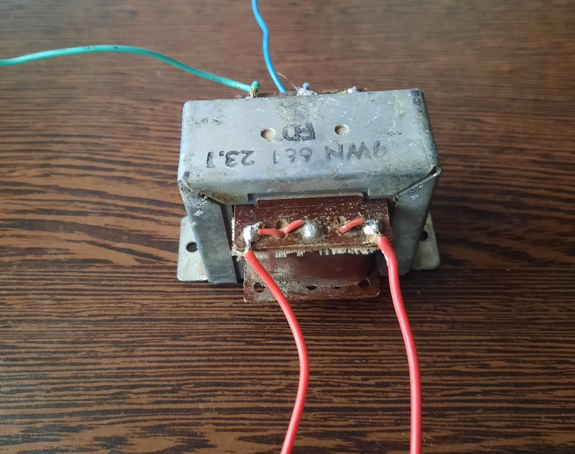
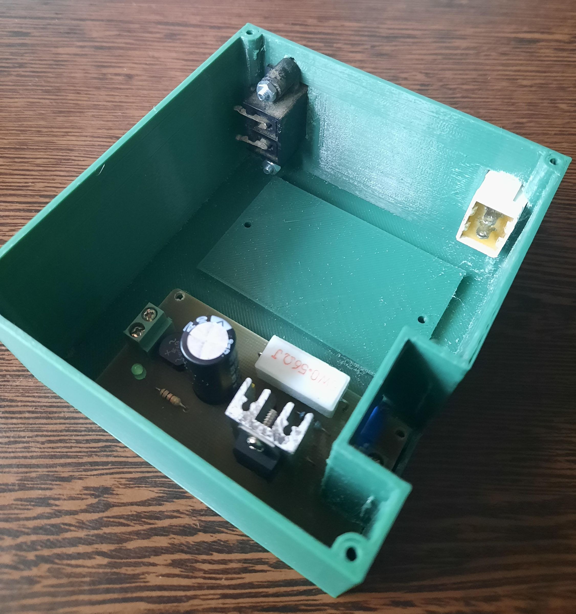
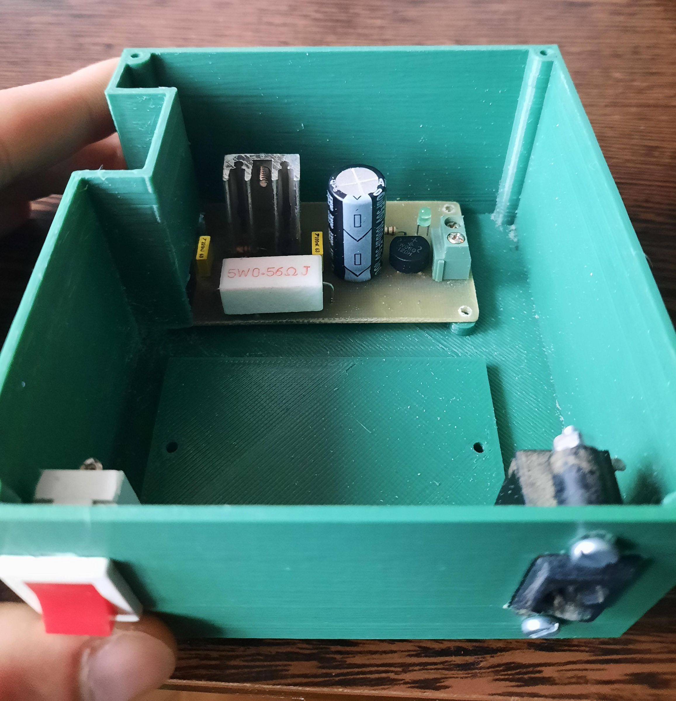
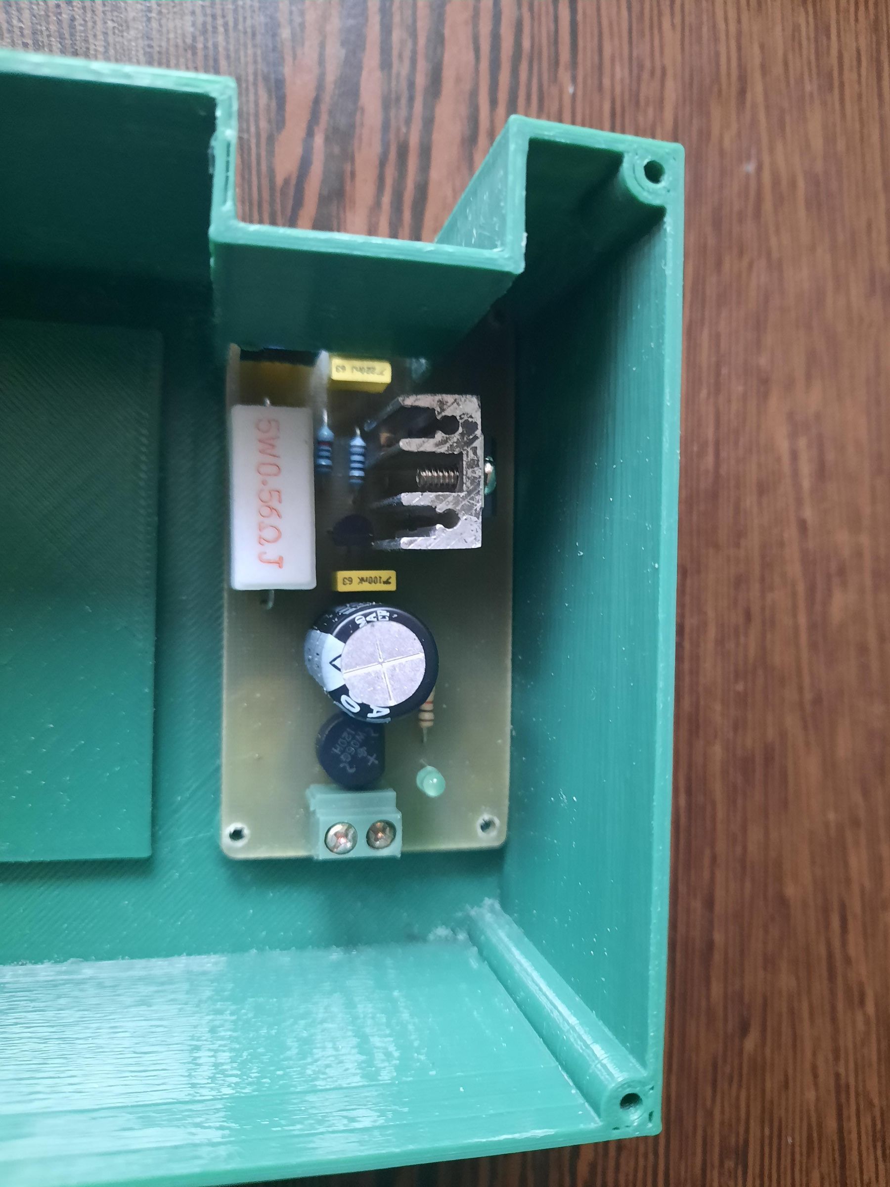
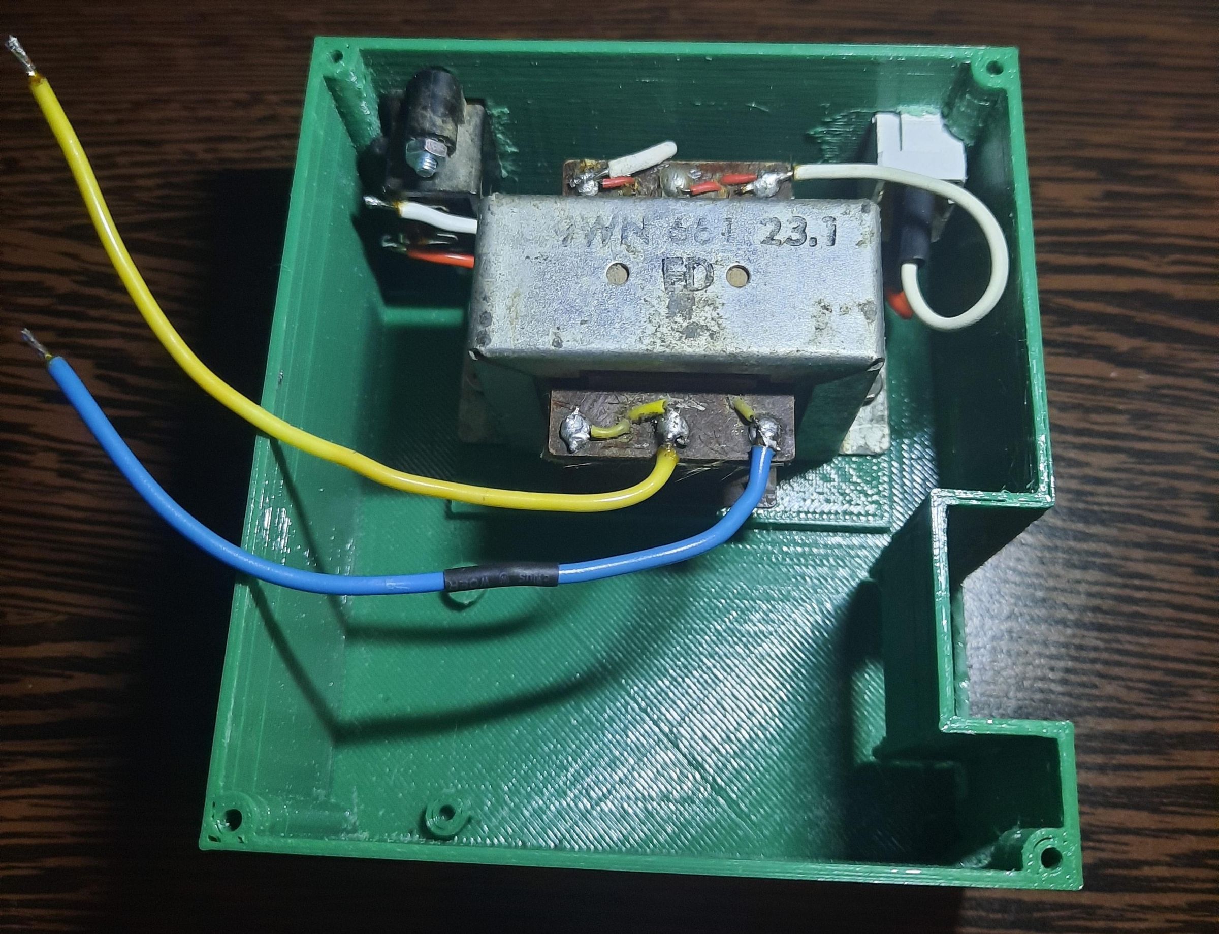
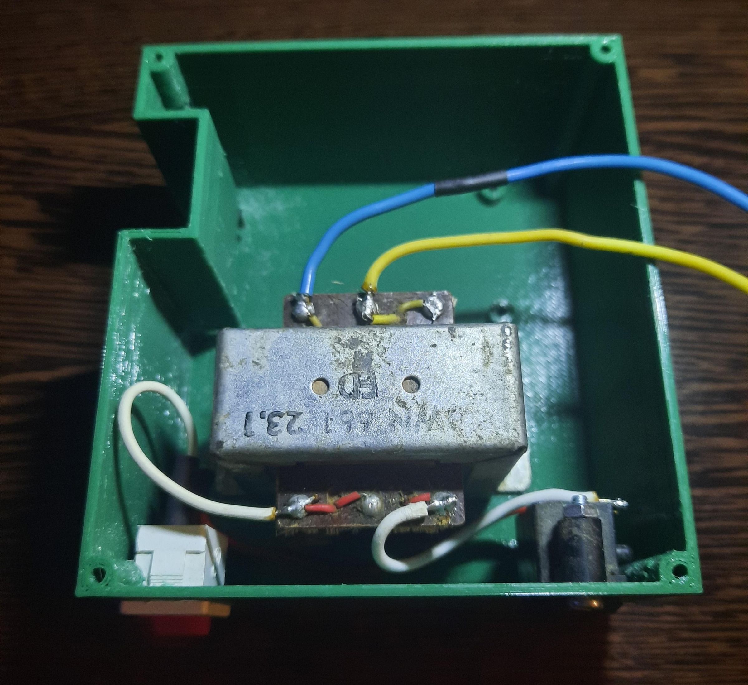
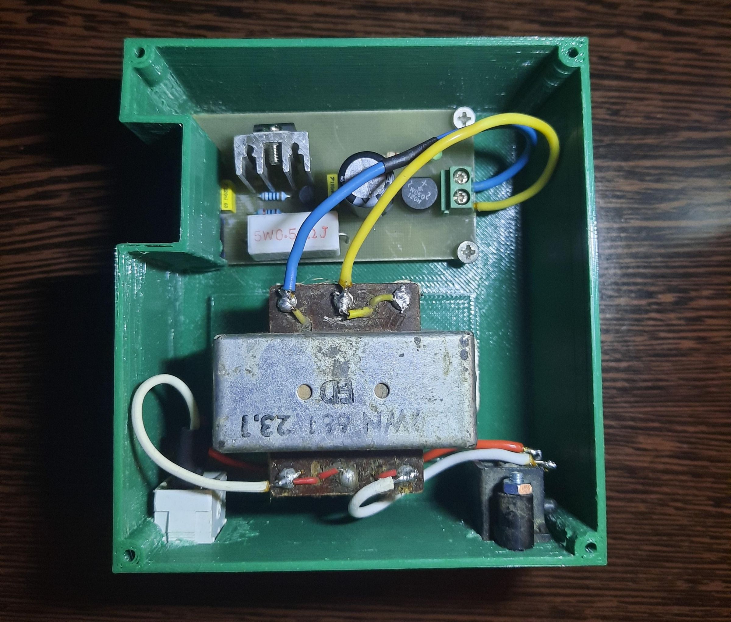
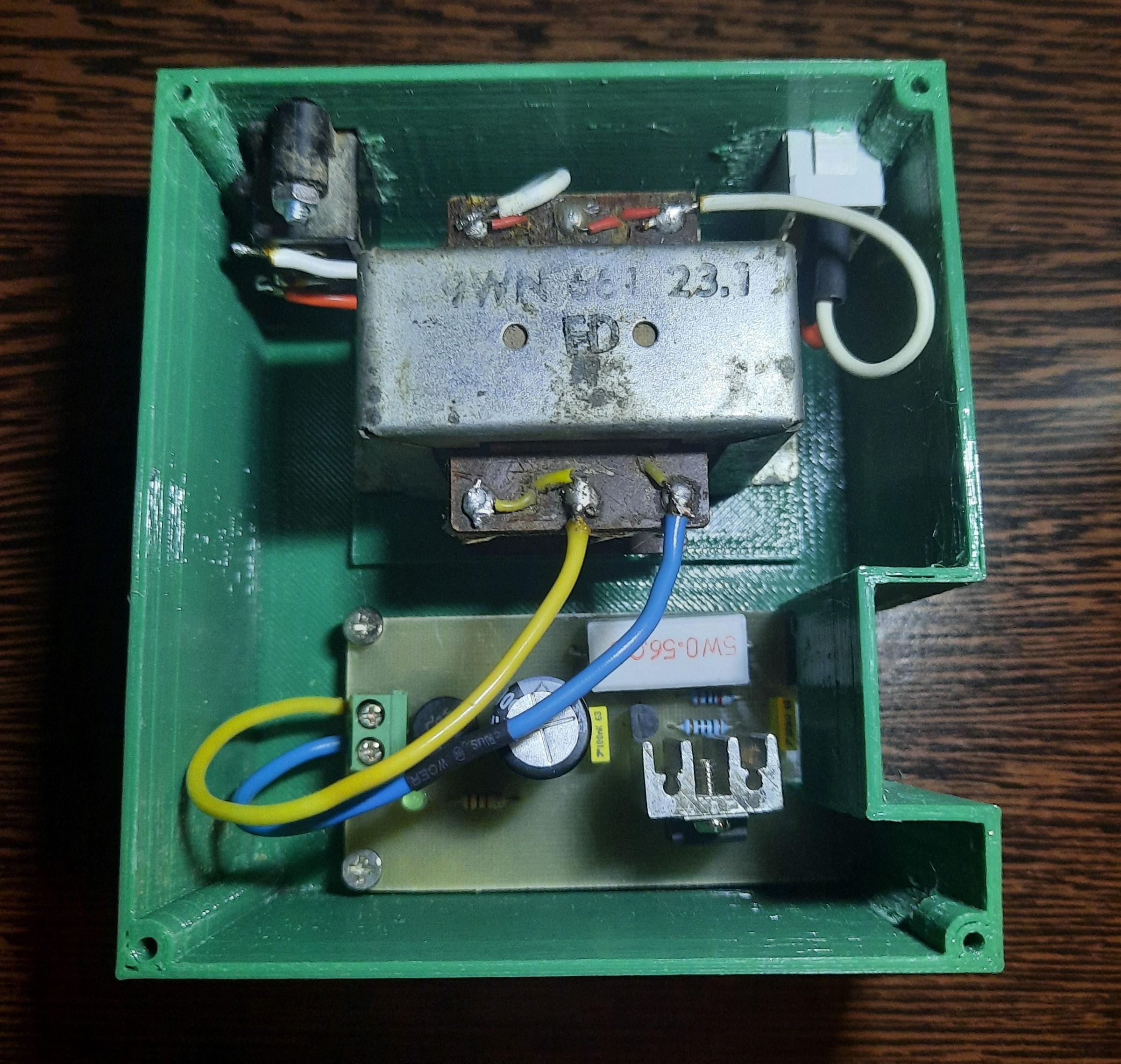
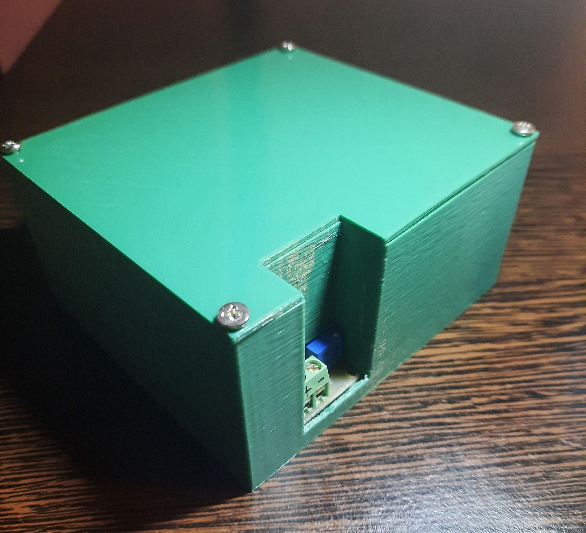
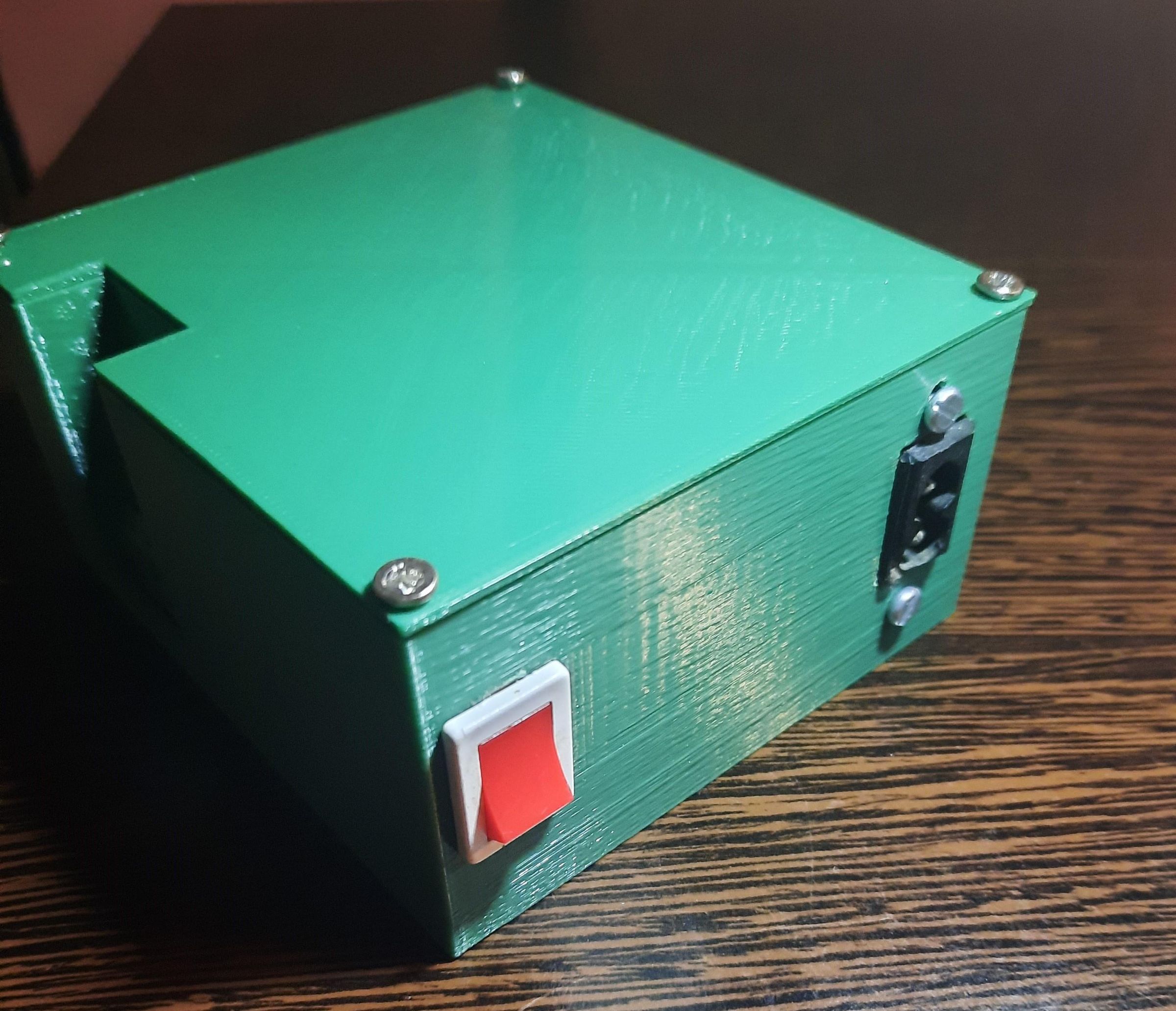
The recent novelty is 3D printing, after some experiments with Tinkercad I made some 3D designs, I went to town to a workshop where they have a 3D printer. It's not perfect, I had to use a file and a letcon to make room for the PCB. I like 3D printing because it allows me to create custom projects.
I soldered a few wires, I couldn't completely insulate them but since the case is plastic I don't worry about touching something that would make me smile too loud. 😆😅