IBrick

Greetings everyone, and welcome back.
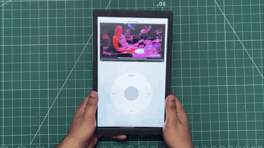
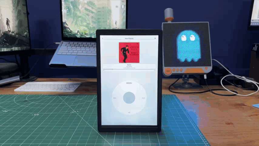
Here's something BIG. Meet iBrick, a giant, 3rd-generation iPod Nano-inspired music player, powered by a Raspberry Pi Compute Module 5.
The 3rd-generation iPod Nano was one of those gadgets I always admired growing up. Its compact form factor, vibrant user interface, and the iconic click wheel made it one of the most recognizable portable music players of its time. Although I never got the chance to own one, the design always stuck with me.
Today, original iPod Nanos are becoming increasingly difficult to find in good condition. Many available units have worn-out batteries, cosmetic damage, or are simply too expensive to justify buying for a project.
Rather than restoring an old device, I decided to recreate the experience but with a giant twist.
At the heart of this build is a Raspberry Pi Compute Module 5 paired with a 10-inch Waveshare touchscreen. Instead of starting from scratch, I repurposed the hardware from my previous Absolute Linux Tablet project, giving it a completely new identity through a redesigned enclosure and custom software.
This Instructables walk-through the entire process of transforming that Linux tablet into a fully functional giant iPod Nano.
Supplies
These were the materials used in this project.
- Raspberry Pi CM5 4GB RAM with Evaluation Board
- NVME SSD (for OS)
- Waveshare 10.1 Inch DSI display for Raspberry Pi
- Power Management Circuit (Salvaged from Powerbank)
- LiPo cell 3.7V 10000mAh (Salvaged from power bank)
- 3D Printed Parts
- SPEAKER 4Ohms
- MAX98357A I2S Audio Amplifier
- M2 screws
IPOD 3rd GENERATION
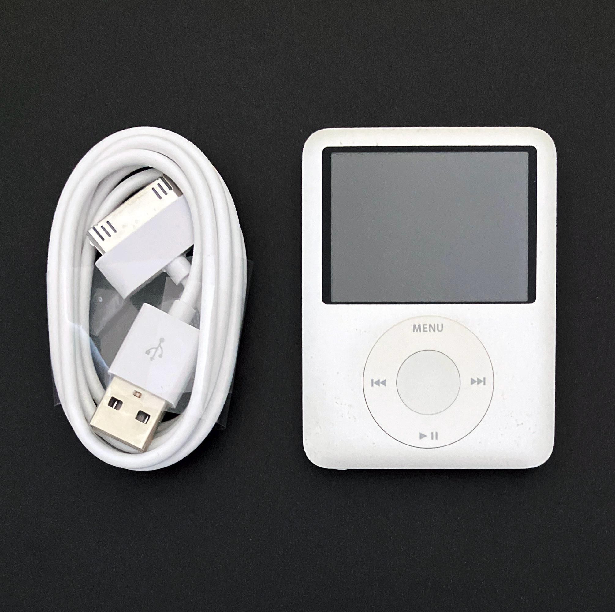
Released in 2007, the 3rd-generation iPod Nano marked a significant departure from its predecessors. Nicknamed the "fat Nano" due to its shorter and wider design, it featured a 2-inch QVGA color display with a resolution of 320 × 240 pixels, making it ideal for both music and video playback.
The device retained Apple's iconic Click Wheel, a touch-sensitive circular controller that combined rotational scrolling with five physical buttons, allowing users to navigate menus quickly with one hand. Available in 4 GB and 8 GB flash storage variants, the iPod Nano could store thousands of songs and supported popular audio formats such as MP3, AAC, WAV, AIFF, and Apple Lossless, along with H.264 and MPEG-4 video playback.
Powered by a rechargeable lithium-ion battery, Apple rated it for up to 24 hours of music playback and around 5 hours of video playback on a single charge. Its compact aluminum enclosure, bright display, and intuitive user interface made it one of the most recognizable portable media players of its era.
HARDWARE - RASPBERRY PI CM5
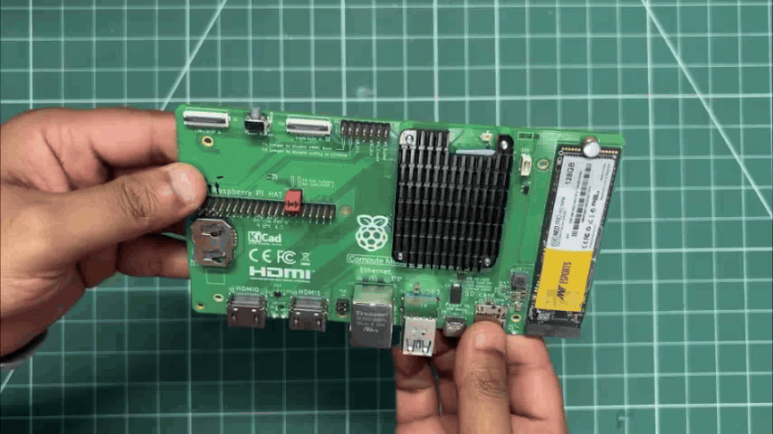
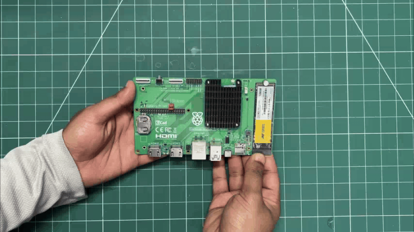
The brain of our project is the Raspberry Pi CM5, which is a more industrial-oriented version of the usual Raspberry Pi 5 in a module form factor. It uses the same Broadcom BCM2712 quad-core 64-bit Arm Cortex-A76 (Armv8) SoC running at 2.4 GHz, but in a much more compact package.
The CM5 sits on an evaluation board that breaks out USB ports, Ethernet, dual HDMI ports, GPIO headers, an SD card slot, and even an M.2 port for adding an NVMe SSD.
Here, we are using the 4GB variant, which comes with onboard 32GB eMMC storage.
For the operating system, I used the new Raspberry Pi OS based on Debian Trixie. The OS is installed on an NVMe SSD, which makes the system super fast. OS installation was done using Raspberry Pi Imager. We connected the SSD using an M.2-to-USB adapter and flashed the operating system directly onto the NVMe drive. Once the NVMe SSD was plugged into the CM5 board, the system booted directly from the SSD.
HARDWARE- WAVSHARE 10.1 INCH DSI SCREEN

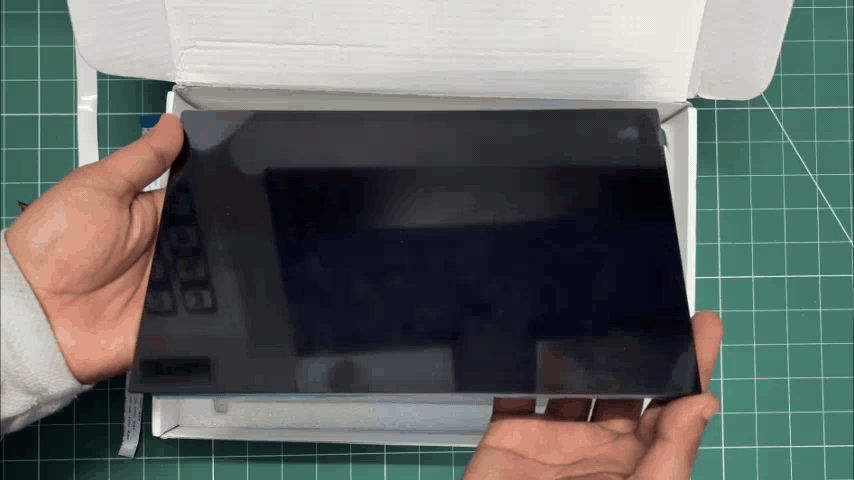
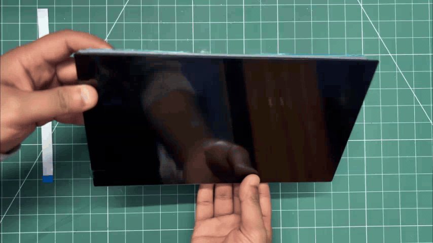
For the main display, I wanted something huge, not the average 7-inch size, but something larger.
Connectivity was also an important factor, as I wanted a DSI interface instead of HDMI.
So, I selected Waveshare's 10.1-DSI-TOUCH-A display for this project. It is a portrait touchscreen LCD display with ten-point capacitive touch control. The display uses an IPS panel with a hardware resolution of 800×1280, which is perfect for our tablet application.
The LCD pairs with the Raspberry Pi through the DSI interface and supports a refresh rate of up to 60 Hz, which is more than enough for this application.
The kit comes with two FFC cables for pairing the display with a Raspberry Pi 5 or CM5, one FFC cable for pairing with a Raspberry Pi 4, a power cable, and a couple of PCB standoffs.
You can check out more about this display from its wiki page.
https://www.waveshare.com/10.1-dsi-touch-a.htm?&aff_id=Arnov
WAVESHARE SERVICE
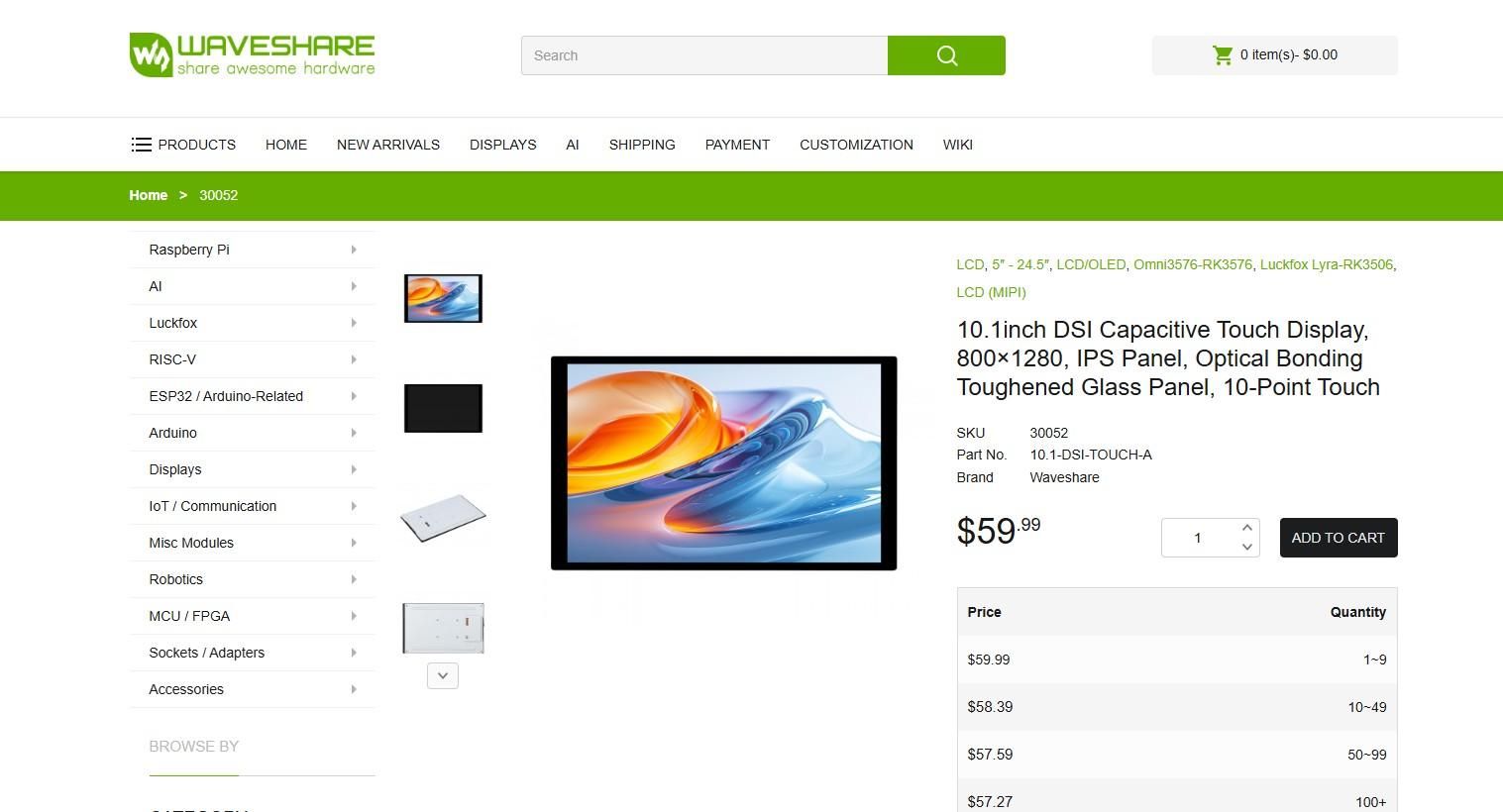
Special thanks to Waveshare for providing the hardware used in this project. The 10.1 Inch DSI screen and supporting accessories were supplied as review units for testing and evaluation.
Waveshare is a leading global provider of electronic components, modules, and development tools used across robotics, IoT, automation, education, and many other fields. With a strong focus on quality, reliability, and continuous innovation, Waveshare has earned the trust of engineers, designers, hobbyists, and makers worldwide.
Their extensive product lineup, from displays and HATs to expansion boards and embedded modules, makes them a go-to choice for both professional builds and DIY projects.
POWER SOURCE- SMARTPHONE PD CHARGER
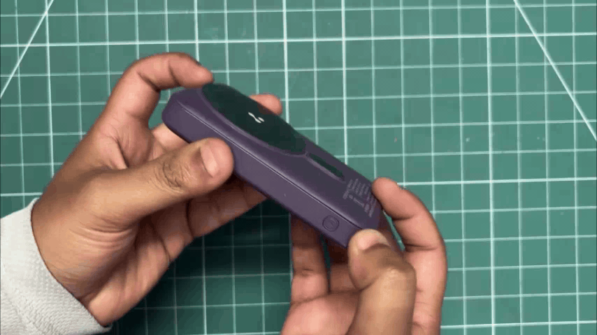
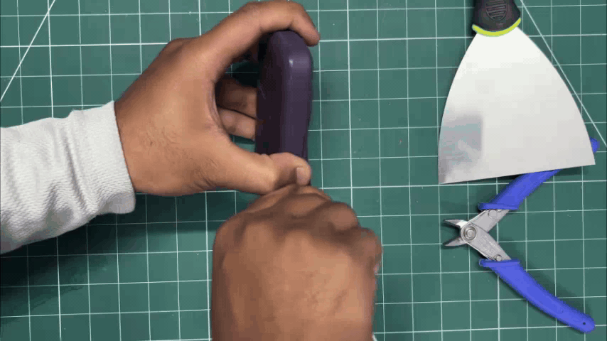
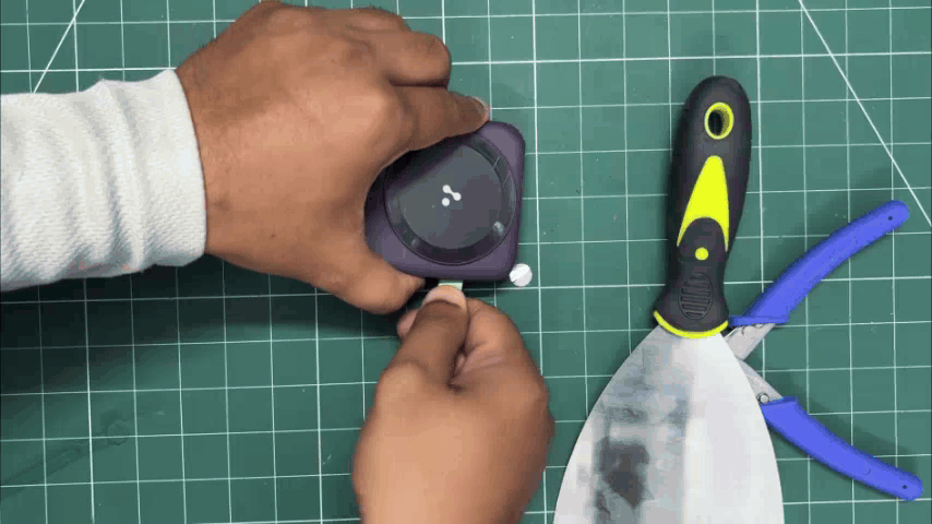
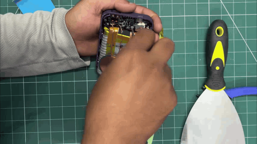
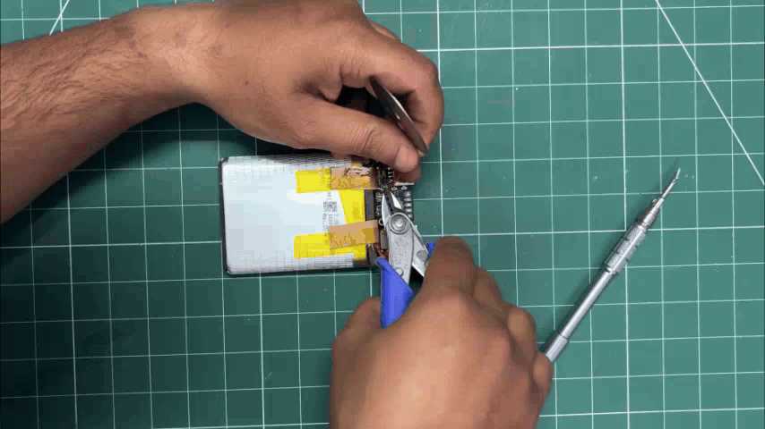
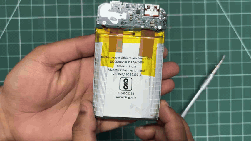
For the power source of the tablet, one of the best options is to harvest the power circuit and lithium cell from a power bank. Here, I used a PD power bank that I normally use for charging my iPhone and other devices. It can provide both power input and power output through its USB Type-C port, along with a stable 5V 3A output from its USB port.
- Using a prying tool, we started opening the power bank. I didn't have a proper pry tool available, so I used the back side of a pair of tweezers.
- By inserting it along the seam of the enclosure and applying a bit of pressure, the two halves of the body started separating.
- The enclosure was held together using snap locks, so once we created an opening on one side, we inserted our pry tool into the gap and moved it along the edge to completely remove the lid.
- Doing that completely separated both parts. The circuit was secured in place with M1.8 screws, which we removed.
- The battery was also secured with adhesive tape, so by applying a little pressure, it came off as well.
- This was a MagSafe charger, so it also included a charging coil, which we removed from the circuit.
As a result of this harvesting process, we ended up with a 10, 000mAh battery and a power circuit capable of powering our display and Raspberry Pi setup.
POWER SOURCE ASSEMBLY
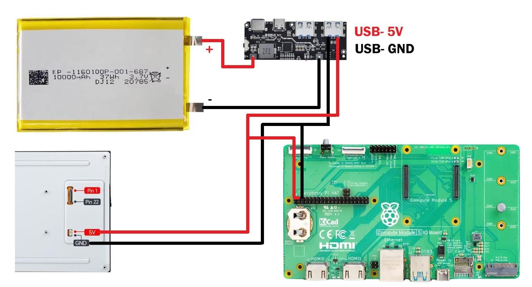
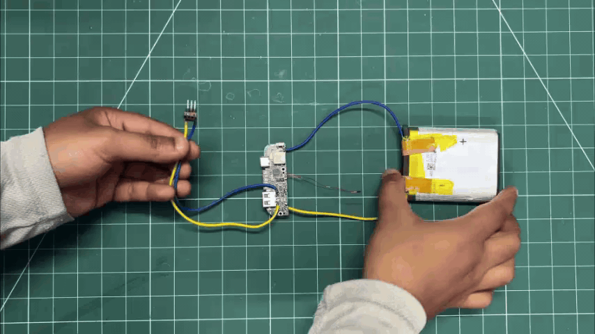
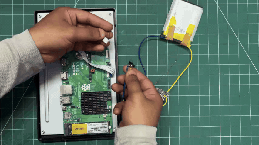
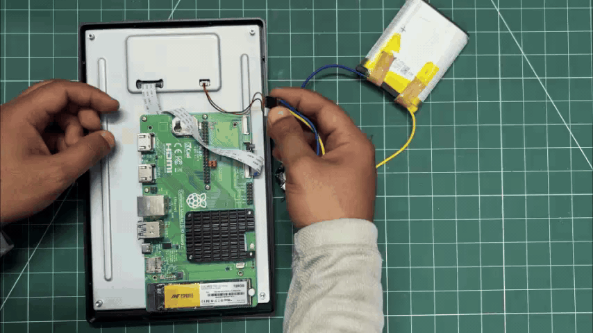
- After harvesting the lithium-polymer cell and charger circuit from the power bank, we extended the battery wires by desoldering the original wires and replacing them with longer ones.
- We connected the battery positive terminal to the B+ pad on the circuit and the battery negative terminal to the B- pad.
- Next, we soldered two output wires to the USB port's 5V and GND terminals. For connecting these output wires to the Raspberry Pi header pins, we added a CON3 female header connector to the 5V and GND wires.
- With this header connector, we can simply plug it onto the Raspberry Pi's GPIO header 5V and GND pins, which power the entire setup.
IPOD UI
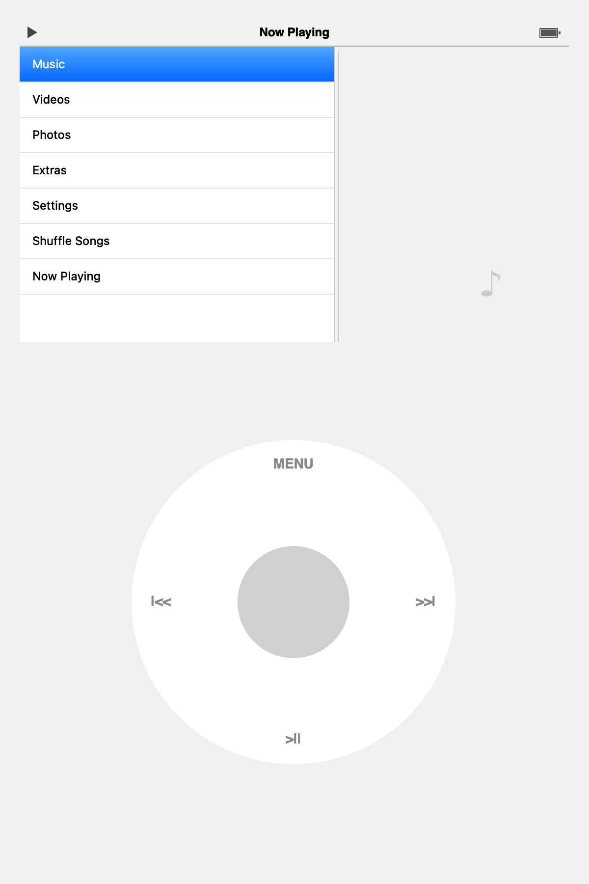
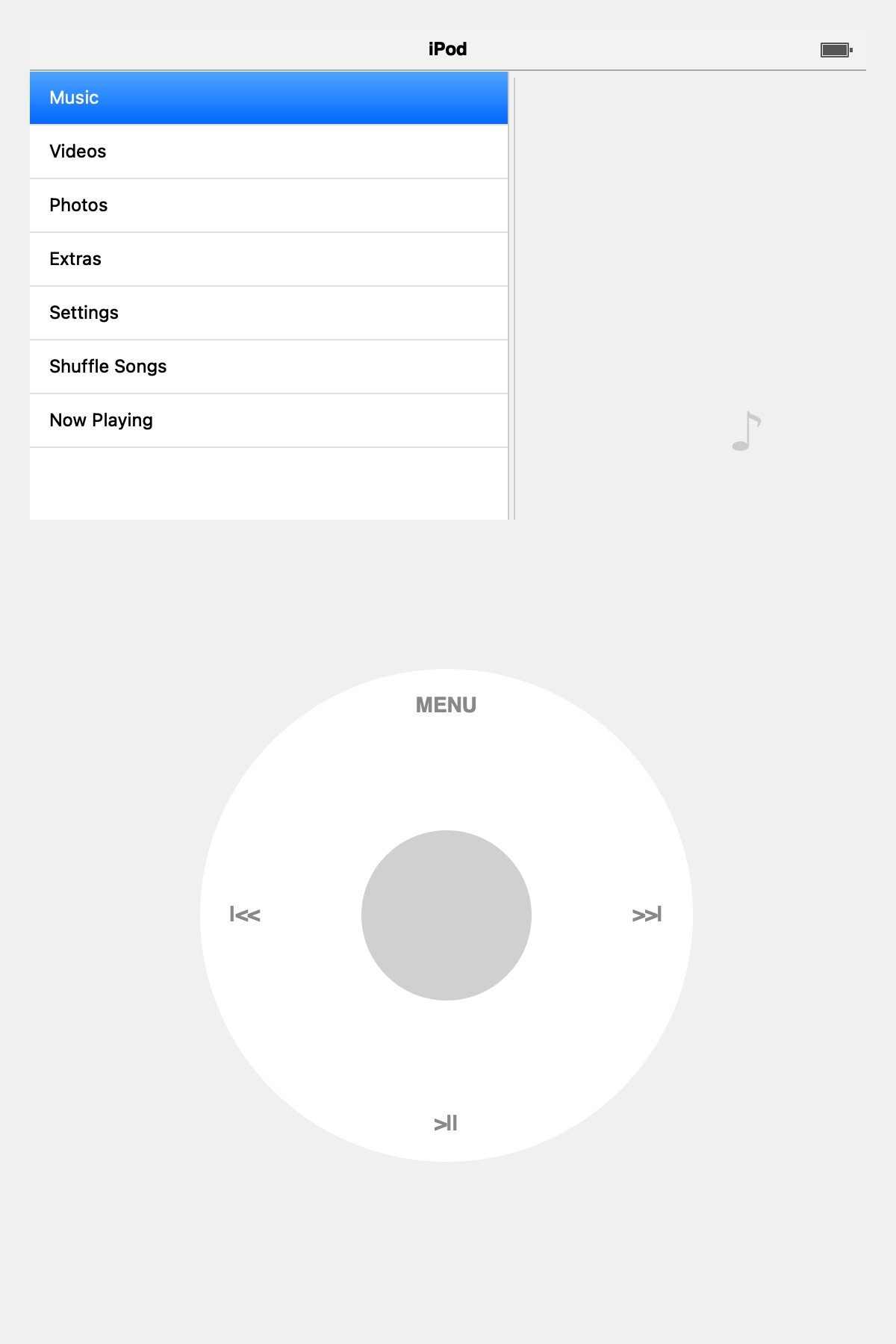
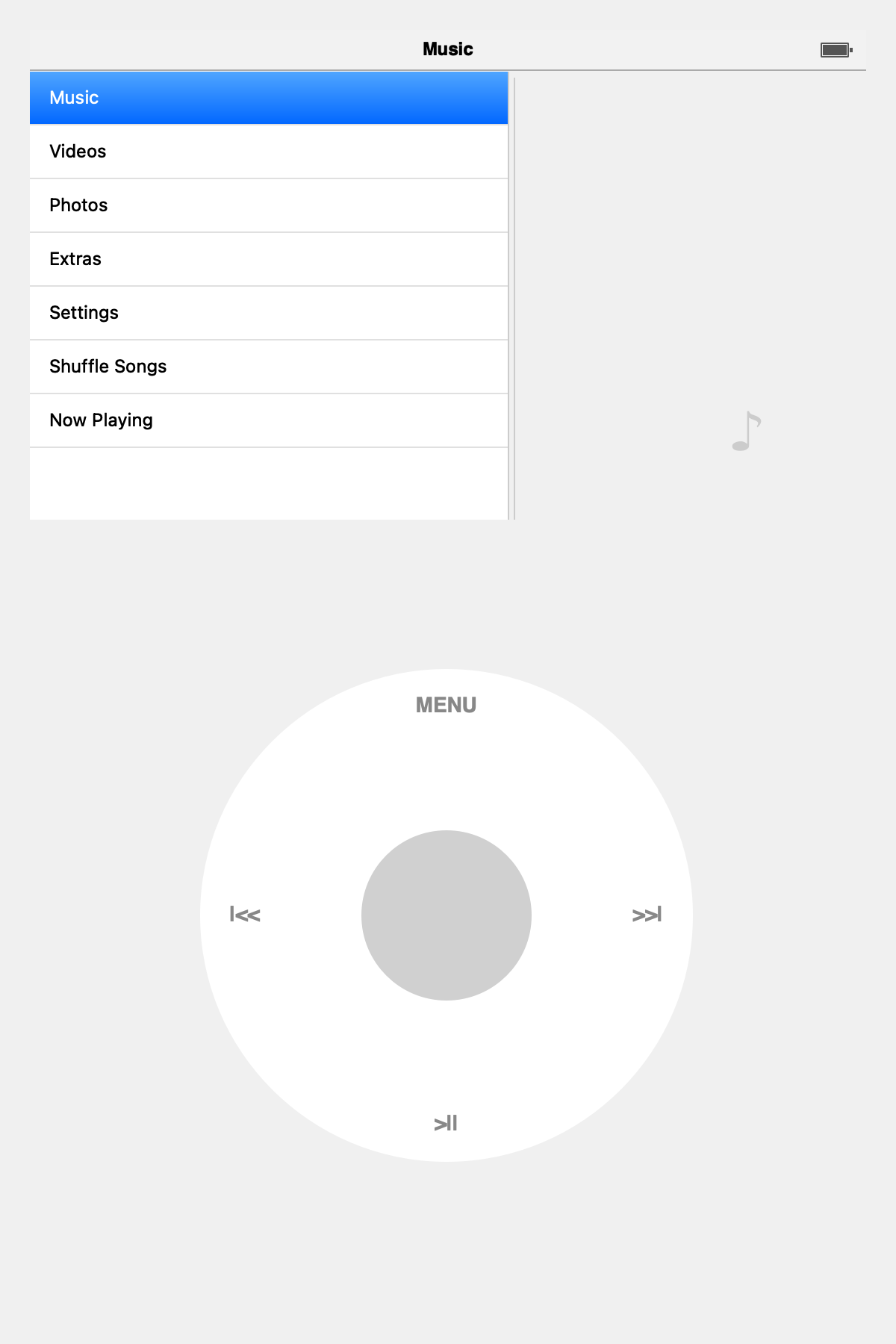
The software and UI for this project were developed with the help of my friend Aahan Sharma, who handled the application development. You can find his GitHub repository linked below.
https://github.com/AahanDoesGit/iPod-classic-Cm5
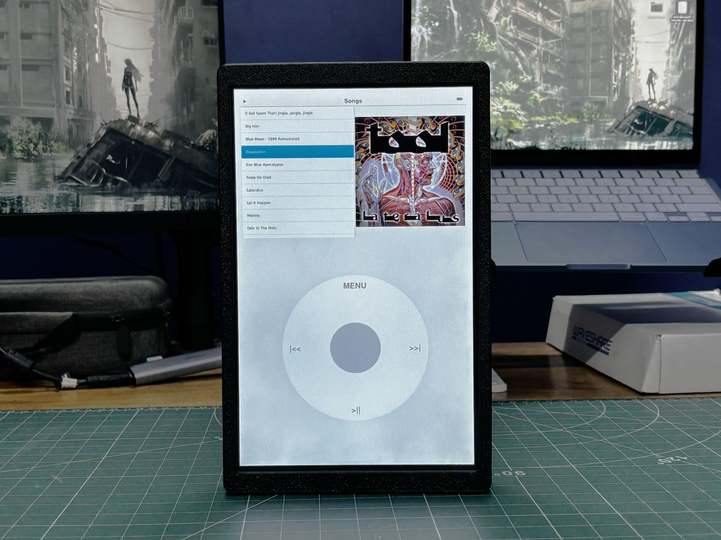
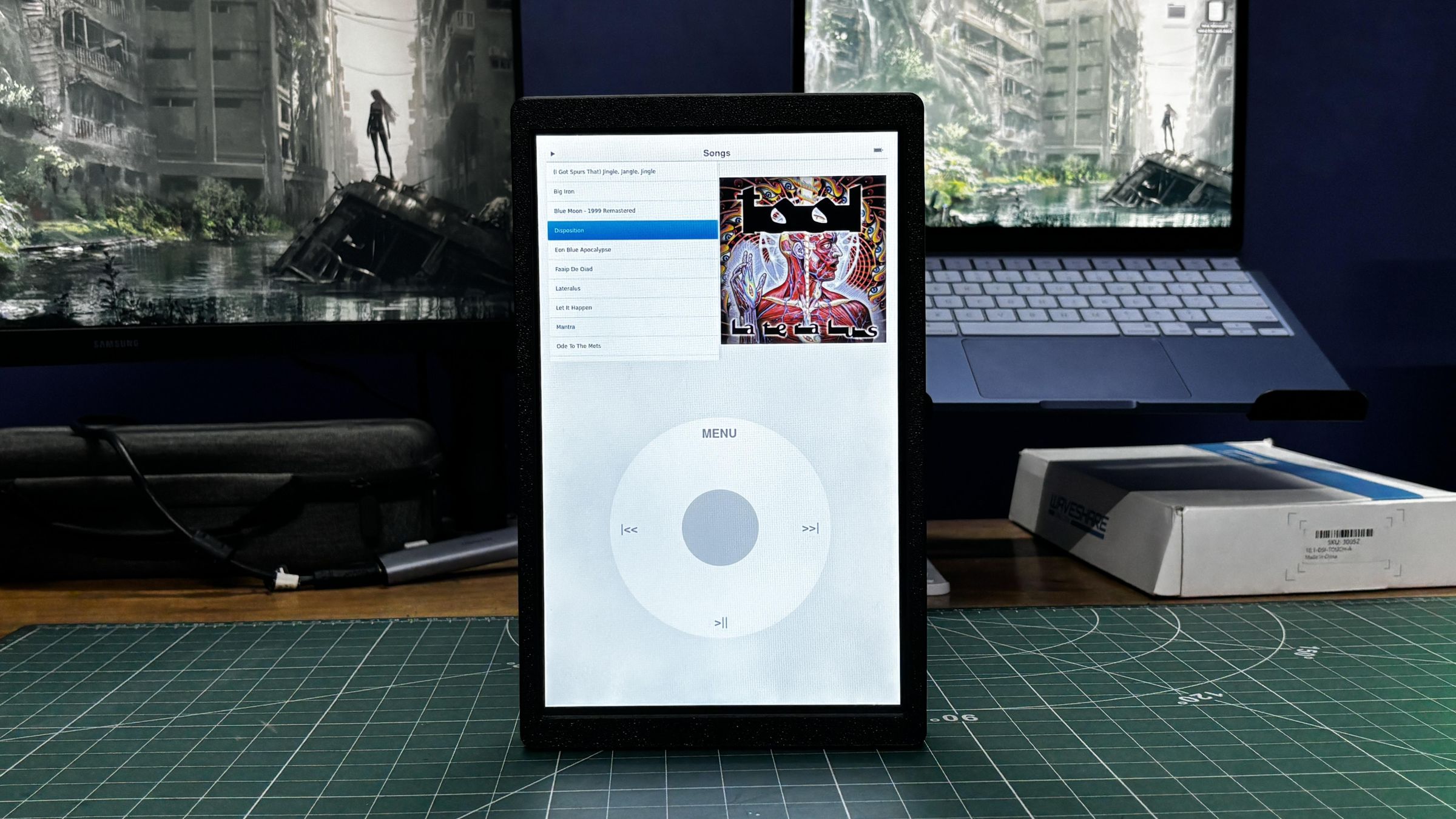
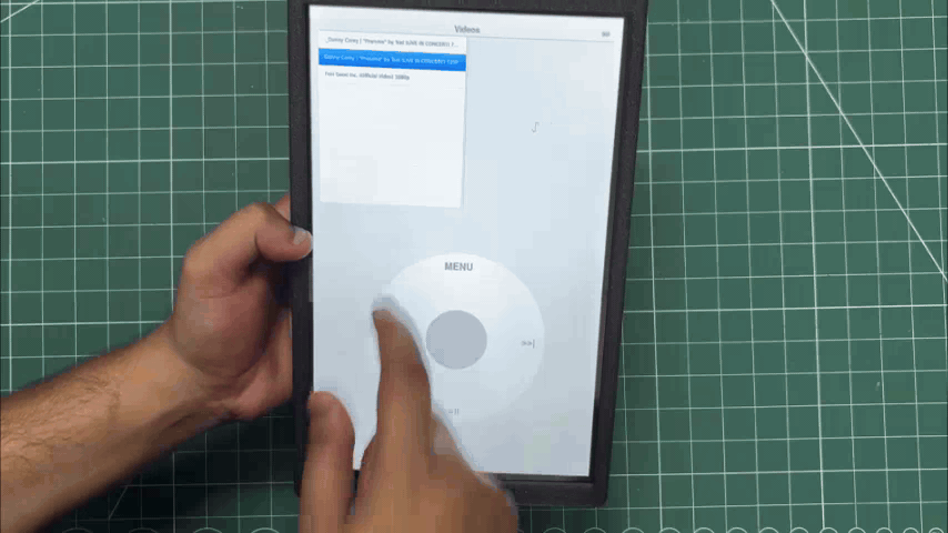
The goal was to recreate the feel of the original iPod experience as closely as possible. The interface features authentic sliding stack navigation, where nested menus animate left and right just like the original firmware, along with a fully emulated click wheel supporting rotational scrolling and the classic five-button controls. The media library is scanned in the background using Mutagen, automatically detecting newly added MP3 files, while python-vlc provides hardware-accelerated audio and video playback for smooth, low-latency performance.
The codebase is organized into three main sections: the core logic (library.py and player.py), the UI components (iPod_screen.py, now_playing.py, sliding_stack.py, and click_wheel.py), and the main application entry point (main.py), making the project modular and easy to extend.
Main Application and Background Thread
In 'main.py ', we initialise the Qt application and set up our primary UI elements: the top screen and the bottom click wheel. 'QThread' runs continuously in the background to scan the 'music/' folder for changes without freezing the UI.
Sliding Nav Menu
The core of the iPod experience is the sliding menus. We built a custom 'SlidingStackWidget' 'ui/sliding_stack.py' that uses Qt 'QPropertyAnimation' to smoothly slide 'QWidget' pages in from the left or right when navigating
Screen States and Nav
The 'IPodScreen' 'ui/ipod_screen.py' acts as the state machine for the UI; it pushes and pops different menu lists using a 'menu_history' stack to remember where the user came from.
Audio Playback
We use 'python-vlc' for robust media decoding; found in 'core/player.py' it also handles a fallback for Mac testing via 'afplay '. The player integrates with the 'NowPlayingScreen' to sync progress bars and elapsed times.
Running the App
- Install the dependencies via 'pip'
- Put some '.mp3' files in the 'music/' directory.
- Run the main script.
DESIGN
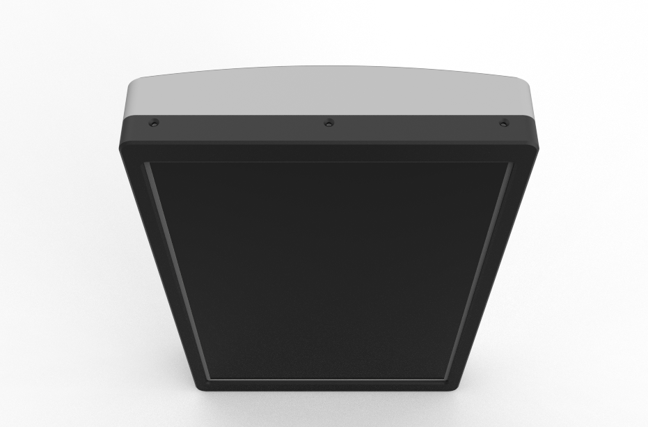
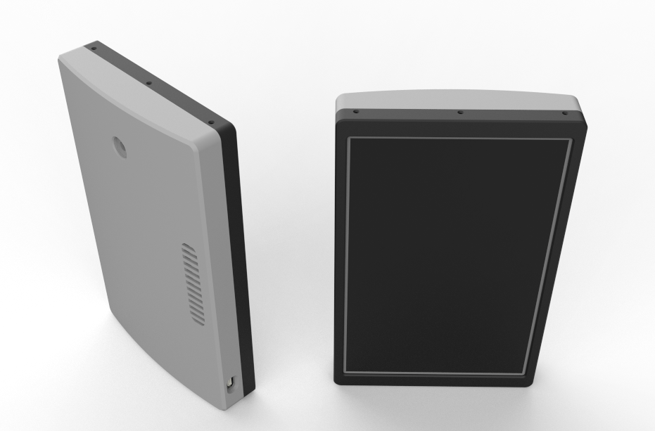
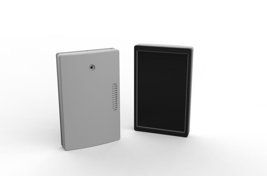
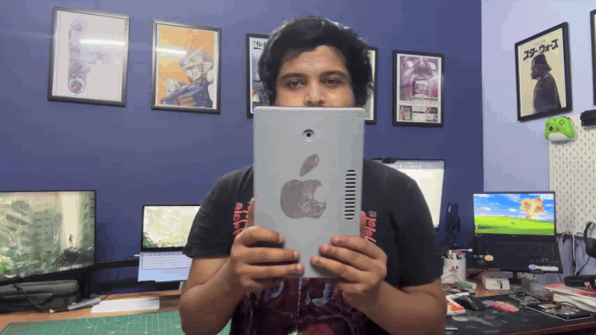
The main design of iBrick follows a simple, boxy form with a slightly curved back enclosure. The overall construction is divided into two primary parts: the front frame and the back enclosure, with the internal hardware, including the display, Raspberry Pi Compute Module 5, power bank, battery, and other electronics, remaining largely unchanged from the original Absolute Linux Tablet.
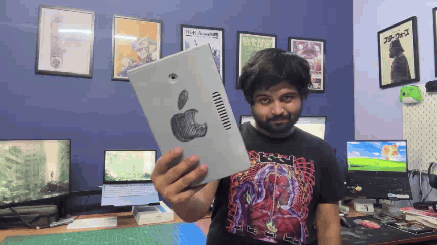
The main redesign was focused on the back enclosure. I intentionally kept it chunky and oversized, giving iBrick its distinctive brick-like appearance, which also inspired the name. The front frame uses a minimal-bezel design to maximize the display area while keeping the overall look clean.
Rather than trying to physically replicate every detail of the original iPod Nano, my goal was to keep the hardware design simple and recreate the recognizable iPod experience primarily through the software UI. Elements such as the classic navigation, click wheel, menus, and animations were therefore implemented digitally, allowing the oversized enclosure to remain simple while the software provides the nostalgic iPod character.
CONSTRUCTION
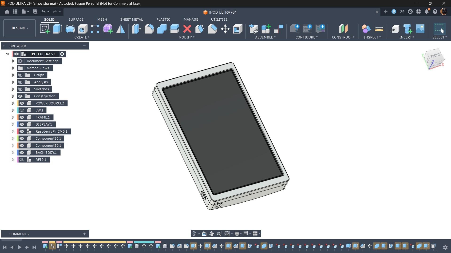
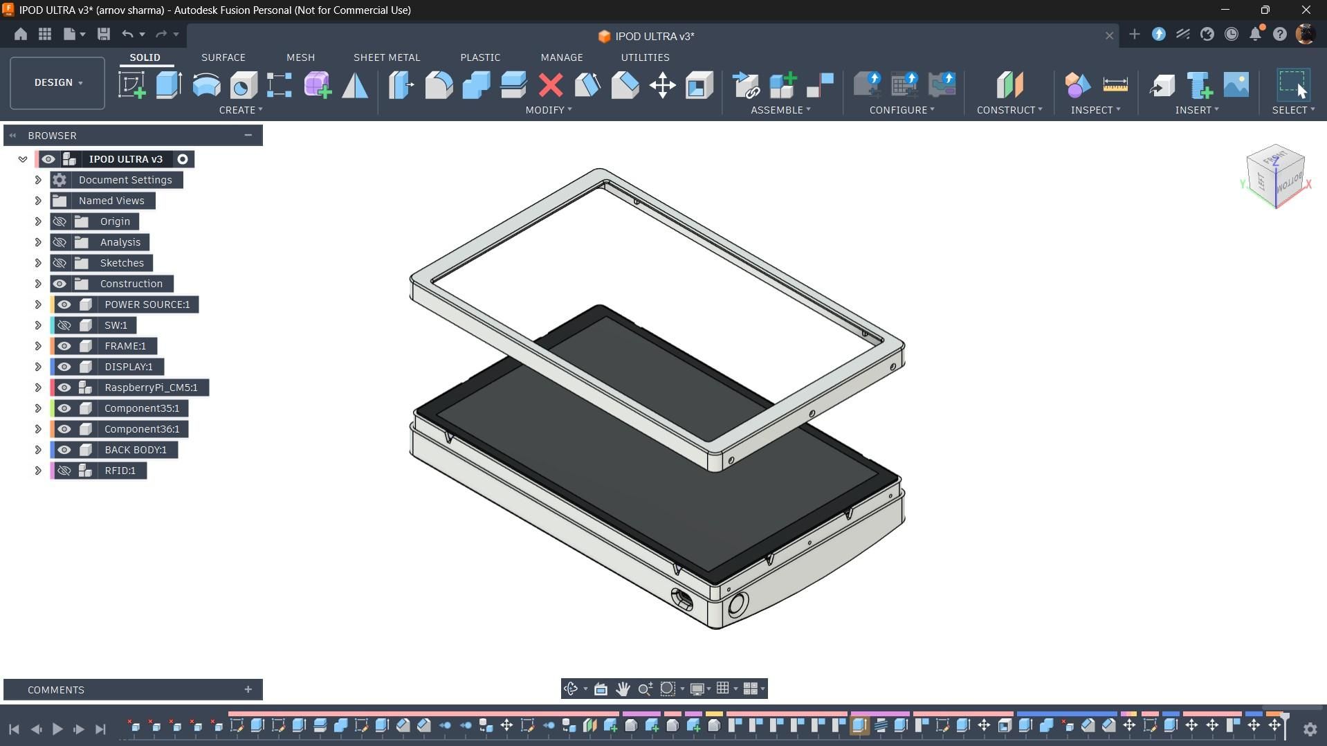
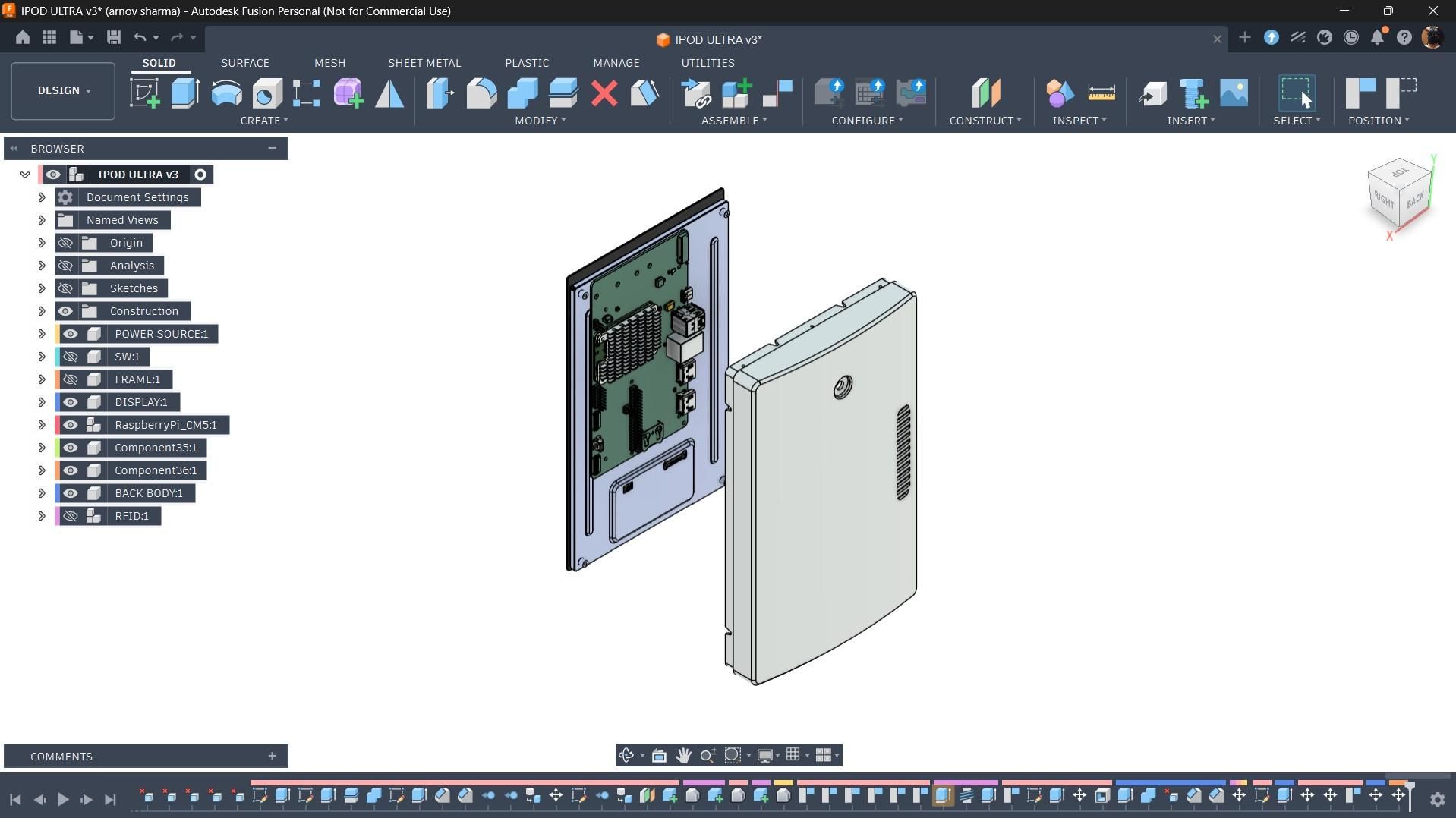
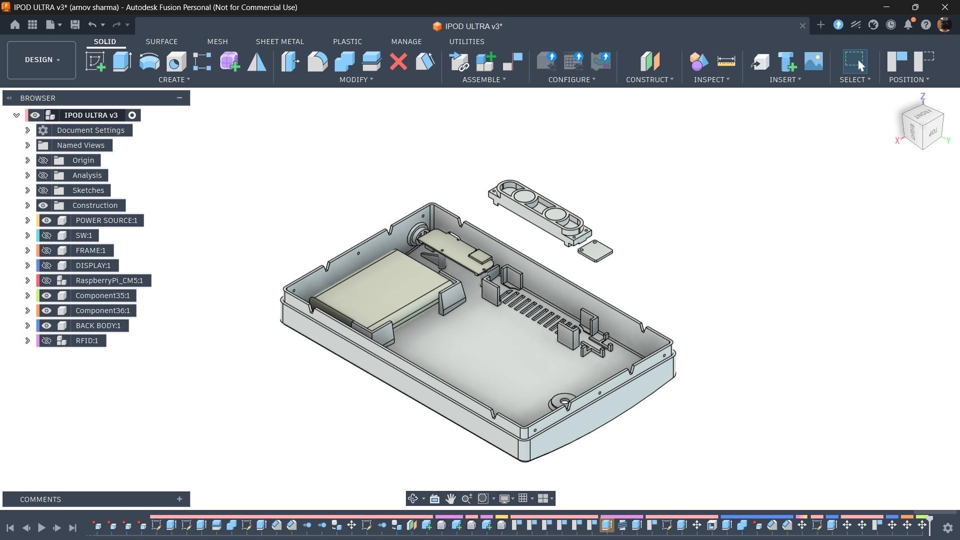
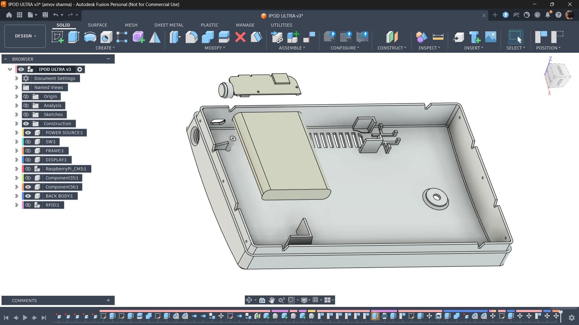
The enclosure mainly consists of two parts: the front frame, which holds the display and Raspberry Pi CM5 assembly in place, and the back enclosure, which houses the battery pack and power circuitry. Both parts are designed to fit together and are secured using M2 screws inserted through mounting holes positioned around the perimeter of the frame.
The back enclosure also includes dedicated mounting features for the speaker and MAX98357A I2S amplifier, allowing both components to be securely positioned inside the enclosure.
Similarly, the lithium-polymer battery has a designated area where it can be secured in place, while the power circuit sits on two dedicated mounting bosses and is fastened using M2 screws. This keeps the internal components organized and prevents them from moving around inside the enclosure.
3D PRINTED PARTS
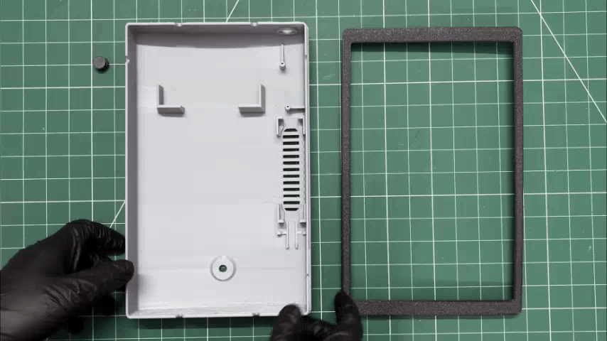
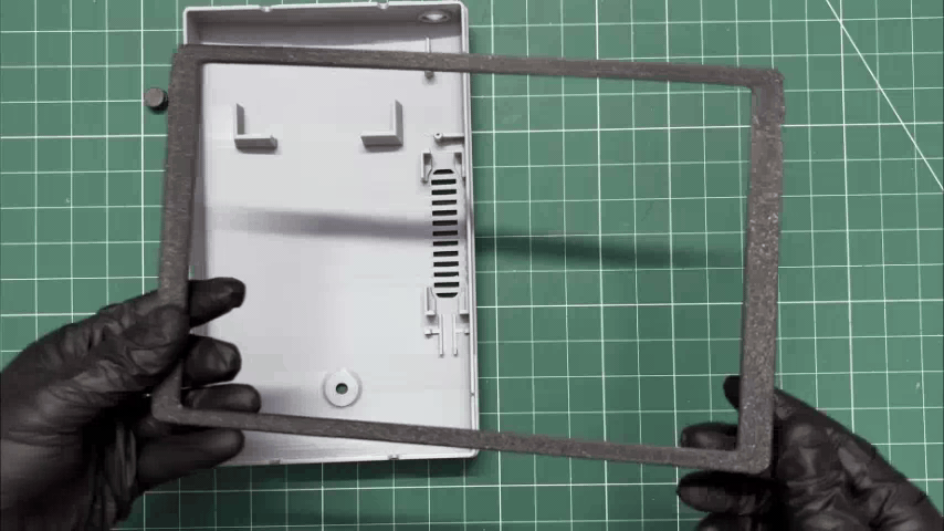
After finishing the model, we exported three parts: the back part, the frame, and the button actuator.
The frame part and button actuator were both printed in Black Hype PLA with a 0.2 mm layer height and 25% infill. The enclosure was printed in Grey Hype PLA with similar settings.
DISPLAY & CM5 ASSEMBLY
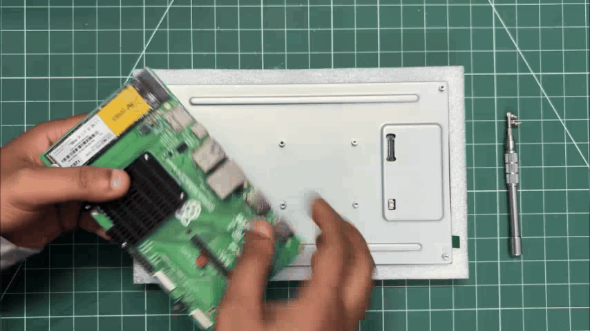
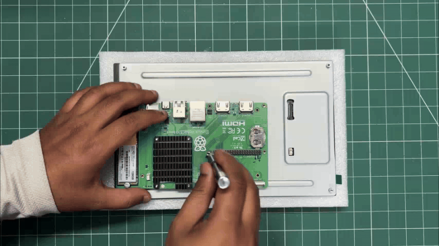
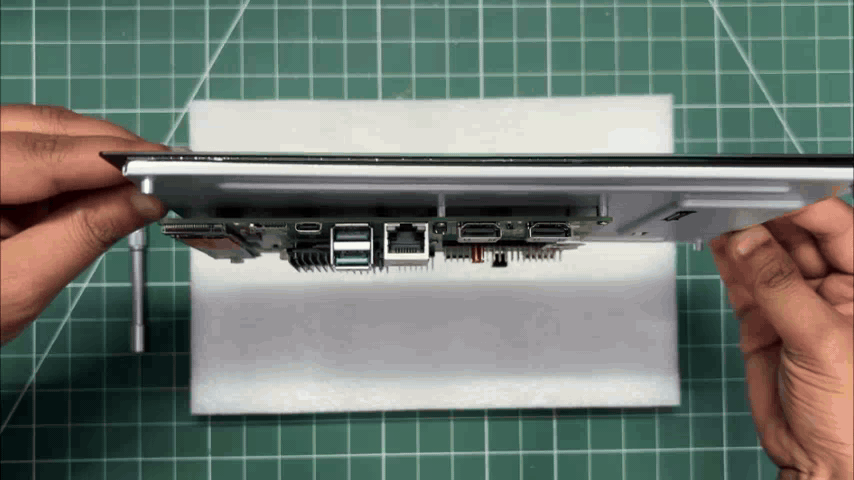
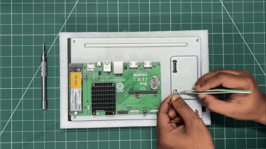
- We begin the display and CM5 assembly process by positioning the expansion board over the back of the display.
- We align the mounting holes of the display with the Raspberry Pi board and then use the provided four M2.5 bolts to secure both of them together.
- Next, we connect the power wire harness. One side is connected to the JST connector on the display, while the other end goes to the Raspberry Pi's GPIO header. We connected 5V to 5V and GND to GND. Basically, the display will be powered directly from the GPIO header of the Raspberry Pi.
CONFIG FILE EDIT
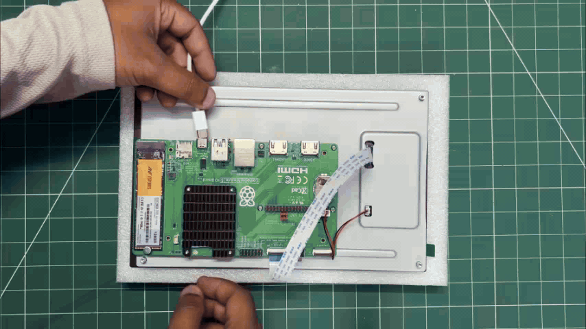
We plugged in the power and were hoping this would be a plug-and-play job, but things are never that simple, and the display didn't work straight away.
We needed to connect an external monitor to our CM5, open a terminal, and then edit the config.txt file.
We added the following line at the bottom of the file.
On the wiki page for this display, to Waveshare's credit, they did include a custom pre-flashed Raspberry Pi OS Trixie image. If we use that image and flash our Raspberry Pi with it, the display boots up without requiring any manual edits to the configuration files.
CM5 & MAX98357A ASSEMBLY
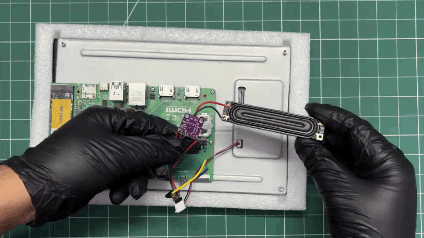
Now comes the assembly process for the MAX98357A I2S amplifier and Raspberry Pi CM5.
- We start by connecting the 5V and GND pins of the CM5 to the VCC and GND pins of the MAX98357A.
- Next, we connect the BCLK pin of the MAX98357A to GPIO18 on the CM5 GPIO header, followed by connecting LRC to GPIO19 and DIN to GPIO21.
- Finally, we connect the speaker's positive and negative terminals to the Speaker positive and speaker negative outputs on the MAX98357A amplifier, completing the audio connection between the CM5 and the speaker.
FRAME & CM5-DISPLAY ASSEMBLY
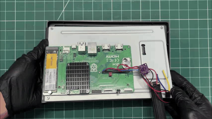
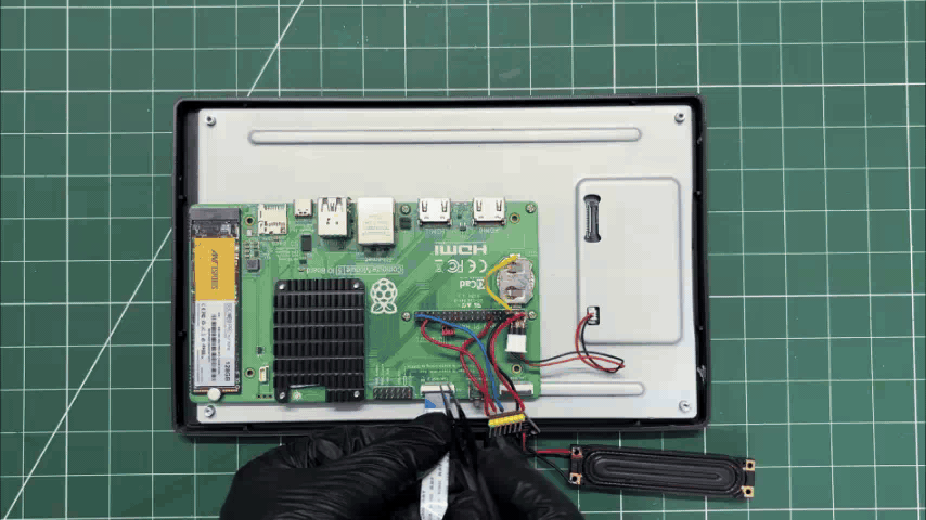
- The display is now placed into the frame, making sure it sits properly in position.
- We then reconnect the CM5's DSI connector to the display's DSI connector for video and touch communication.
- Finally, we connect the display's power input to the 5V and GND pins on the CM5, providing the required power to the screen.
POWER SOURCE & ENCLOSURE ASSEMBLY
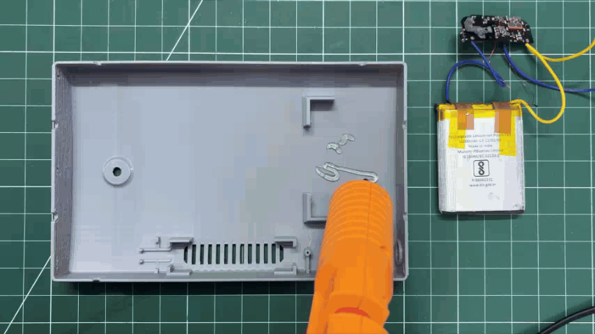
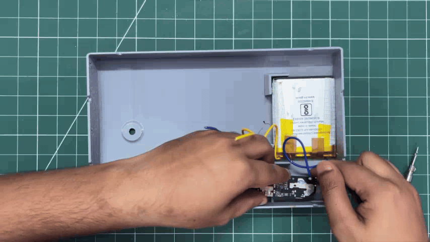
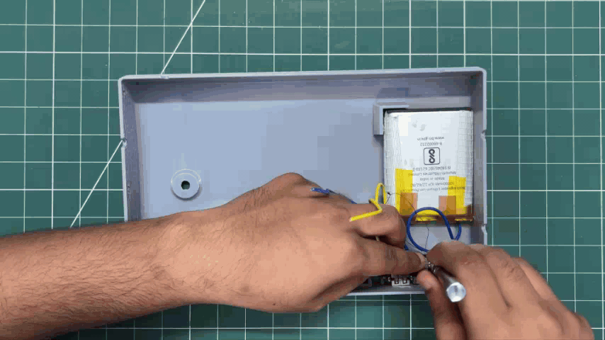
- Inside the enclosure, we apply a small amount of hot glue and place the lithium-polymer battery in position. The hot glue helps keep the battery securely in place and prevents it from shifting inside the enclosure.
- Next, the power bank circuit is positioned over the two mounting screw bosses and secured using M2 screws, keeping the board firmly mounted inside the enclosure.
FINAL ASSEMBLY
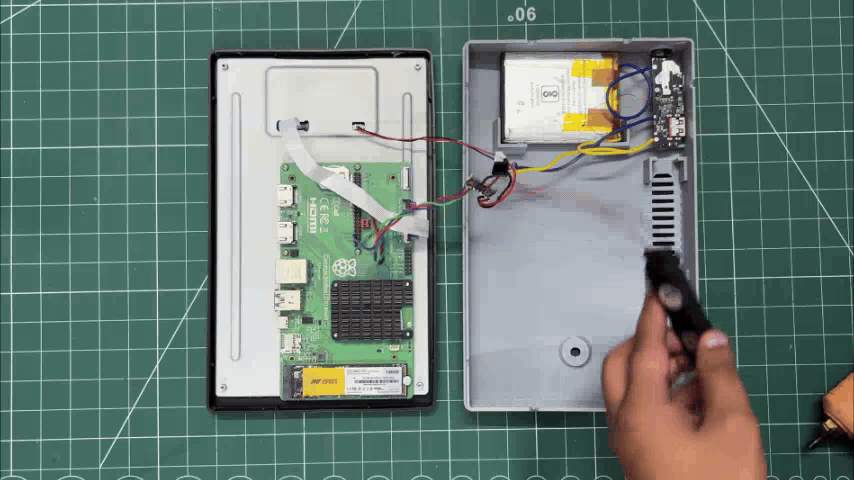
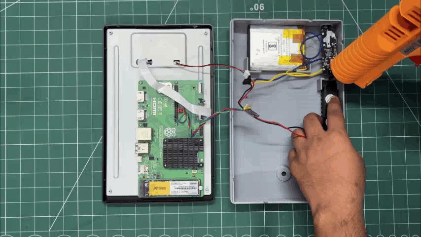
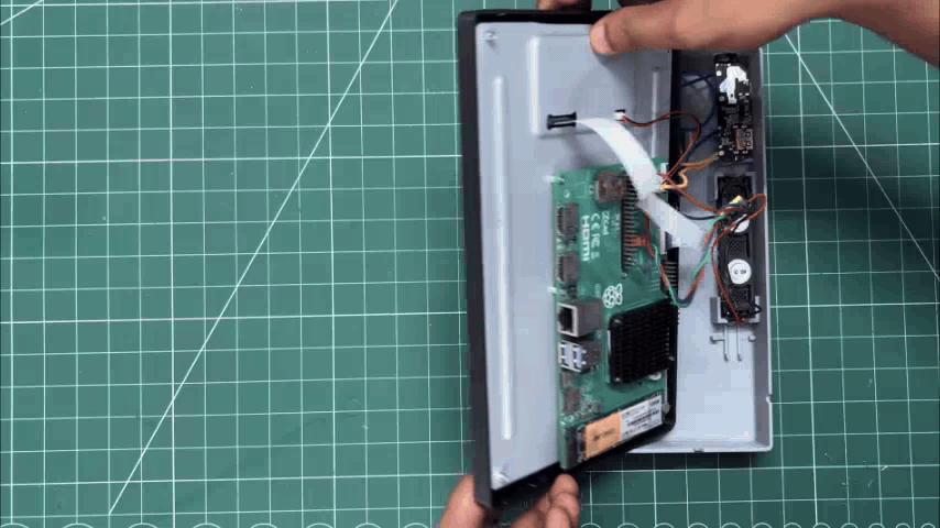
- We position the speaker inside the enclosure and apply a small amount of hot glue to securely hold it in place.
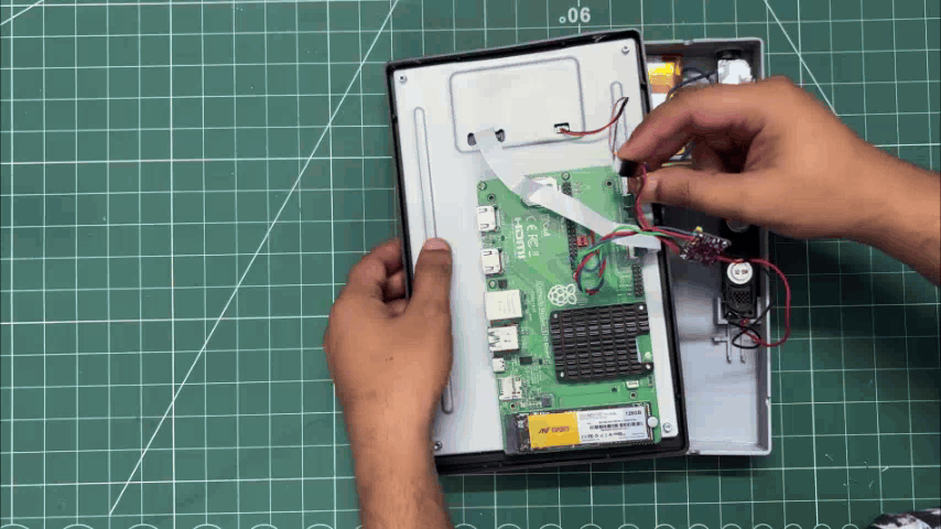
- Next, the frame and enclosure are aligned and fitted together, joining the two main sections of the body.
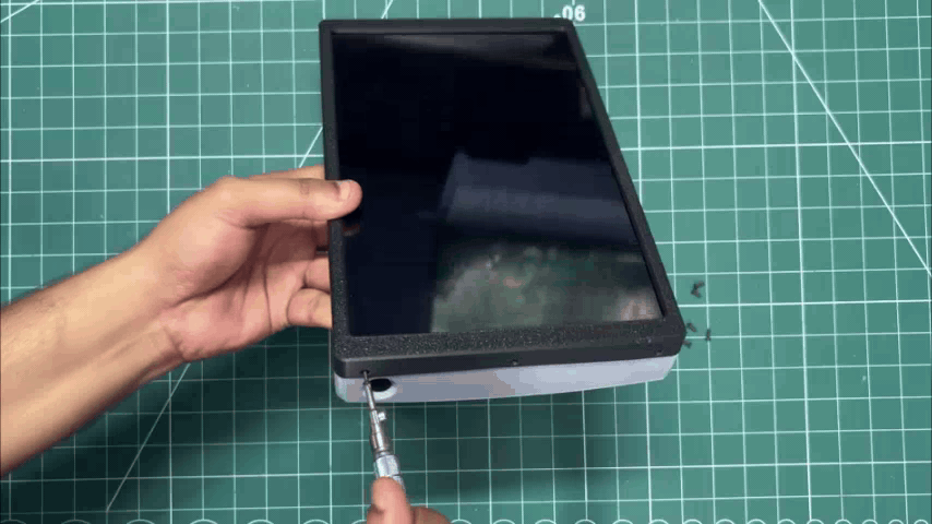
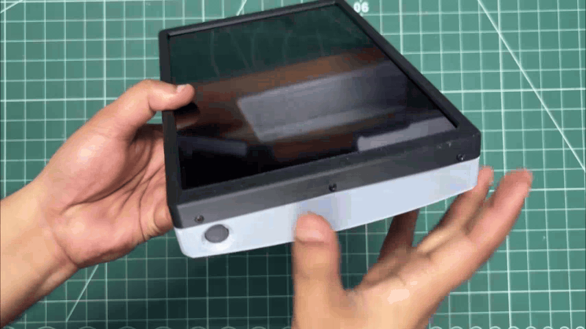
- Finally, we use six M2 screws, installed from both the top and bottom sides, to firmly secure the frame and enclosure together, permanently joining the two parts.
- With that, the assembly of iBrick is complete.
RESULT

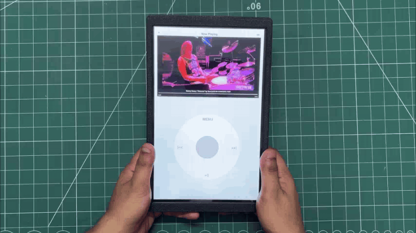
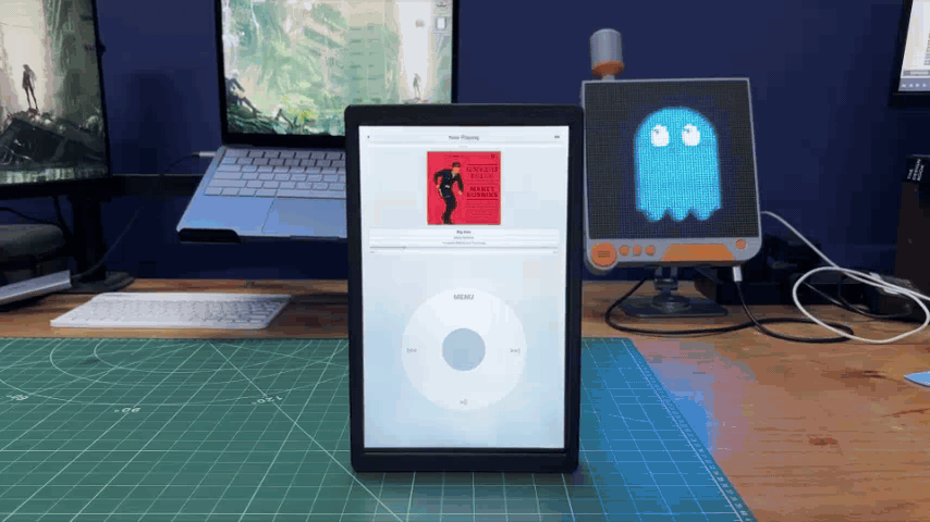
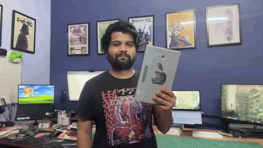
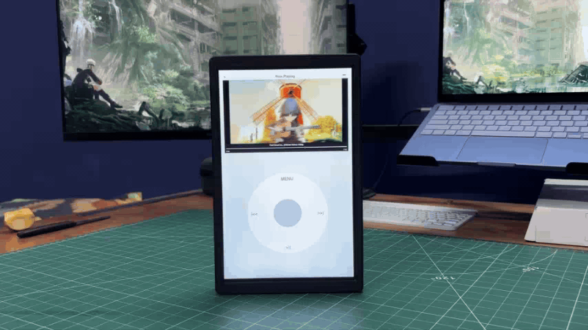
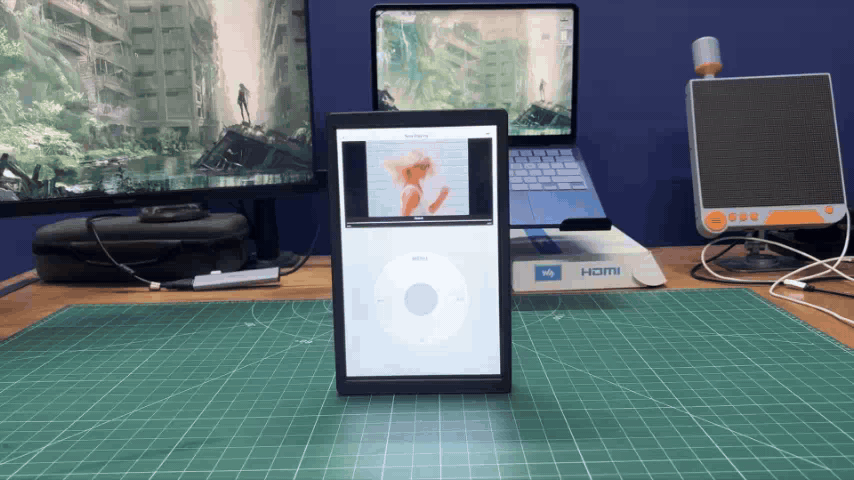
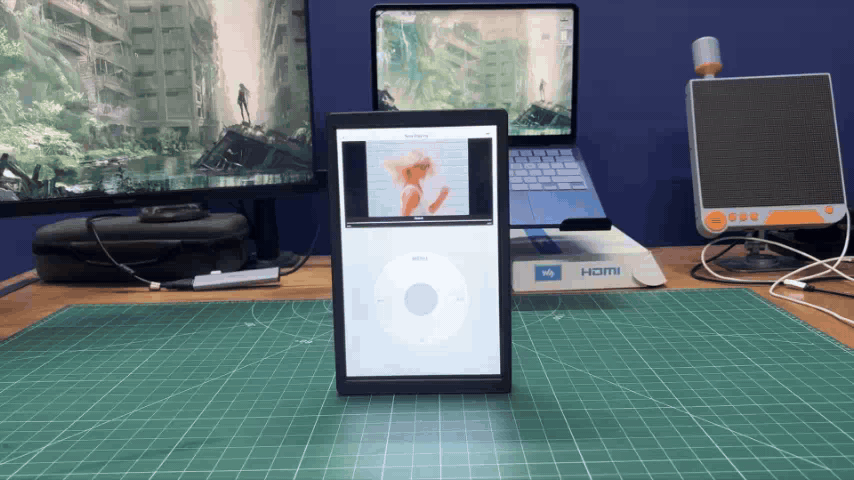
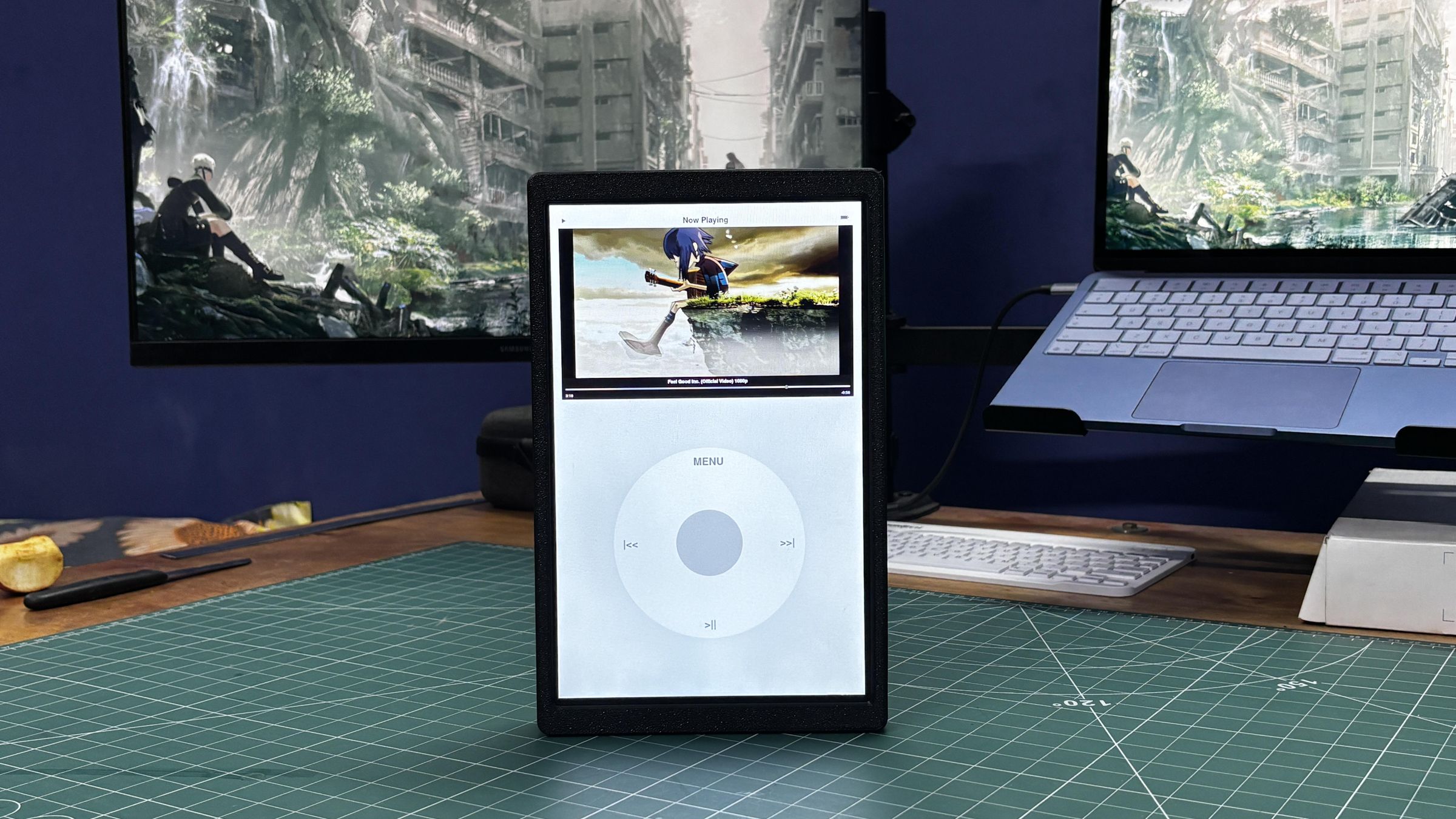
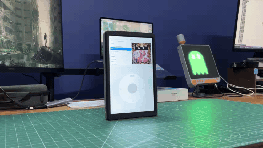
And here's the final result: iBrick, a giant iPod Nano-inspired music player with a custom software interface designed to closely recreate the look and feel of the original iPod.
Underneath the interface, it's essentially a Raspberry Pi-powered tablet running my custom iPod software. It can play locally stored music and video files, with a built-in video player and internal speakers for audio playback.
The onboard battery also makes it completely portable, providing around 4–5 hours of backup runtime on a single charge.
This project is essentially a modified version of my Absolute Linux Tablet. I reused the same core hardware and electronics, but replaced the original enclosure with a completely new design and developed new software to transform it into an iPod-inspired media player.
The result is definitely thicker than an actual iPod Nano, more like a brick, hence the name iBrick.
But that's also what makes it fun: it's a ridiculously oversized, fully functional recreation of a classic iPod Nano, built with modern hardware and a lot of nostalgia.
CONCLUSION
iBrick was a relatively straightforward build, mainly because I was able to repurpose the hardware from my previous Absolute Linux Tablet project instead of designing and assembling an entirely new system from scratch. The Raspberry Pi CM5, display, power system, and most of the electronics were already working, so the main challenge was designing a new enclosure and developing the software to recreate the iPod experience.
There are still a few things I would like to improve in a future version. The built-in speaker could definitely be replaced with a larger and better-quality speaker for a more satisfying audio experience. I would also like to use a slimmer battery to make the enclosure less bulky and improve the overall proportions.
And, of course, if I build another version, I might as well go even bigger. At the moment, iBrick uses a 10-inch display, so calling it a "giant" iPod is slightly debatable. A significantly larger version would make the whole concept even more ridiculous, and that's exactly what makes it fun.
Overall, iBrick started as a simple hardware reuse project and turned into a fun way to recreate a piece of tech I always wanted, while giving an old project a completely new life.
For now, this project is complete.
All the files related to this build have been attached, and the complete build instructions are included in this article. If you need any help, feel free to leave a comment.
Check out my other cyberdeck projects (I have made too many cyberdecks hehe)
https://www.instructables.com/VAULT-TEC-AIR-TERMINAL/
https://www.instructables.com/PARALLEL-PC-Wood-Edition/
https://www.instructables.com/CYBERPY-Zero-Three/
https://www.instructables.com/CyberPY-Zero-One/
https://www.instructables.com/Cyber-PY-Zero-Two/
Thanks for making it this far, and I'll be back with a new project real soon.
Peace.