IDC #1: Wireless Motion-Activated LED Display.
by burke_pete15 in Circuits > Arduino
184 Views, 0 Favorites, 0 Comments
IDC #1: Wireless Motion-Activated LED Display.


This instructable details the components and steps I took to create a motion sensor device that wirelessly transmits a signal upon detection to a wireless receiver that then responds by activating a specific LED light on the display. The goal of this project was to create a display of a daily routine and create a sensor that could wireless transmit when triggered. That would then turn on an LED light on a checklist of the daily routine. The goal of this device was to create a visual and physical display that could be used to help remind people of the task of daily maintenance. This can be difficult for Neurodivergent, and ADHD individuals who often struggle to remember these things and struggle with routine apps due to the lack of object permanence.
This project was developed with the help of the BTU Lab in the ATLAS Institute at The University of Colorado, Boulder.
Supplies
All components are listed below (with w/purchase links attached). For the NRF23L01 you only need two components to complete this project. For the HC-SR501 you will only need one. As well only two capacitors are needed and an additional seven Male to male-to-female jumper Cables with what comes with the ELEGOO Starter Kit. For an exact list of all items used please refer to the pdf.
- ELEGOO UNO Project Super Starter Kit with Tutorial for Arduino
- Arduino Uno REV3 [A000066]
- HiLetgo 4pcs NRF23L01 + Wireless Transceiver Module2.4G Wireless transceiver Module
- HiLetgo 3pcs HC-SR501 PIR infrared Sensor Human Body Infrared Motion Module for Arduino Raspberry Pi
- ELEGOO 120pcs Multicolored Dupont Wire 40pin Male to Female, Breadboard Jumper Ribbon Cables
- 100uf 50V 100MFD 50Voltage +/-20% Aluminum Electrolytic Capacitors
Downloads
LED Lights


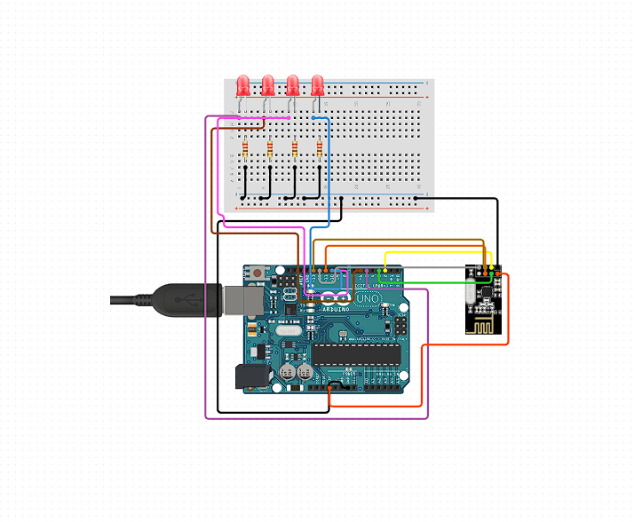
Place each LED on the 830 Breadboard with a Capacitor between the LED and GND. Using Jumper Wires connect the positive terminals of the LED lights to the microcontroller placing the Jumper Wires in the proper pins. Attached below is the code to test out the LED Display.
- LED 1 - Pin 5
- LED 2 - Pin 9
- LED 3 - Pin 6
- LED 4 - Pin 10
Motion Sensor


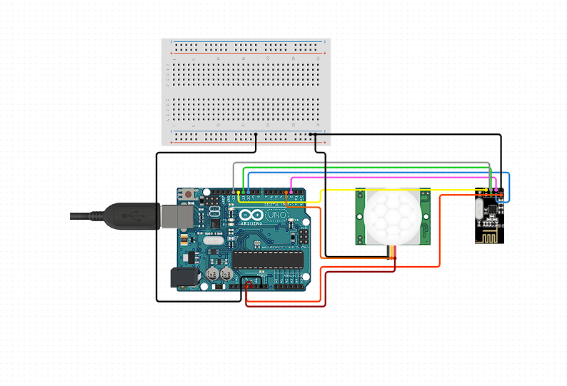
For the PIR Sensor, you will need to use male-to-female wires to connect it to the minicontroller. Looking at the PIR Sensor with the Pinout facing you the pins are as follows and connect to the following pins.
- Left: GND - GND
- Middle: OUT - Pin 2
- Right: VCC - 5V
Attached below is the code to test out the PIR Sensor.
Note: The final version of this project will use a Mini Breadboard to ground the PIR Sensor.
Troubleshooting: Turning the PIR Sensor upside down we can see there are two potentiometers. The left one adjusts the sensitivity of the sensor (i.e. the range), and the right one is the Time-Delay Adjustment which determines how long the sensor outputs detection after it is activated. If the sensor is always triggering try decreasing the Sensitivity and Time-Delay.
- Turn CW to increase, and CCW to decrease
Wireless Transmitter/Receiver
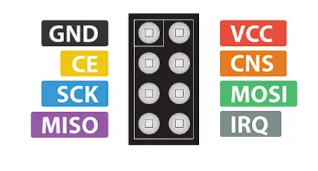


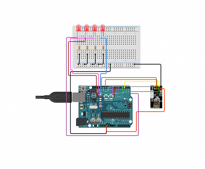
To connect the receiver and transmitter to their respective mini controllers will require seven male-to-female wires connected identically on both. Following the display of the Pinoout below the wires are connected to the following pins on the microcontroller.
- GND - GND
- VCC - 3.3V
- CE - Pin 7
- CNS - Pin 8
- SCK - Pin 13
- MOSI - Pin 11
- MISO - Pin 12
Once the NRF23L01 modules are connected we need to download and install the RF24 library This will make programming easier, we can install this library directly from the Arduino IDE Library Manager. Search for "rf23" and find and install the one by "TMRh20, Avamander".
Attached below is the code for the NRF23L01 Wireless Transceiver Module 2.4G. Created by Dejan Nedelkovski
Troubleshooting: If you are having trouble with sending and receiving a signal it could be due to power supply noise. A simple way to fix this is to connect a decoupling capacitor across the power supply. The capacitor can be anywhere from 10uF to 100uF.
Note: This was a necessary step for my project and was implemented.
Display/Enclosure


The display was created using SketchUp and laser-cutting while the enclosures were created using SketchUp and 3D printing.
- The display is made of 3/4 thick plywood (which was thicker than needed!!!)
- The display enclosure is made to hold the LED Lights, microcontroller, NRF23L01 module (receiver), and 9V battery.
- The enclosure for the PIR Sensor and NRF23L01 module (transmitter) is made to be open to allow access to the USB port. The support structure holds the sensor keeping it steady and facing a constant direction.
Files for 3D Printing and laser cutting display and enclosures.
Note: Make sure to measure the distances of the holes for the LED displays, making sure the Breadboard holds the LED in the correct position.
Downloads
Code
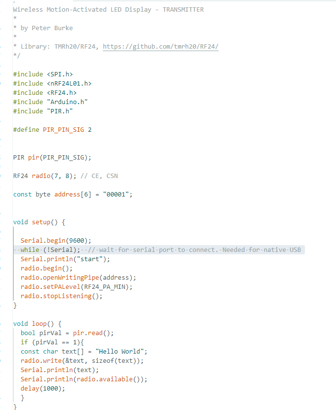
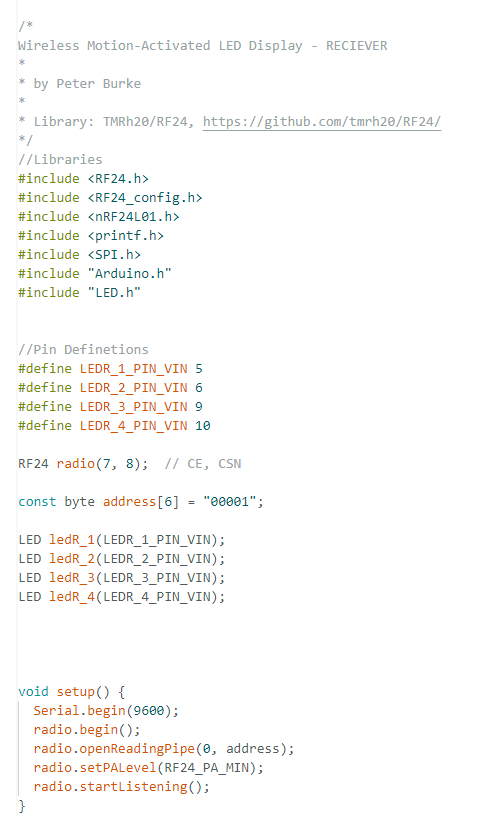
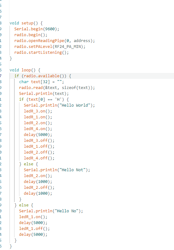
At this point, your circuits should look like the ones pictured above. (The decoupling capacitors are only needed if the signal is not being received). Now that the circuits are set up it's time to code the microcontrollers.
Transmitter: Will check the input of the PIR sensor and if it detects motion will then send a signal through the NRF23L01 module to be received by the receiver.
Receiver: The NRF23L01 module receiver will receive a message signifying motion has been detected by the transmitter circuit. It will then turn on the 4 LED lights signifying the Daily Routine has been completed.
The code for the transmitter and receiver is attached below.
CONGRATULATIONS! You have created a wireless motion-activated LED display.
Sources/Credits
All files and versions are in the Project Library.
I could not have done this project without help from so many amazing resources. They are included below.
- NRF23I01 Tutorial by Dejan Nedelkovski
- HC-SR501 PIR Sensor Tutorial by Last Minute Engineers
- Display Circuit on Circuito.io
- Transmitter/Sensor Circuit on Circuito.io
- nRF24 Github Repo by TMRh20, Avamander"
Additional Pictures




Additional photos and video of the finished project are included.