Industrial GPIO Expander – MCP23017
by DIY GUY Chris in Circuits > Electronics
63 Views, 0 Favorites, 0 Comments
Industrial GPIO Expander – MCP23017
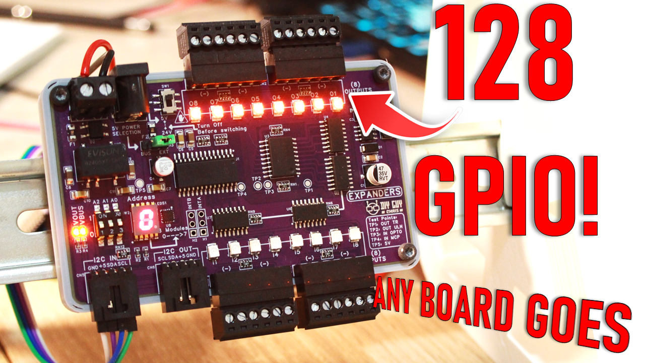
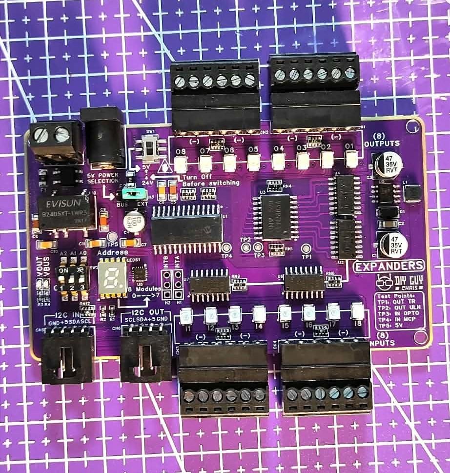
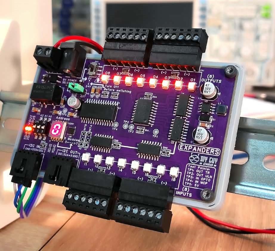
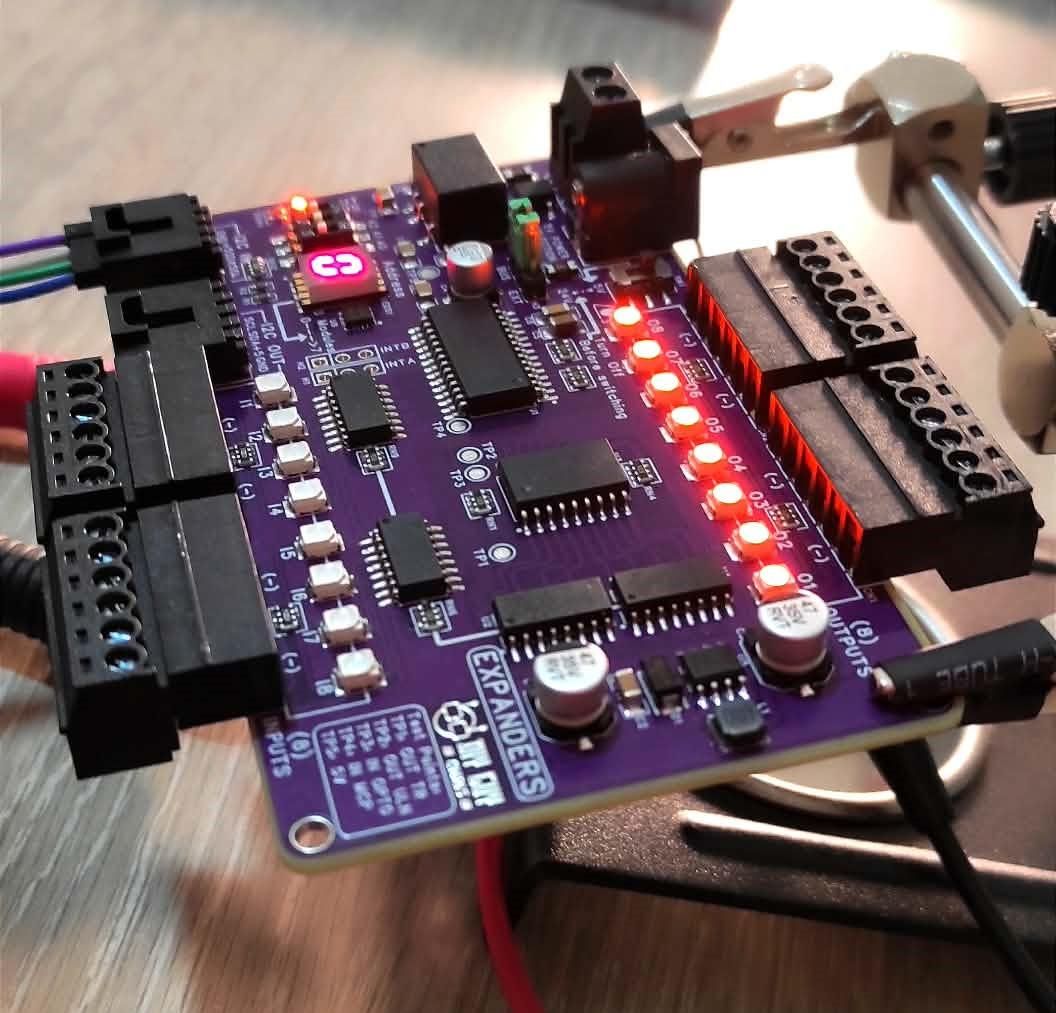
This project provides a simple way to add 16 extra I/O pins to your microcontroller using the MCP23017 chip . It's designed for easy installation in electrical cabinets with a DIN-rail mount , making it practical for real-world automation projects. The board comes with built-in protection, flexible power options (5V or 24V), and visual indicators for every input and output.
Supplies
Main ICs:
- MCP23017 (I²C I/O Expander)
- ULN2803A (High-current driver)
- TLP291-4 (Optocouplers)
Power:
- MB2S (Bridge rectifier)
- XL1509-5.0E1 (DC-DC converter)
- AMS1117-3.3 (Voltage regulator)
PCB & Assembly:
- 2-layer PCB (103×60mm)
- SMD components (resistors, capacitors, LEDs)
- Terminal blocks (screw connectors)
- 3D-printed DIN-rail enclosure (STL files included)
Optional:
- Arduino UNO (for testing)
- I²C cables
- Soldering tools (hot plate, iron, tweezers)
Schematic Design
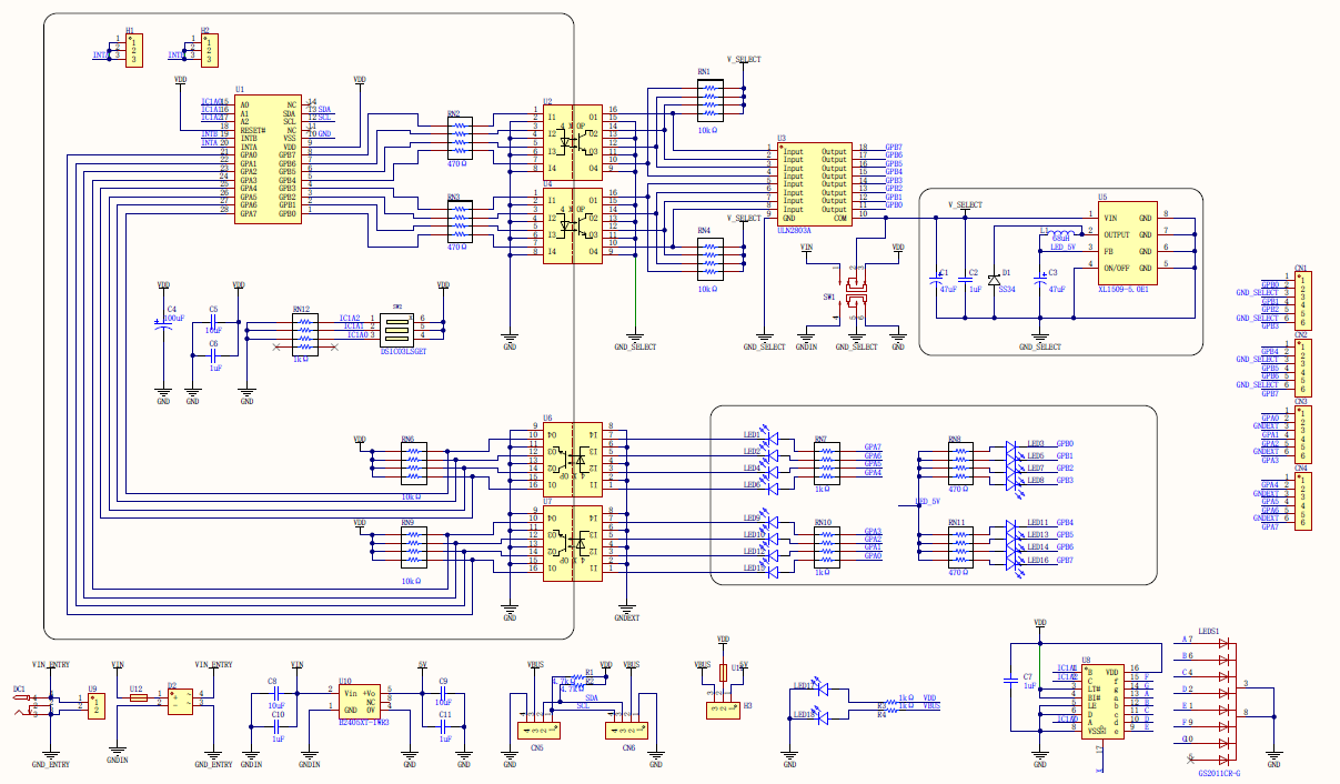
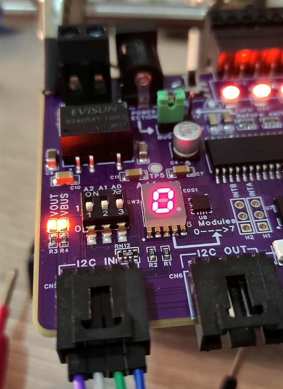
Design the circuit in Altium starting with the power entry: a bridge rectifier for reverse polarity protection, followed by a DC-DC converter to step down voltage to 5V. The MCP23017 connects to the I²C bus and drives 8 outputs through the ULN2803A. For inputs, use TLP291-4 optocouplers to isolate the 8 input channels from external peripherals . Add a 3-position slide switch for hardware address selection (0-7) and a 7-segment display to show the address.
Downloads
PCB Layout
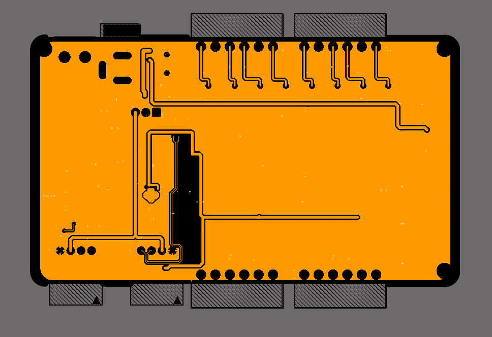
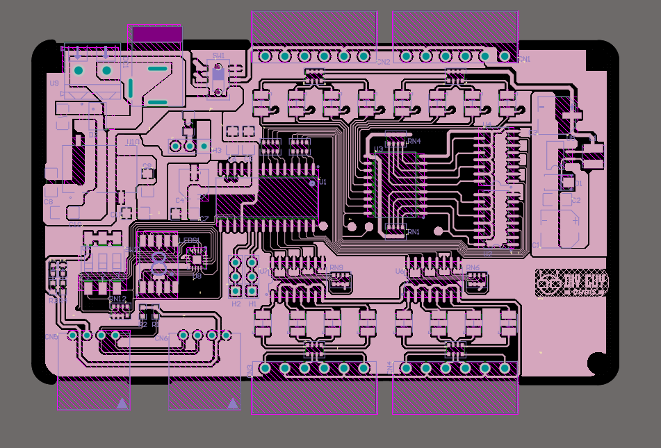
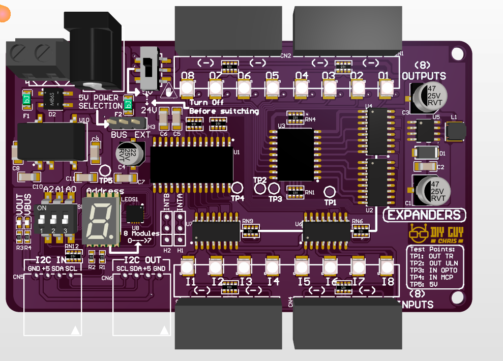
Route a 2-layer PCB following industrial PLC standards: power entry at the top left, outputs along the top edge, inputs along the bottom edge, and I²C connectors at the bottom right . The board measures 103×60mm and includes status LEDs for all 16 I/O channels, you can access the full project design files through my Altium Online Repository. For manufacturing, export Gerber files and upload them to JLCPCB.
Assembly
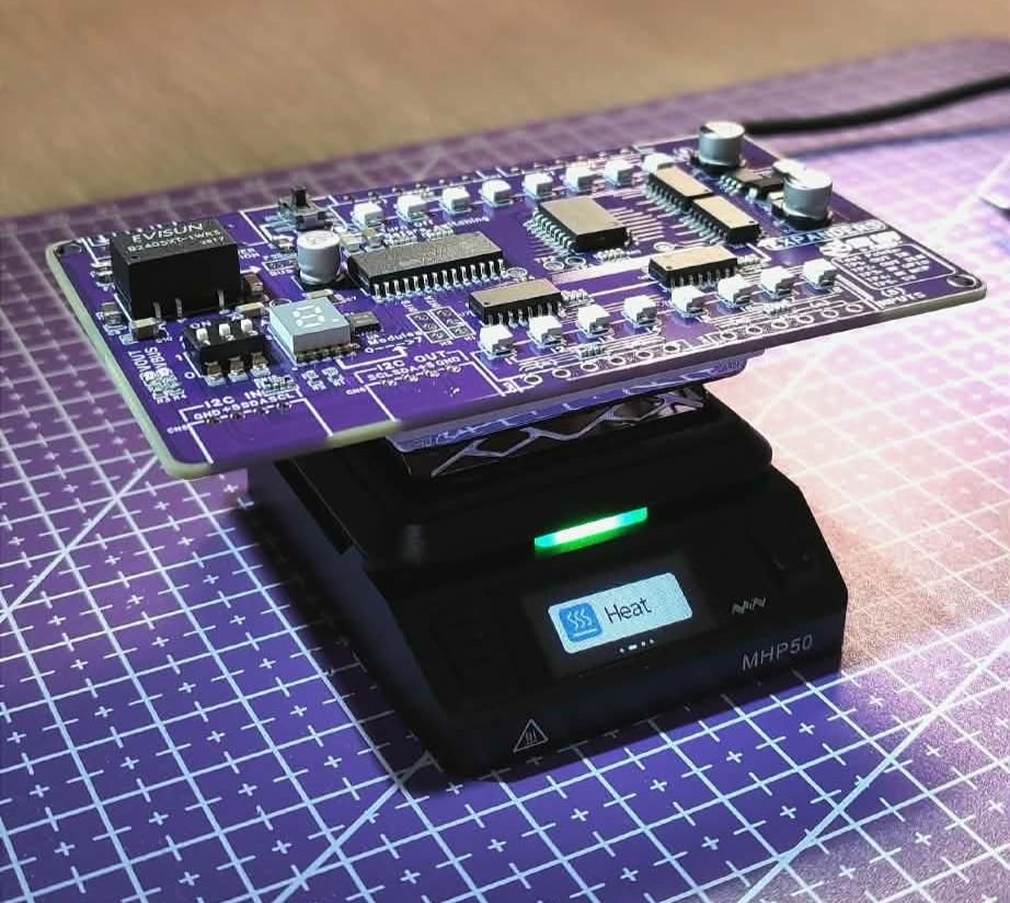
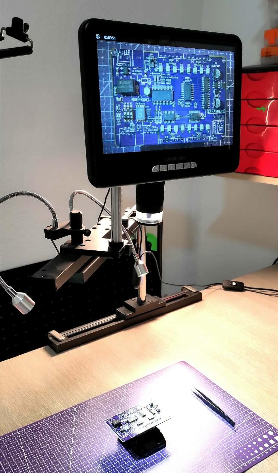

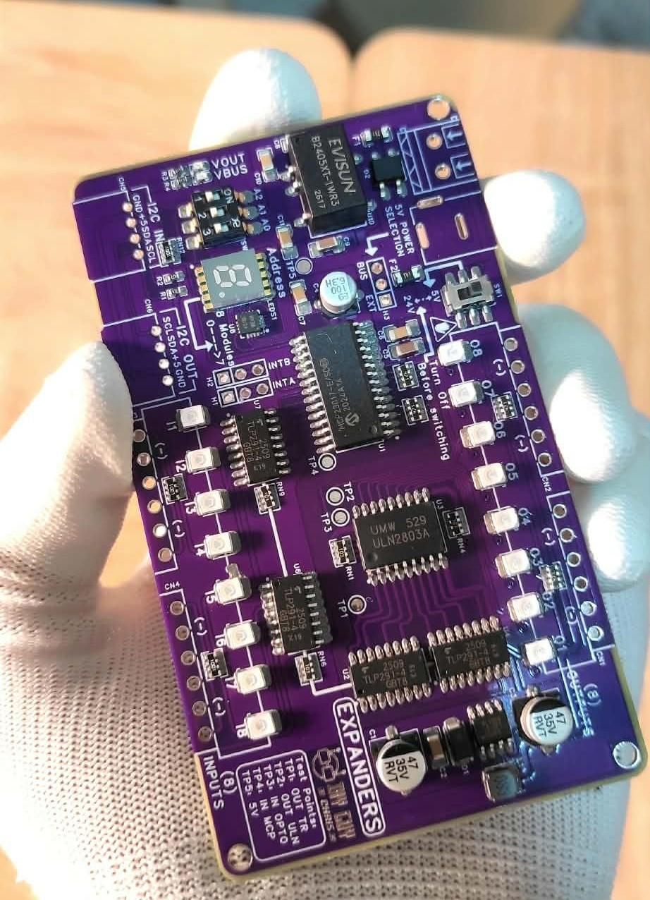
Apply solder paste through a stencil, then place SMD components (resistors, capacitors, ICs) using tweezers. Reflow the board on a hot plate at 245°C peak temperature, then solder through-hole components (terminal blocks, connectors) with a soldering iron . Clean the board with isopropyl alcohol and inspect for bridges under a microscope.
Testing & Enclosure