Interacting With an OLED and an Accelerometer
by JayconSystems in Circuits > Sensors
4757 Views, 28 Favorites, 0 Comments
Interacting With an OLED and an Accelerometer

In the previous tutorial, we learned how to use an OLED to display different shapes. We started by drawing a pixel, and from there we were able to draw lines, rectangles, squares, and circles. However, each display took us a considerable amount of time and effort. Fortunately the JUGL library can be used to do the same, and more, in less time and in a much easier way. The library supports the following features:
- Pixels
- Lines
- Rectangles
- Squares
- Polygons
- Circles
- Triangles
- Text
Introducing the Accelerometer ADXL335

In this tutorial we are going to show how to use the library to display a ball and make it move around the screen using an accelerometer. The accelerometer that we will be using is the ADXL335.
This sensor measures acceleration, like the one due to gravity, on the x, y and z axes. Thus, if the sensor is at rest parallel to ground, only one of the axes will feel the acceleration of gravity. As you tilt the device, other axes will start feeling the acceleration of gravity too. This way, it is possible to analyze the way the device is moving.
Adding the Accelerometer to the OLED Set-up

So now that we know how the OLED and accelerometer work, it is now time to create our setup.
First we need to add the sensor to our OLED setup in the following way as shown in the image above.
The sensor’s pins are connected to the Arduino as shown below:
- VCC – 5V
- GND – GND
- X – A3
- Y – A2
- Z and ST are left unwired
The Code
Once we have the wiring set up, we can use the following code to create our game:
<br><p>#include <JUGL.h><br>#include <SPI.h>
#include <Wire.h>
#include <JUGL_SSD1306_128x64.h>
using namespace JUGL;
SSD1306_128x64 driver;

const int xpin = A3; //Assign pin A3 to x
const int ypin = A2; //Assign pin A2 to y
int x, y, x1, y1, r, varx, vary, width, height; //Define variables
int xy [2]; //Array to hold (x,y) coordinate

//Declaration of functions
void Circle(IScreen& scr);
void move_right(IScreen& scr);
void stop_right(IScreen& scr);
void move_left(IScreen& scr);
void stop_left(IScreen& scr);
void move_up(IScreen& scr);
void stop_up(IScreen& scr);
void move_down(IScreen& scr);
void stop_down(IScreen& scr);

void setup(){
  IScreen& screen = driver;  //Make reference to driver
  screen.Begin(); //Initialize screen
  width = screen.GetWidth(); //Get width of screen (128)
  height = screen.GetHeight(); //Get height of screen (64)
  Circle(screen); //Draw circle
}

void loop(){
  x1 = analogRead(xpin); //Read x analog data
  y1 = analogRead(ypin); //Read y analog data

  IScreen& screen = driver; //Make reference to driver

  if(x1<500){ //Check if sensor is tilted to the right
  move_right(screen); //Move ball right
  if(varx>=width-1-r ){ //Check if ball reached end of screen
    stop_right(screen); //Stop moving
  }
  }

 if(x1>520){ //Check if sensor is tilted to the left
 move_left(screen); //Move ball left
 if(varx=height-1-r){ //Check if ball reached end of screen
 stop_up(screen); //Stop moving
 }
 }

 if(y1>510){ //Check if sensor is tilted down
 move_down(screen); //Move ball down
 if(varyr){ //Check if ball is within boundaries
  scr.Flush(); //Display on screen
  }
}

void stop_left(IScreen& scr){
  scr.Clear(); //Clear screen
  varx = r; //Update varx
  xy[0] = varx; //Store new varx value
  scr.FillCircle(Point(5,xy[1]),r); //Draw circle
  scr.Flush(); //Display on screen
}

void move_up(IScreen& scr){
  scr.Clear(); //Clear screen
  vary += 10; //Move ball 10 pixels up, assign value to vary
  xy[1] = vary; //Store new vary value
  scr.FillCircle(Point(xy[0],vary),r); //Draw circle
  if(varyr){ //Check if ball is within boundaries
    scr.Flush(); //Display on screen
  }
}

void stop_down(IScreen& scr){
  scr.Clear(); //Clear screen
  vary = r; //Update vary
  xy[1] = vary; //Store new vary value
  scr.FillCircle(Point(xy[0],5),r); //Draw circle
  scr.Flush(); //Display on screen
}</p>
Code Explanation
So here is what’s going on in the code. First we include all the libraries that we need to run this program. The JUGL library contains the function required to draw the circle, while the JUGL_SSD1306_128x64 library is used to initialize the screen. This last library also contains the “DrawPoint” and “Flush” functions to draw each of the circle’s pixels and display them on the screen. The SPI and Wire libraries are used to communicate with devices via SPI or I2C. In this case, we are using I2C communication. Since the library supports many drivers, it is required to specify which one we are using. Line 6 takes care of this by specifying that we will be using driver SSD1306 on a 128x64 screen. Below are the other drivers that this library supports:
- EPD 2.0
- EPD 1.44
- EPD 2.7
- PCF8833
- KS0107
In the next part of the code, we assign the Arduino’s analog inputs A3 and A2 to the x and y pins of the sensor, respectively. We also define the variables that we are going to use and create an array to hold the x and y coordinate (origin of the ball). Then we make a forward declaration of the functions that we will be using in this program.
Next, we move to the setup part of the code. In here, we make a reference to the driver that we are using. Based on the reference, we initialize the screen, and get its width and height. Finally, we call the function, “Circle.” This function clears the screen and sets the radius and origin of our ball. We use the “FillCircle” and “Flush” functions from our library to draw the ball and display it. This generates a ball at the bottom left corner of our screen with a radius of 5 pixels and an origin at (5,5).
Sensor in Action
Now that we have our ball, we can use the sensor to make it move.
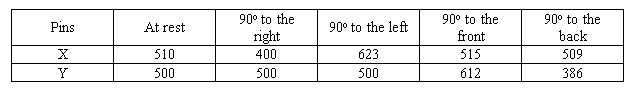
In the loop section of the program, we make a reference to the driver that we are using again. Then we read the data from pins x and y, and assign the values to variables x1 and y1 respectively. The table above shows the value of each pin depending on the inclination of the device.
By comparing the values with the values “at rest” we can determine if the device is being tilted to the right, left, etc. Let’s take the first case in our program as an example.
We know that if the device is being tilted to the right, the value “at rest” will decrease. When this happens, the program calls the function “move_right.” This function clears the screen and then adds the value 10 to variable “varx” (which in this case is zero). This represents the number of pixels that we want to move the ball’s origin in the x axis. Then we store the new value of “varx” in the first location of the array. Finally, we call the “FillCircle” and “Flush” functions to display a new circle on our screen 10 pixels away from the previous circle in the x axis. The process keeps repeating as long as the value of pin X is less than 510, thus erasing the previous circle and drawing a new one 10 pixels away from each iteration. This gives the illusion that the ball is moving to the right.
However, if the ball reaches the end of the screen, the function “stop_right” is called. This function clears the screen, sets varx equal to the 126 and stores this value in the first location of the array. Then the functions “FillCircle” and “Flush” are called to draw and display a ball with its origin at (126,xy[1]). In other words, the program will stop moving the ball 10 pixels to right, and instead it will keep drawing the same circle at the edge of the right side of the screen in whatever y location it resides.
The same idea is used when the device is tilted left, up, or down.
Sensor in Action - Continued
Every time we move the ball on the screen we need to keep track of the changes in the x and y axis. As it was stated before, this is done by storing the new values of x and y in the array every time there is a change in the ball’s origin. For example, if we move the ball to the right and stop such that the last ball drawn has an origin at (30,5), if we want to move the ball up from there, we have to take into account the change in the x axis so that when the new ball is drawn, its origin resides at (30,15). In other words, the values held in the array serve as a reference location for the next ball to be drawn.
Above is a short video of this tutorial's goal in action from the Jaycon Systems collection of video tutorials.
We hope you enjoyed this Instructable and you'll tell us how your project turns out!
If you haven't already, then check out Jaycon Systems website for more cool tutorials, and our online store where you can buy the parts you need to get creating!
We also have more interesting and fun projects for you to consider on our Instructables profile as well!
If you have any questions about this tutorial, then please do not hesitate to post a comment, shoot us an email, or post it in our forum!
Thanks for reading!