Interactive Binary Learning System: 2-Bit Adder Trainer and Binary Battle Game
by karanveer sharma in Circuits > Arduino
74 Views, 1 Favorites, 0 Comments
Interactive Binary Learning System: 2-Bit Adder Trainer and Binary Battle Game
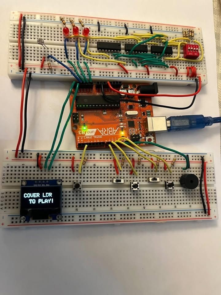
Hello! My name is Karanveer Sharma, and this project is a 2-bit binary adder built using logic gates and an Arduino, combined with an interactive game mode.
The main idea of this project is to take two binary numbers, add them using a real hardware logic circuit, and display the result on an OLED screen in both binary and decimal form. This helps make binary addition easier to understand because users can actually see how switch inputs turn into a final output through logic gates.
The project has two modes, and an LDR (light sensor) is used to switch between states. When the LDR is covered, it acts like a trigger to open the main menu, where the user can choose between Adder Mode and Game Mode. This makes the system feel more interactive and adds a simple physical way to control the project without extra buttons.
In Adder Mode, users set binary inputs using switches and press a button to see the result. The output is shown on LEDs and the OLED display in both binary and decimal form.
In Game Mode, two players compete in a binary conversion challenge. They are shown binary or decimal values and must quickly choose the correct answer using switches and buttons. The system keeps score, and a buzzer is used to give feedback and announce the winner at the end.
i combined these units to create this project:
Unit 3: Boolean Logic in Circuits (for the logic gate adder design)
Unit 4: Micro-controllers (for the Arduino code, OLED menu, and game logic)
PROJECT DEMONSTRATION VIDEO 👇👇👇👇👇👇
Downloads
Supplies
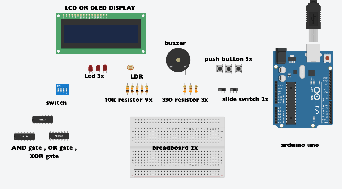
1x Standard 4 Position DIP Switch $0.98
1x Buzzer $3.3
1x LDR $1.4
1x OLED display $11
3x push buttons $0.6
2x slide switch $1.09
1x XOR Logic Gate $2.41
1x AND Logic Gate $0.95
1x OR Logic Gate $1.80
4x 10kΩ Resistors 0.40
5x 330Ω Resistors $0.50
1x Arduino UNO R3 $15.99
1x Wire Pack $14.99
2x Breadboard $4.99
total project cost : $59.40
IDEA and RESEARCH
To figure out how to combine these units, I started by researching digital logic tutorials and built a 2-bit binary adder using physical logic gates (Unit 3) to handle the actual math. It worked great, but I wanted to make it more engaging and functional, so I thought about combining it with an Arduino microcontroller (Unit 4). By coding the Arduino, I was able to add an interactive OLED screen, manage the user menu, and create a competitive game mode that tests binary skills. This allowed me to smoothly merge pure hardware logic with microcontroller programming into one fun, educational project.
The 2bit Adder
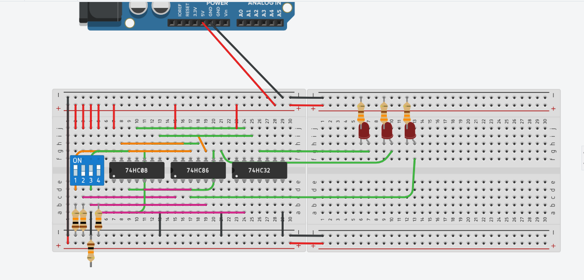
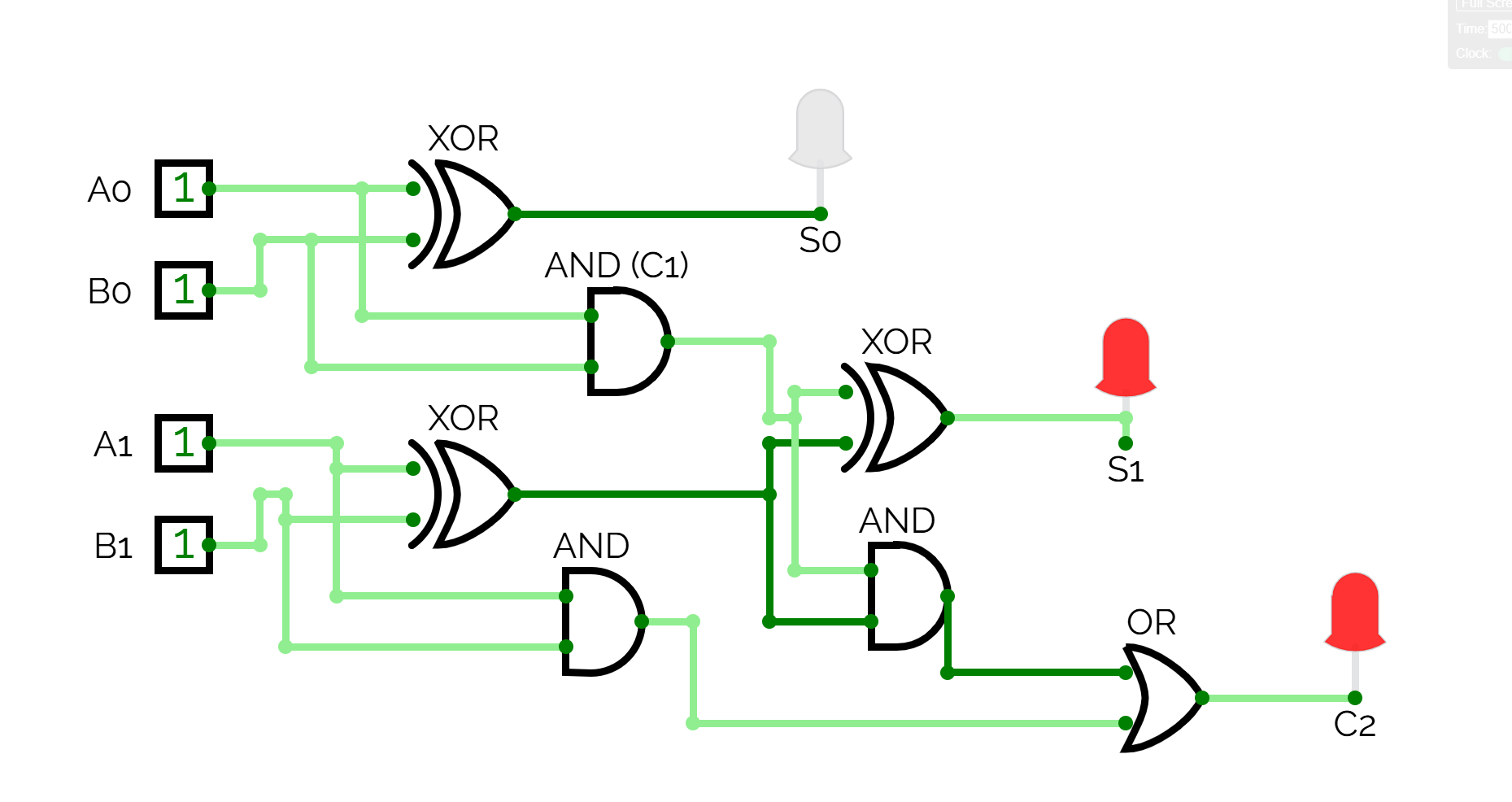
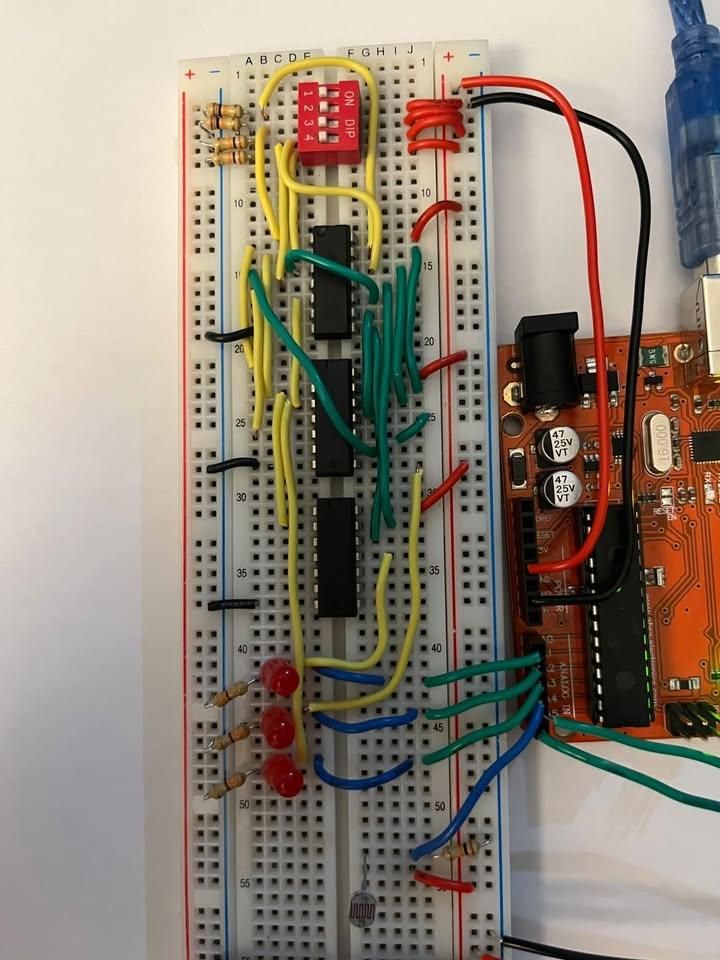
A 2-bit adder is made using two half adders:
- A 2-bit adder adds two 2-bit binary numbers (a0,a1 b0,b1) to produce a 3-bit sum (S0, S1, C2). It splits the math into two column stages:
- A 2-bit binary adder adds numbers using two parts: a half adder and a full adder. The half adder uses an XOR gate to find the first answer bit (S0) and an AND gate to create a carryover bit (C1) if both inputs are 1. The full adder then takes that carryover bit and uses two more XOR gates to find the second answer bit (S1). Finally, it uses AND and OR gates to see if a final carryover is needed, giving us the last bit (C2).
Outputs:
- S0 → 1’s place
- S1 → 2’s place
- C2 → 4’s place
Together, they form a 3-bit binary number (0–6).
- DIP switch inputs → logic gates
- Logic gate outputs → Arduino pins:
- S0 → A2
- S1 → A1
- C2 → A0
These pins allow the Arduino to read the adder result.
WIRING THE OLED DISPLAY
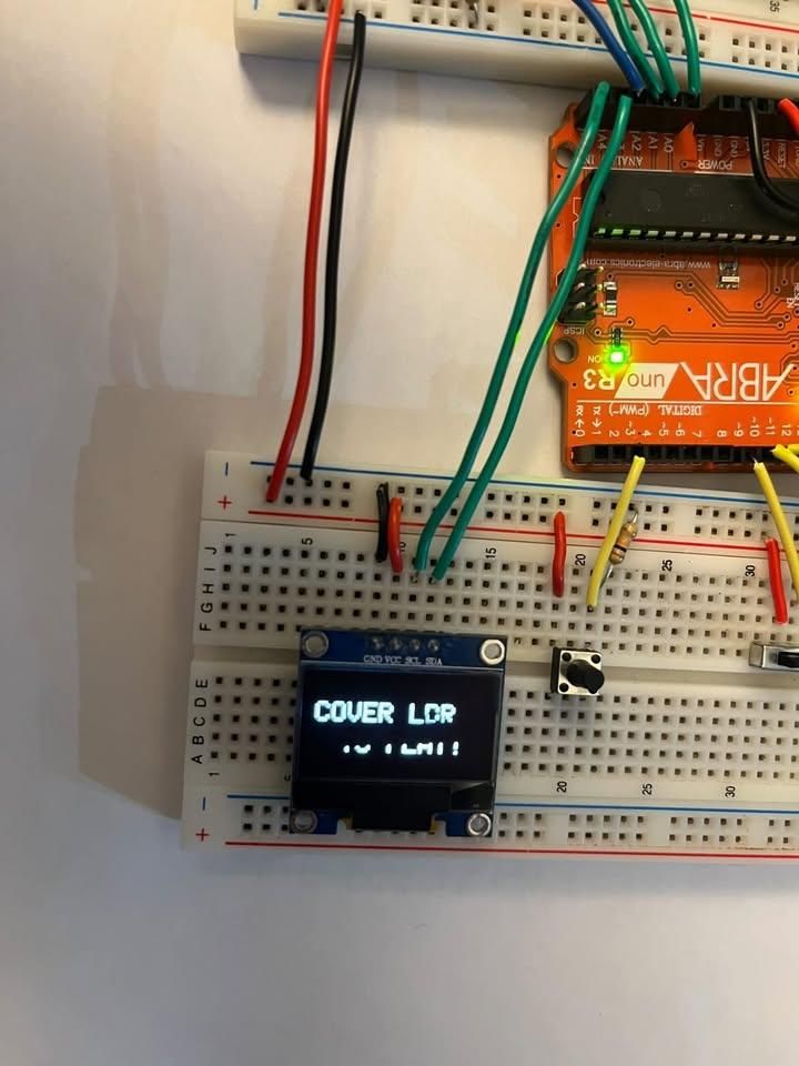
The OLED uses I²C, which only needs 4 wires:
OLED Pin Arduino Pin
VCC → 5V
GND → GND
SDA → A4
SCL → A5
The OLED displays all instructions, values, and game results.
it is very important that you connect SDA and SCL to pins A4 and A5 respectively. otherwise the OLED would not be able to communicate with the arduino.
Push Buttons and Slide Switches
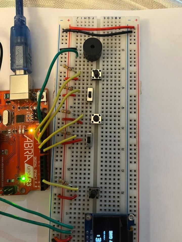
🔘 Push Buttons
- One side → GND
- Other side → Arduino pins (2, 9, 11)
- Used for:
- Adder result button (Pin 2)
- Player 1 input (Pin 9)
- Player 2 input (Pin 11)
🎚️ Slide Switches
- Middle pin → Arduino pins (8, 10)
- One side → 5V
- Used for:
- Menu selection
- Game inputs (A/B choices)
THE Buzzer
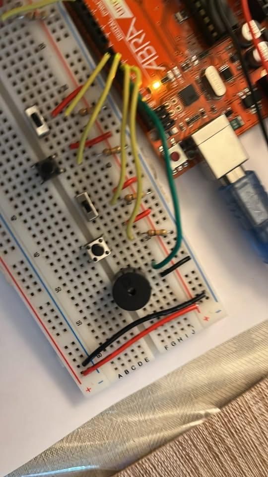
Buzzer
- Positive (+) → Pin 12
- Negative (–) → GND
How it works in the project
- Winning tune:
- Plays only when a player reaches the winning score. It runs a short melody at the end of the game to indicate the winner.
- Input feedback :
- For a correct answer, it plays a quick, high-pitched beep to let the player know they got it right.
- For an incorrect answer, it plays a lower, longer buzz to clearly signal a mistake.
GAME MODE

This mode is a two-player binary conversion game.
It is selected from the main menu using Switch 2. When started, both players’ scores are reset and a countdown begins. Each round displays either a binary number or a decimal number and two answer choices on the OLED screen.
Players respond using their assigned switches or buttons. The first player to respond locks in their answer. A correct answer gives a point, while a wrong answer gives the point to the other player.
The game continues until one player reaches 3 points. At the end, the buzzer plays a winning tune and the winner is shown on the display.
2 BIT ADDER MODE
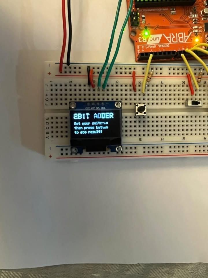
This mode is used to learn how binary addition works using real hardware.
It is selected from the main menu using Switch 1. Once entered, the user sets two binary inputs using the switches connected to the adder circuit. After setting the values, the user presses the adder button to see the result.
The OLED display shows both the binary output (C, S1, S0) and the decimal value. The LEDs also show the same binary output in real time. To exit, the LDR can be uncovered to return to the main menu.
LDR
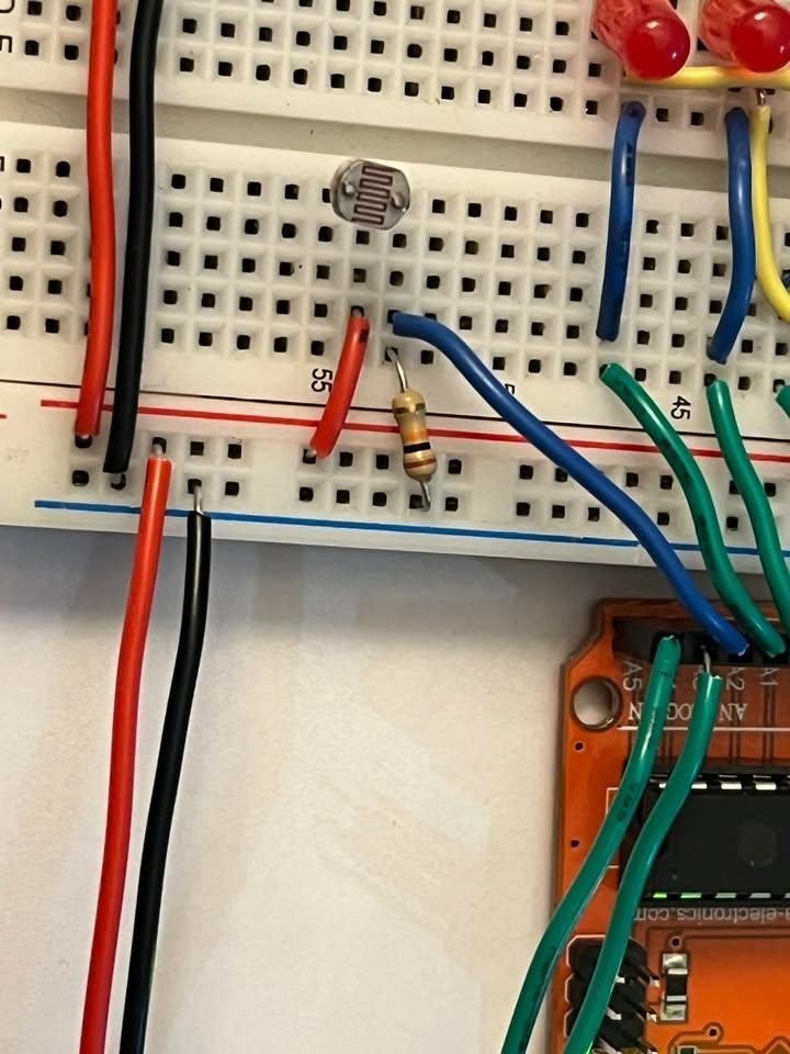
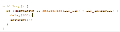
The LDR is used as a simple control sensor for the project.
It is connected to an analog pin and constantly reads light levels. When the LDR is covered (low light), it triggers the system to start and opens the main menu. When it is uncovered again (high light), it is used to return the system back to the idle screen.
analogRead(LDR_PIN) reads the light level on pin A3 — in a lit room this number is high. The moment you cover the LDR with your hand, the number drops below 80 (the threshold), and that triggers showMenu()
Common Mistakes :
OLED Display
- Swapping SDA and SCL wires
- Not connecting VCC to 3.3V — some OLED modules burn out on 5V
- Forgetting to connect GND
LDR
- Not using a resistor in the voltage divider with the LDR — without it analogRead() won't give meaningful values
- Connecting LDR directly to a digital pin instead of an analog pin
Logic Gate Circuit (Adder)
- Mixing up the carry output and sum outputs when connecting to C2, S1, S0 pins
- Powering the logic gate ICs from the wrong voltage
- Incorrect gate connections on the breadboard — logic gates are very sensitive to pin placement
CODE FILE
citations for code :
(https://projecthub.arduino.cc/jobitjoseph/oled-display-interfacing-with-arduino-263cef)
(https://github.com/adafruit/Adafruit-GFX-Library).
https://www.instructables.com/Arduino-Uno-Quiz-U8G2-Library
https://docs.arduino.cc/language-reference/en/functions/advanced-io/tone/
https://docs.arduino.cc/language-reference/en/functions/random-numbers/random/
https://docs.arduino.cc/language-reference/en/structure/bitwise-operators/bitwiseOr/
Downloads
CODE
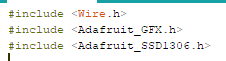
To code and use the OLED, you need to include the libraries #include <Wire.h>, #include <Adafruit_GFX.h>, and #include <Adafruit_SSD1306.h> at the very beginning of the program.
The Wire.h library allows the Arduino to communicate with the screen using the I2C protocol, while the Adafruit libraries provide the built-in functions needed to draw text, shapes, and handle the menu layouts for the game.
u can add them through "manage libraries" section in arduino or you can use these links to download them : (https://github.com/adafruit/Adafruit-GFX-Library).
OLED Display — Showing the Game Output
To set up and use the display, I referenced the Arduino Project Hub tutorial "OLED Display Interfacing with Arduino" by Jobit Joseph (https://projecthub.arduino.cc/jobitjoseph/oled-display-interfacing-with-arduino-263cef), which demonstrated how to wire a I²C OLED
Adafruit_SSD1306 display(128, 64, &Wire, -1);
display.begin(SSD1306_SWITCHCAPVCC, 0x3C);
The 128, 64 sets the resolution, &Wire connects it over I²C, and 0x3C is the I²C address of the display module. The -1 tells the library there is no hardware reset pin in use.
From there, I wrote a custom helper function called drawText() to avoid repeating the same three Adafruit GFX calls every time text needed to be displayed:
void drawText(int size, int x, int y, String text) {
display.setTextSize(size);
display.setCursor(x, y);
display.print(text);
}
Every screen in the project follows the same four-step pattern — clear, set color, draw, push:
display.clearDisplay();
display.setTextColor(SSD1306_WHITE);
drawText(2, 0, 15, "COVER LDR");
display.display();
For example-
display.clearDisplay();
display.setTextColor(SSD1306_WHITE);
drawText(2, 0, 15, "COVER LDR");
drawText(2, 0, 35, "TO PLAY!");
display.display();
This kept the code clean and non-repetitive, since drawText() is reused across every single.
THROUGH THIS, I WAS ABLE TO DISPLAY WHATEVER TEXT I WANTED.
Binary Battle — Game Logic
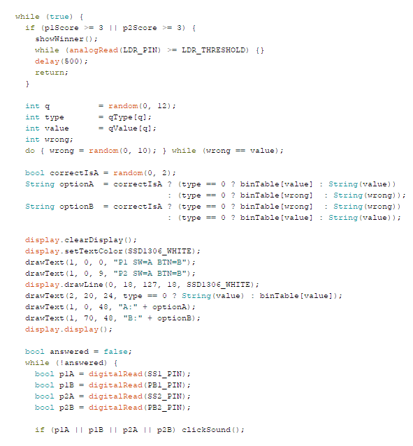
inspiration from : https://www.instructables.com/Arduino-Uno-Quiz-U8G2-Library (however he used keypad and has different code type.
The binary battle game is a two player competition where players race to correctly convert between binary and decimal numbers. The game logic is built around two parallel arrays that store all 12 possible questions:
int qType[12] = {1, 1, 1, 1, 1, 1, 1, 1, 1, 1, 0, 0};
int qValue[12] = {0, 1, 2, 3, 4, 5, 6, 7, 8, 9, 3, 9};
random(0, 12) picking the question
qType[] and qValue[] arrays storing the questions
correctIsA randomly placing the correct answer as A or B
optionA and optionB building what gets displayed on screen
The while (!answered) loop waiting for any of the four inputs — p1A, p1B, p2A, p2B
clickSound() firing the moment any input is detected
handleAnswer() being called to handle scoring
void handleAnswer(int player, bool correctIsA, bool pressedA) {
bool correct = (pressedA && correctIsA) || (!pressedA && !correctIsA);
if (correct) {
if (player == 1) p1Score++; else p2Score++;
correctSound();
} else {
if (player == 1) p2Score++; else p1Score++;
wrongSound();
}
showPointWon(player, p1Score, p2Score, correct);
}
If a player answers correctly they gain a point. If they answer wrong, the point goes to their opponent. The first player to reach 3 points triggers showWinner() which displays the winner and plays the win sound. The game then waits for the LDR to be uncovered to restart.