Interactive Fiber Optic Coffee Table Top
by racinea64 in Workshop > Furniture
94 Views, 1 Favorites, 0 Comments
Interactive Fiber Optic Coffee Table Top
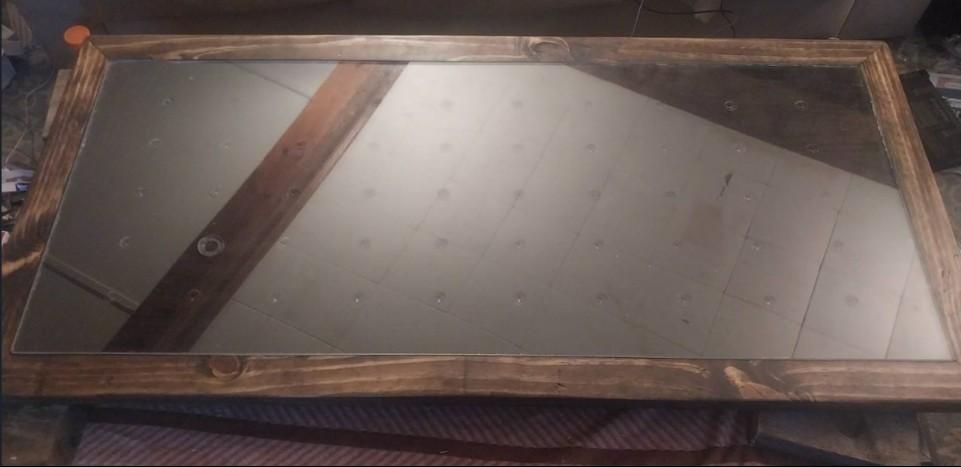
Here i have built an object reactive coffee table top, it involved woodworking, circuitry, fiber optics, arduino coding and ALOT of learning on my part to complete.
i made this coffee table because my girlfriends birthday is coming up and she was scrolling through Facebook reals and she came across this obviously ai generated video of a product like this and said "baby can you make me one of these?" and well thats wiere this adventure started
Supplies
materials needed to complete this project are,
wood, this is pretty flexible as to how you design your table top, whats important is that the mane table section has a 3/16" raised boarder around it for the plexiglass inlay, this table was designed as a 18.5x 44in main table top with a 2 inch boarder making the complete coffee table 22.5x 48 in in total however the exact measurements are not super critical. i suggest keeping your main table dimensions divisible by 6 and 11 for length and width it will make your life easier, i will explain in detail later.
1-12ft length of 1x12 finished pine wood
2-8ft length 2x4 rough cut wood
2- 8ft length 1x3 finished pinewood
9- biscuit jointer biscuits
wood glue
1- 24x48x1/4 plexiglass sheet,
1- 14x20 pcb project board
2- 10x24 pcb project boards
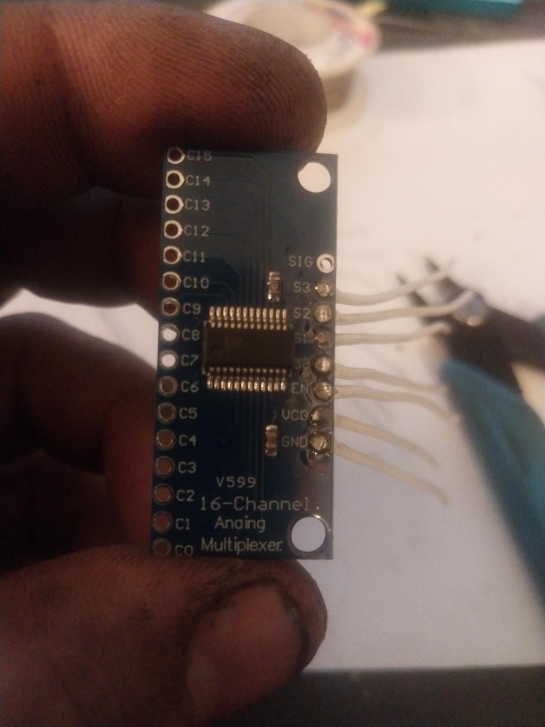
8- CD74HC4067 multiplexer boards (MUX boards)
1- Arduino nano
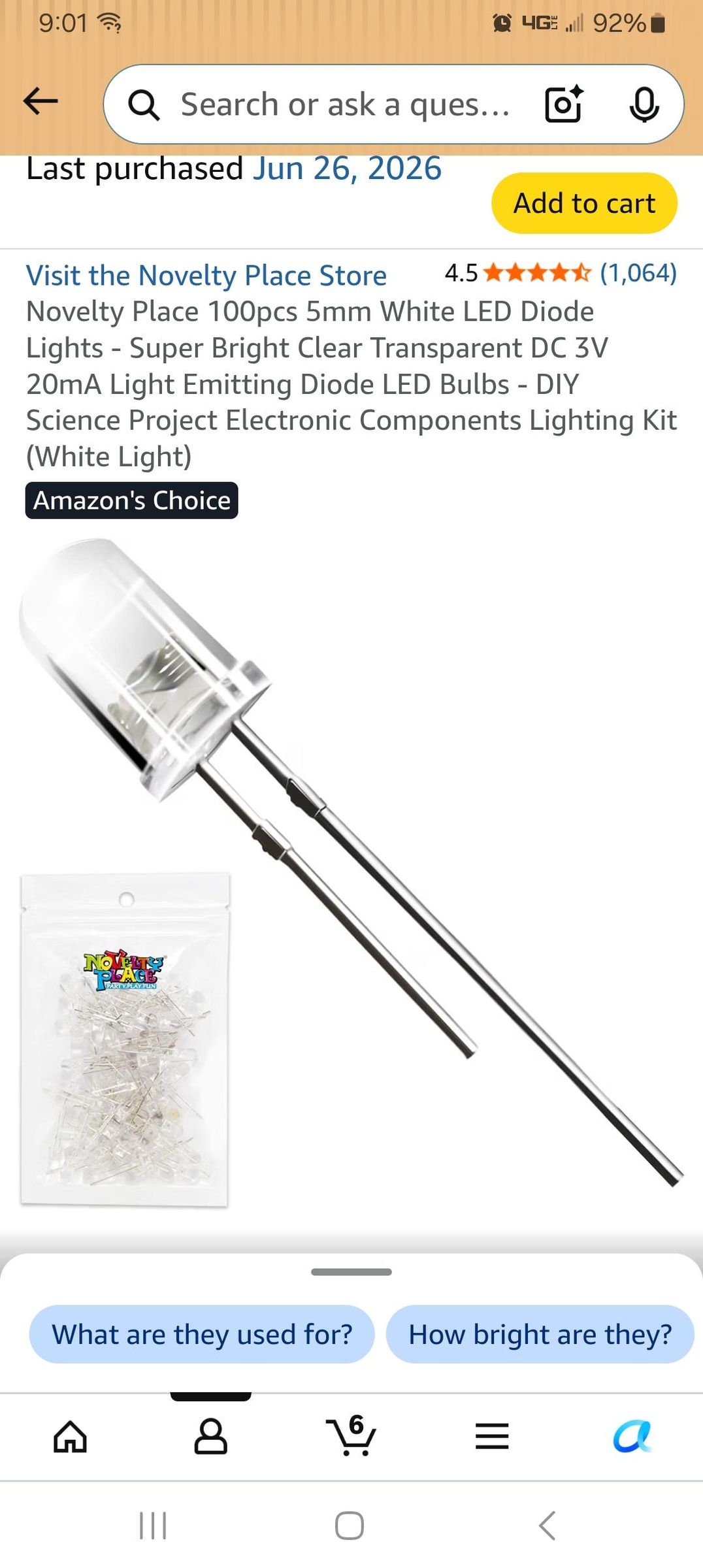
50- ultra bright 5mm leds
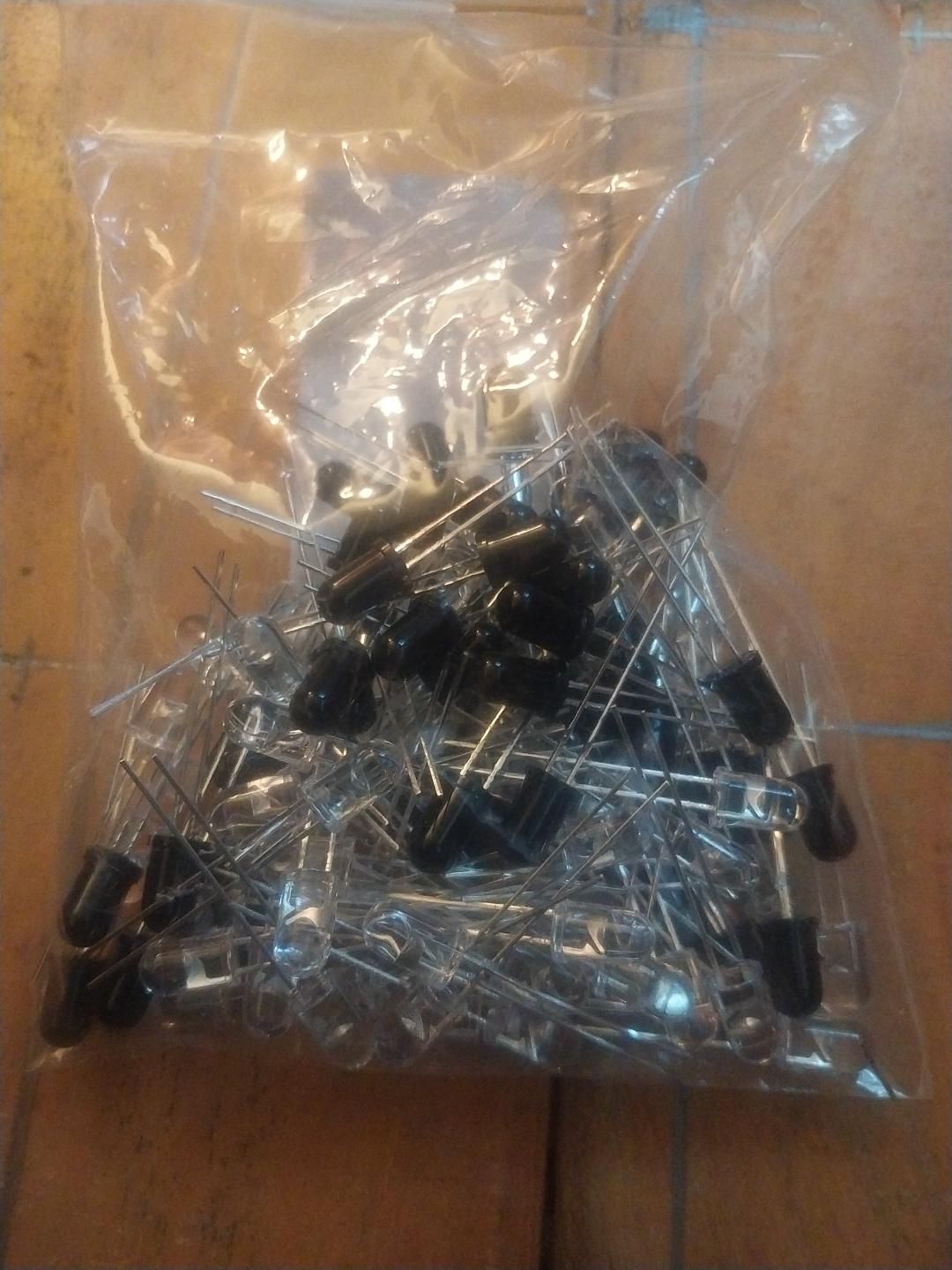
50- IR emitters and receivers (these can be purchased in sets from amazon, i suggest buying 2 packs of 50 because they can be inconsistent)
50- SMD MSOP8/SOP8 to DIP adaptor plate and converter breakout boards (optional)
1- 2 pole DIP switch
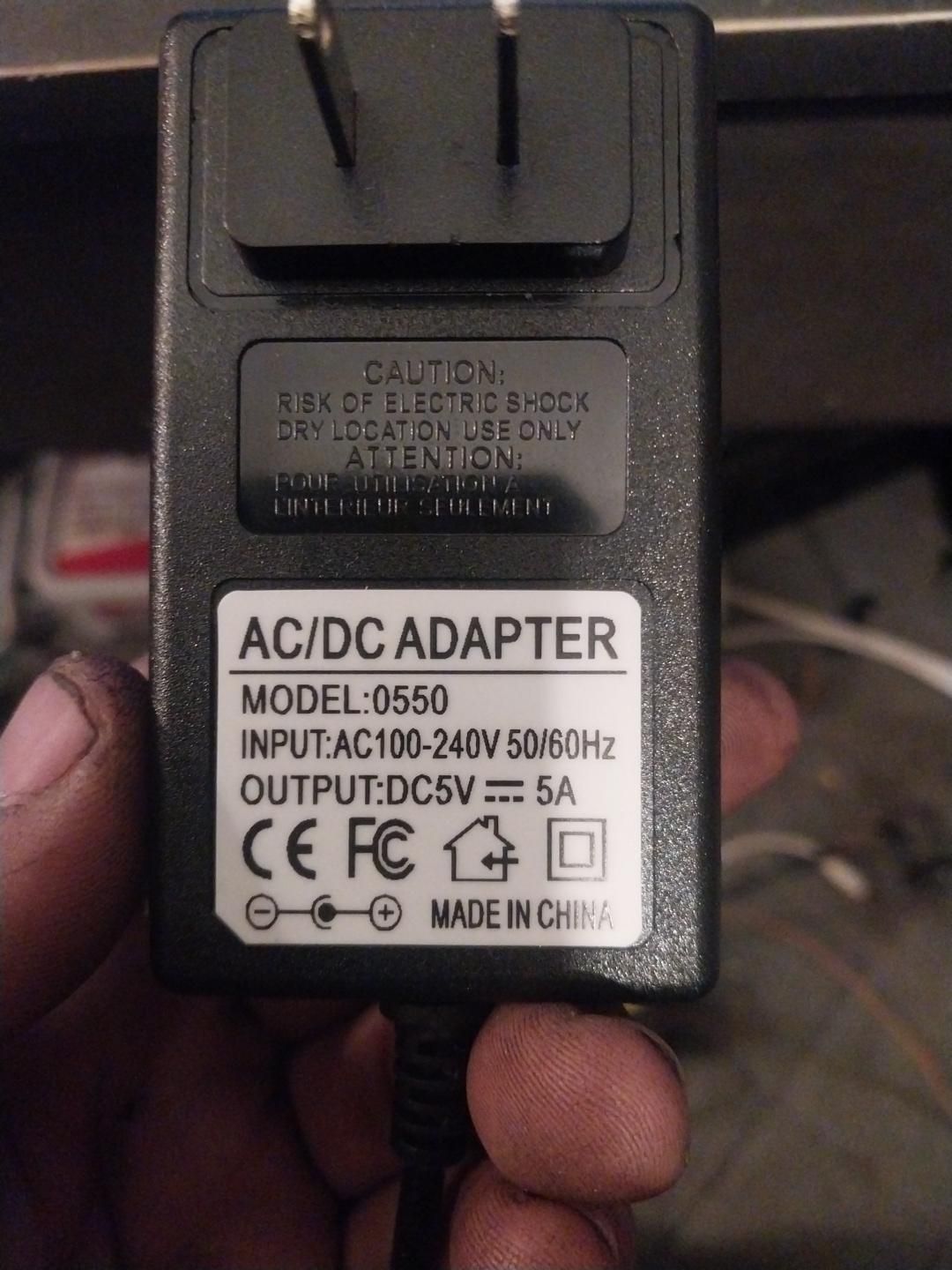
1- 5v 5a power supply (pictured)
1- power plug matching your selected power supply (5mm x 2.3mm used in this project)
estimated 600ft of 26g wire in several colors
estimated 20ft 20 ga wire
1- pack of .5, .75, or 1mm fiber optic starlight cables (100pk of 2m pieces) .5mm used in this project
100- 100 ohm resistors
3- 10k ohm resistors
9- .1uf capacitors
1-role of abs or pla filament
your choice of wood stain
1- can of gloss black spray paint
Wood Working
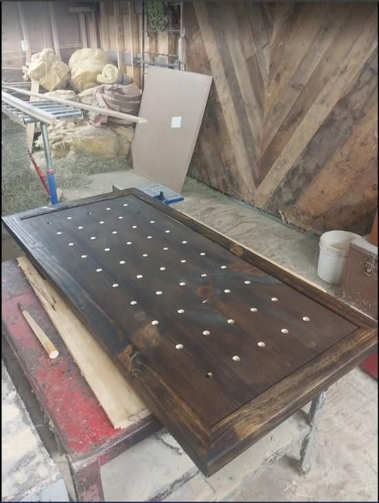
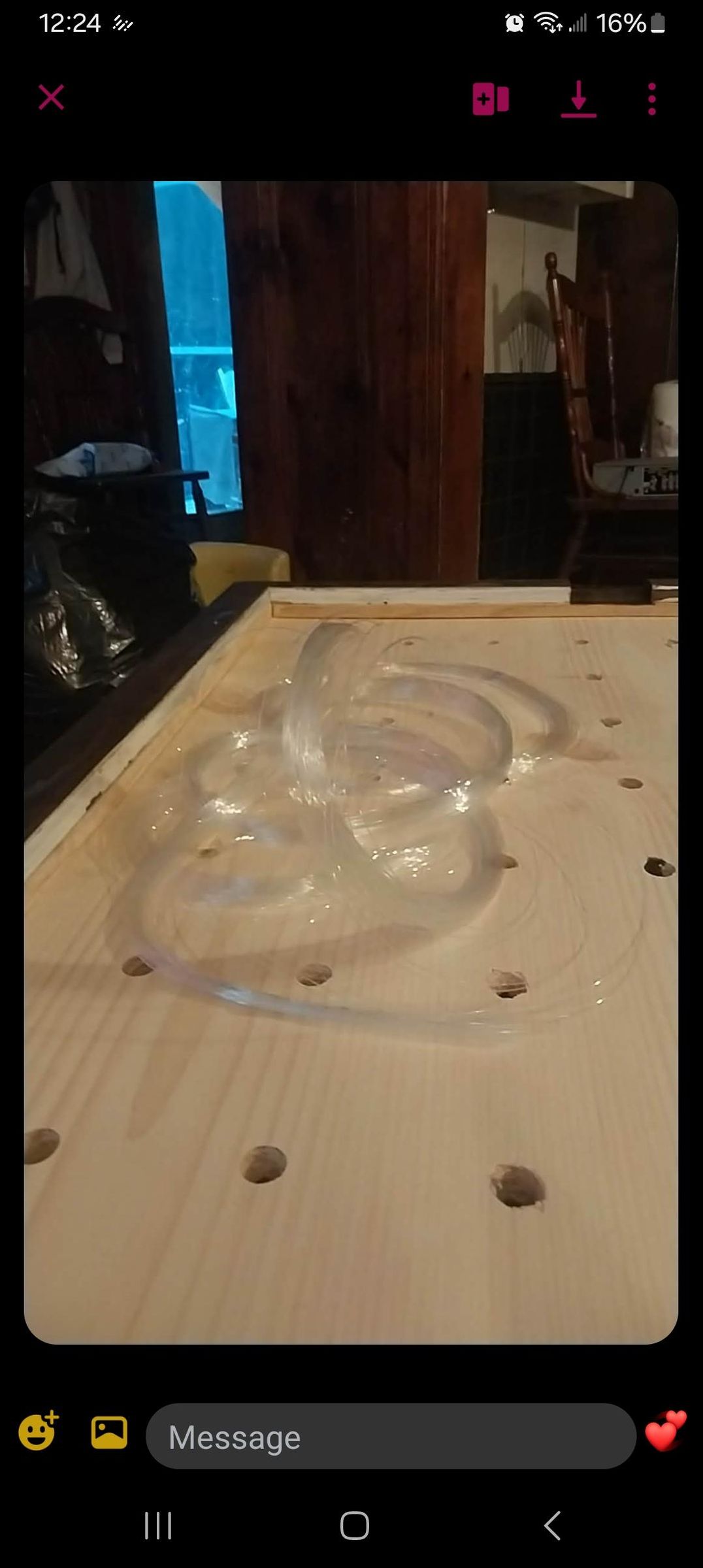
start by making the main sensor and fiber optic body by cutting the 1x12 finished pine wood in half and join the 2 halves together using at least 5 biscuits making 1 flat panel 24in by 6ft, after the glue has dried, cut the panel to your desired size, my sensor body measured 44"x 18.5".
next mark and drill 50, 5/8 in holes in a grid pattern evenly spaced 5 high and 10 long, by taking your sensor bodies width and dividing by 6 and your sensor bodies length and dividing by 11, be careful to drill from the top down as to not blow out the top surface with the drill bit.
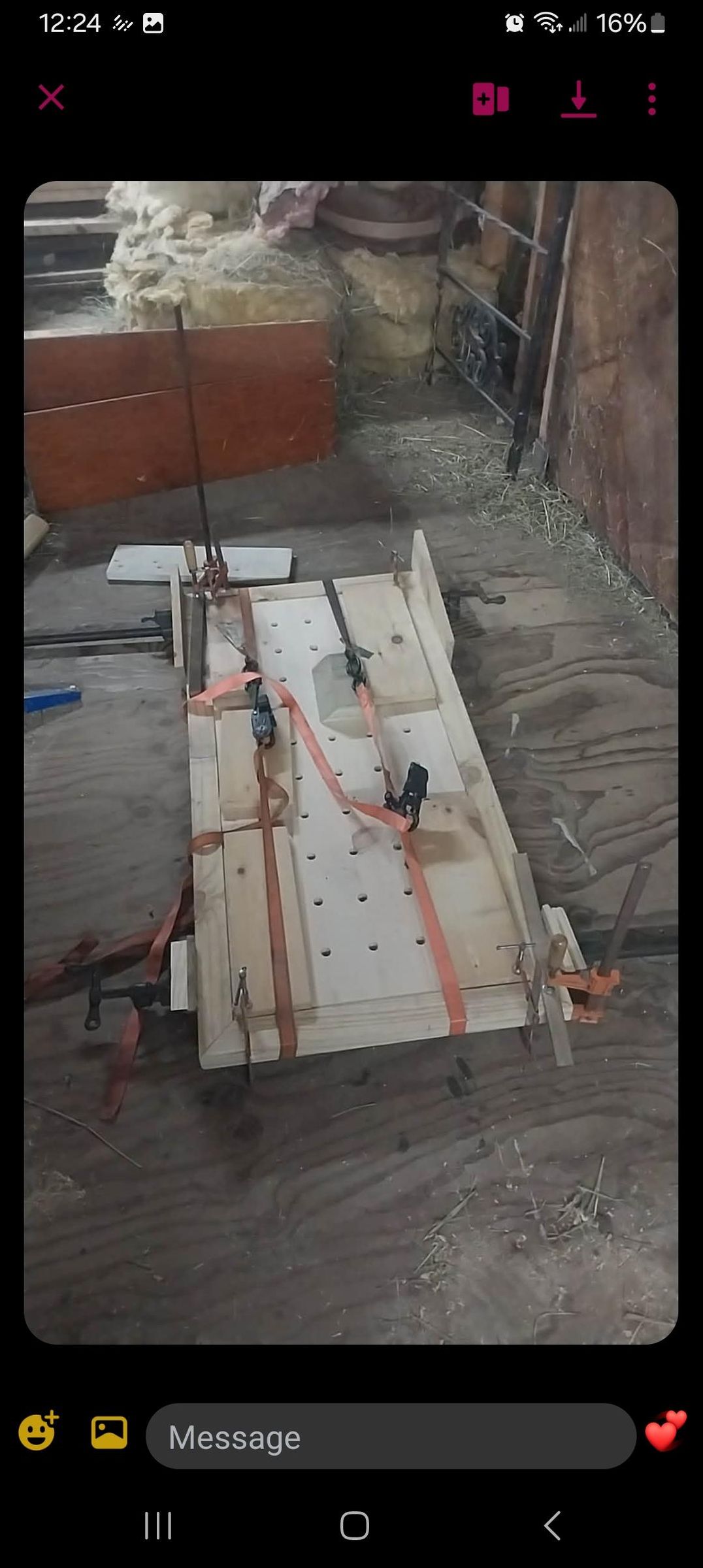
next, with the 2x4 rough cut, build a boarder with an outside dimension that is 4 inches larger then both the length and width of your sensor body by cutting 4, 45 degree joints and using a biscuits to join them as if you were building a picture frame, but DO NOT GLUE TOGETHER YET. On the INSIDE EDGE of each of the boarder pieces, cut a shelf into the boarder pieces to allow the sensor body to sit recessed into the boarder by at least 3/16" but do not allow the shelf to extend under the sensor body by more then 1/4". rip any excess off with a table saw, now glue the frame to the table, i used ratchet straps and several clamps to ensure the sensor body stays pressed down into the shelf as the glue dries over night.
next build a second picture frame with the 1x3 finished pine that has an INSIDE DIMENTION that is the same as the INSIDE DIMENTION of the BOTTOM SIDE of the picture frame that you finished gluing to the sensor body the previous day, however leave a 3 inch gap in the middle of one of the short sides of this picture frame, this can simply be attached with glue and finish nails, aligning the inside edge of this frame to the inside edge of the larger frame however be sure not to use nails that will go though to the top surface.
once the glue has dried, router your desired radius on only the outside of the larger rough cut frame, sand smooth and stain, note I did not radius the top because I wanted a sharper look, I just used 180 grit sand paper to knock off the sharp edges. stain THE FRAMES ONLY this is a mistake i made, DO NOT stain the top of the sensor body, we will be painting that black later but NOT NOW.
The table top woodworking is now complete
Building the Sensors
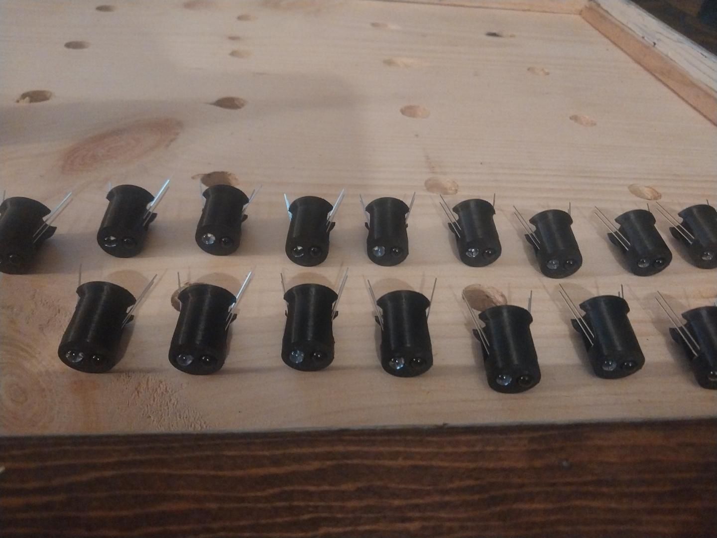
3d print 50 duel sensor angled sensor housings
for each sensor housing, insert 1 IR emitter and 1 IR receiver into the holes of each housing ensuring that the cathode of BOTH is orientated toward the dash on the sensor housing and secure with a dab of super glue ON THE BACK SIDE of the emitter and receiver
(optional step) solder 1 SMD MSOP8/SOP8 to DIP adaptor plate and converter breakout board to the IR led pins ensuring nothing is connected together try to push the board as close to the back of the sensor body as possible and trim the extra leads off with wire cutters.
repeat for all 50 sensors
Downloads
Building the LED Bars
print 5 led mount bars
each led mount bar holds 10 standard 5mm LEDs, however before inserting the leds drill out the small holes in the front face of all 10 led holes so that a bundle of 15 fiber optic cables fits slightly loosely in the hole, this will take some trial and error and will depend on the size of fiber optic cable you chose.
next chamfer the small holes with a chamfering bit.
next, insert 1 led into each of the 10 holes from the back side, be sure to orente the cathode of all the leds toward the bottom and the anode toward the top, and secure using a dab of super glue on the back side of each led.
next, cut a piece of 20 gauge black wire about 2 inches longer then the length of 1 led bar, and strip all the casing off it, lay the 20 gauge wire into the long channel on the back, bottom of the led bar housing, bend the cathodes down inth their respective channels and solder ALL led cathodes to this wire.
next place 10 100 ohm resistors in the channels that are cut into the top of the led bar housings and secure with a dab of super glue. bend the anodes of the leds up into their respective channels and solder the anodes to each of the resistors and trim excess led/ resistor leg with flush cutters, leaving the other end of the resistor long for now.
repeat for the other 4 led bar housings
Downloads
Drilling Fiber Optic Holes
this next step may be daunting.
using a micro drill, drill 750... yes you read right, 750 holes from the top side of the sensor panel. the size of the drill bid will depend on your choice in fiber optic cable, you want to use a drill bit that is about .25mm LARGER then your choice in fiber optic cable
each sensor will have 15 individual stars that it will be controlling so around each of the 5/8 holes randomly drill 15 holes all the way through the table top to the back side
if you are regretting this project i understand but the final results are worth it trust me.
Build the Power and Switch Mount
3d print the power selection plate, and insert the power jack facing toward the inside of the L shape, secure this to the bottom of the large frame inside the 3 inch gap that you left in the smaller frame.
secure the dip switches to the power housing using super glue, be sure to face the switches and the power plug facing the same way.
there, an easy step after drilling 750 tiny holes
Downloads
Place the Sensors and Led Housings
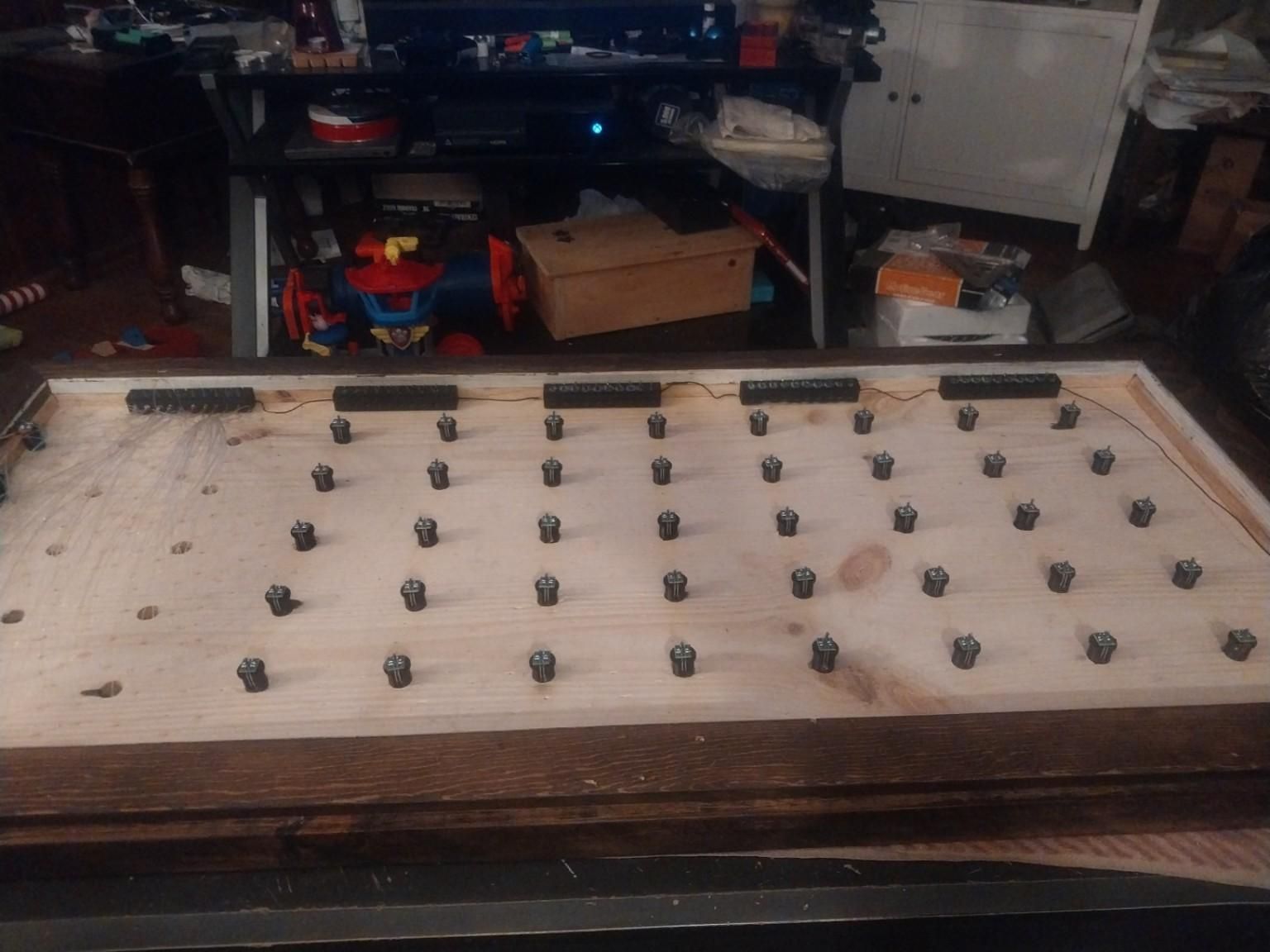
secure the led housings on one of the long edges directly on the under side of the sensor panel using super glue as pictured be sure that the back of the leds is up against the inside of the larger frame, also be sure that the wire that you soldered the CATHODES to is sticking out of both sides of each sensor, youll need this for wiring later.
next press a sensor into each of the 5/8" holes from the bottom up but do not press them all the way to the shelf on the sensor body you may need to tap the back side with a hammer and punch to get them to press into the holes, if so tap on the plastic not the board if you chose to use them
wising a straight edge, tap each sensor into the hole until the IR emitter and receiver tips are as close to flush with the top of the sensor panel as possible. secure with super glue if necessary. be sure NOT TO PRESS THE SENSOR HOUSINGS ALL THE WAY THROUGH THE WOOD as it will cause the top surface to chip out
Building the Maine Control Board
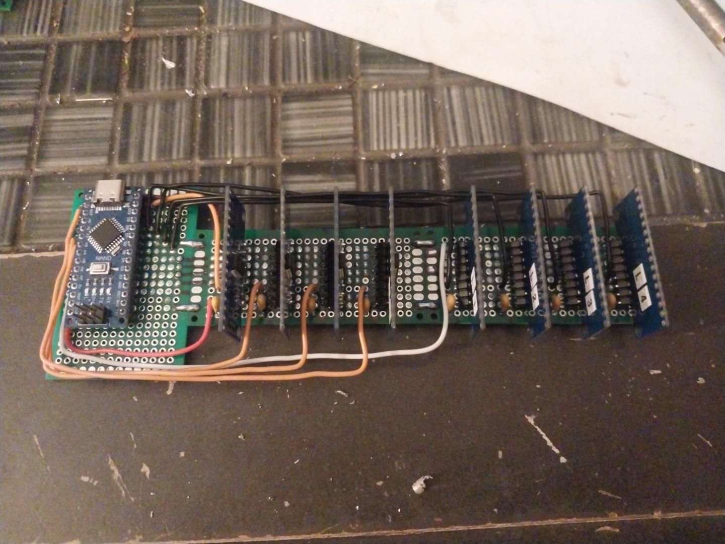
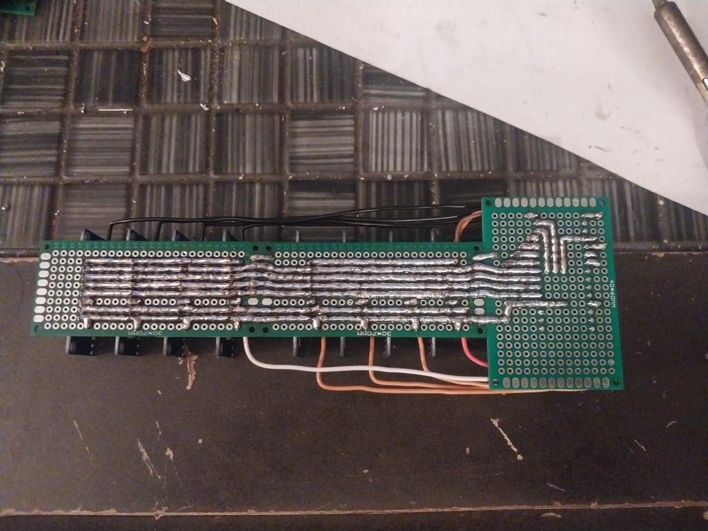
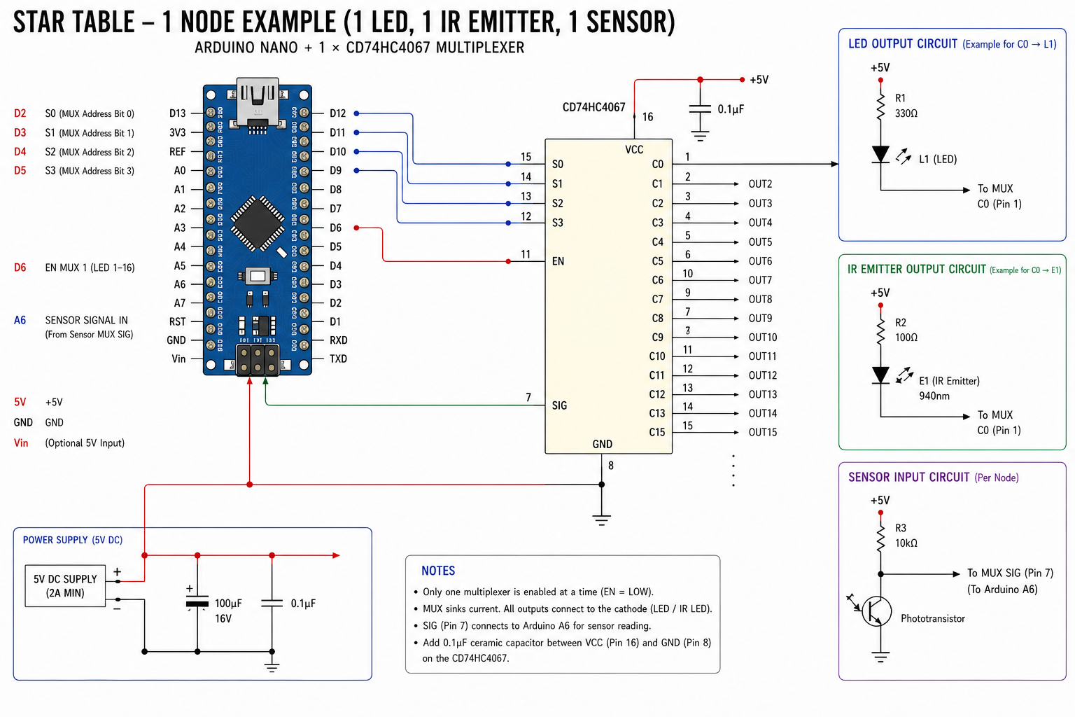
i will update this section later with a schematic of the entire circuit but the 2 pictures in this step show the gist of it, i built the main board using solder traces and jumper wires where needed, i placed my pull down resistors for the sensor mux board input and the dip switches underneath the Arduino board freeing up some space for the all the wiring that will eventually need to run directly to the Arduino
For the firmware to work without modification the Arduino inputs and outputs need to match mine, however if you are a decent coder you can modify your inputs and outputs to lay out the board as you see fit, you will end up needing 1 analog input shared by all 4 sensor MUX boards with a 10k pull down resistor, 4 separate enable pins for each of the sensor MUX boards, 1 digital output shared by all 4 LED MUX boards, 4 separate enable pins for each of the LED mux boards, and 2 digital inputs for the 2 poll dip switches with 10k pull down resistors on each of those.
Be sure to tie all powers for the Arduino and mux boards together, and all grounds for the Arduino and mux boards together, this will make things a bit easier later.
for each of the 8 mux boards and the Arduino, put a .1uf capacitor between the power and ground of each board to supply each board with its own power buffer.
this section will be updated with much more detail soon i promise
Wiring
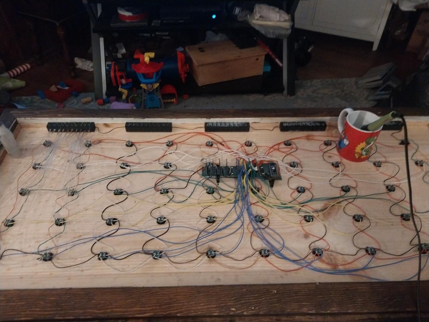
this will be the most time consuming step
the IR emitters are to be wired direct to 5v power. start by running a length of red 20 gauge wire from the power port to the 10 sensor bodies on the opposite side that you placed the led bars. this is important, first a short run from the power port positive to the closest IR SENSOR POSITIVE LEG ONLY, then run 20 ga wire and connect all the positive legs OF THE SENSORS ONLY NOT THE EMITTERS YET, we will handle those later. next run 26 ga wires from the bottom sensor housings to each of the 4 above them eventually tying all the sensor anodes together to power input.
next, connect all the led anodes together by soldering 20 ga black wire to all the led housings and connect that directly to the negative.
next run another black wire to each of the sensor housings, but, this time TO THE EMITTER CATHODES ONLY, eventually tying all emitter cathodes to power negative.
next for each sensor, solder a 100 ohm resistor between the anode leg of the sensor and the anode leg of the emitter.
this is the first thing you can now verify. plug in the power supply and using your phone camera, look at the top of the table, you should see every emitter outputting IR light, its invisible to your eyes but your phone camera can pick up on it and it will convert it to something our eyes can see, cool no?
ok back to wiring, remove the power supply
if you laid out your main board like mine then you will be able to use the board mounts I've supplied, print 2 of the smaller ones and 1 of the larger ones (i cant remember which is which) using super glue pick a place near the center of the bottom of the sensor panel to place your main board be careful to glue the mounts in places that do not cover any of the tiny holes you drilled for the fiber optic cables earlier, if you laid out your board differently you can simply use stand offs but they need to be at least .75" to allow for any fiber optic cables that are beneath the main board to have a smooth bend.
now, run 26 ga wires form each led ANODE (the other side of the resistor on the led bars that we left long earlier) to A SEPERATE OUTPUT ON THE LED MUX BOARDS FOE EVERY LED. i used a different color for the a coelom, b coelom, c coelom, d coelom, and e coelom. You will end up with 10 sets of each color wire this will help keep things organized. 3 mux boards will be completely used and 1 mux board will only have 2 outputs used
next run a 26 ga wire from each of the sensor CATHODES to AN INDIVIDUAL INPUT ON THE SENSOR MUX BOARDS. it is important that the inputs on the sensor boards match the outputs of the led boards, meaning id node a1 (the top most righthand node on the table) has its led on LED MUX 1, C0 then the sensor input for that node MUST BE on sensor MUX 1, C0. if you mess this up the system will be borderline impossible to fix with code.
next run a 26 ga positive and negative to the Arduino and all 8 mux chips.
do not secure the main board just yet
run 26 ga wire from the positive input to 1 side of both the dip switches, and then run another 26 ga wire from the other side of the individual dip switches to each of the Arduino inputs that have the pull down resistors for the dip switches.
i will update with sensor and led pin wiring soon i promise
Mounting Fiber Optics
this is the next most grueling task
for each of the nodes there is 15 fiber optic cables that run from each led to its corresponding sensor, so for node A1, separate out 15 full lengths of fiber optic cable, line up the ends as close as possible and insert the bundle into the small hole of led a1 on the led housing and secure the entire bundle into the led housing using super glue, be sure all fiber optics are securely glued in place before preceding to the next step.
Lay the fiber optics over sensor housing a1 and cut the entire bundle about 5 to 6 inches longer then is needed to reach the 15 holes around that specific sensor housing, however the holes you pick isn't extremely crucial just be sure that each sensor ends up with 15 fiber optic cables running to it. insert 1 fiber optic cable through 1 hole ensuring there is at least 2 inches of fiber optic cable protruding out the top of the table THIS IS CRICIAL.
repeat this process for all 50 nodes ensuring all LEDs and sensor nodes are paired correctly.
after all fiber optics are routed and secured, snap the main board into its holders or secure it using your desired stand offs. the hardest part is done now you can breath a sigh of relief after all that work
Paint and Trim
ONLY AFTER ALL FIBER OPTICS ARE SECURED IN PLACE, mask off the outer frame with masking tape and using the black spray paint, paint the TOP of the sensor panel where the fiber optics are protruding through the table top, don't worry painting the fiber optics that are protruding is what you want, apply 2 to 3 medium coats causing the paint to fill the gaps in the fiber optic cables and the holes they are secured in. allow to dry completely.
next trim all the fiber optic cables flush with the top of the table with a pair of flush cutters (as close flush as possible)
Plexiglass
cut the plexiglass so that it fits tightly inside the large frame and rests directly on top of the sensor panel, this will be your actual table top. it should be the same size as the sensor panel dimensions.
Flash the Arduino and Operating Instructions
The .txt file in this section is the complete Arduino sketch that i developed to run this table. flash this sketch and note there is no power switch, simply plug the 5v power supply in to power the table on and remove to power off
when the table is powered on a ripple will propagate from the center 2 nodes to the outer edges of the table 1 time indicating that sensors are calibrated. next the current mode that is selected on the dip switches will be displayed on the table for 3 seconds.
after the mode display fades out the table enters the current selected mode.
the table has 4 modes that are set with the dip switches near the power plug
mode 1= 00
mode 2=10
mode 3= 01
and more 4 = 11
mode 1: mode 1 small presence mode, if an object is placed over a sensor, that node and only that node will fade to full brightness and then when the object is removed, that node will fade out.
mode 2: in mode 2 when an object is placed over a sensor, that node will fade in and then a ripple will propagate from that node out, if the object is left on that sensor only that node will remain illuminated, until the object is removed, then that node will fade out. .5 seconds must pass before that sensor will trigger another ripple.
mode 3: mode 3 has no sensor inputs, a galaxy of primary nodes are lit at 60% brightness and randomly any node will twinkle
mode 4: mode 4 is large presence mode, when an object is placed over a sensor in mode 4, that node and all immediate surrounding nodes will fade to full brightness, and remain lit as long as an object is placed over the sensor. when the object is removed all 9 nodes will fade out simultaneously.
Idle mode: when the table is in modes 1, 2 or 4 if nothing is on the table for a period of 15 seconds or more, a random node will fade in and then fade out. every 15 seconds until the table has sensed an object being placed on it.
the table features an automatic sensor calibration on start up and MUST be powered on with an empty table, however the IR sensors and emitters i used in this project can be inconsistent to do not be surprised or discouraged if some of the sensors do not work correctly, they simply need to be swapped out. i recommend printing a couple extra sensor housings and building them just in case you end up with a bad sensor or emitter, i had to replace 4 of them when building mine.