Interfacing Soil Moisture Sensor With Arduino
by Rachana Jain in Circuits > Arduino
187 Views, 0 Favorites, 0 Comments
Interfacing Soil Moisture Sensor With Arduino
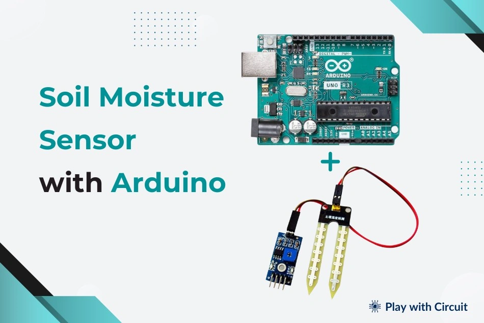
Want to know when your plant actually needs water instead of watering it on a fixed schedule? An FC-28 soil moisture sensor is a simple way to measure how wet or dry the soil is and use that information in an Arduino-based project.
In this project, we will connect an FC-28 sensor to an Arduino Uno, read its analog output, convert the reading into an approximate moisture percentage, and display the result on a 16×2 I2C LCD. We will also test the sensor's digital output and see how to adjust its threshold using the onboard potentiometer.
This setup can be used as the starting point for projects such as automatic plant watering systems, garden monitors, greenhouse controllers, and irrigation systems.
What You Will Learn
- How an FC-28 soil moisture sensor works
- The difference between its analog and digital outputs
- How to connect the sensor to an Arduino Uno
- How to calibrate the sensor
- How to display soil moisture on an I2C LCD
- How to use the digital output for a simple wet/dry indication
- Some practical limitations of resistive soil moisture sensors
Supplies
For this project, you will need:
- Arduino Uno R3
- FC-28 soil moisture sensor
- FC-28 sensing probe
- 16×2 I2C LCD
- Breadboard
- Jumper wires
- USB Type-A to Type-B cable
- Arduino-compatible power supply
- Arduino IDE
How the FC-28 Soil Moisture Sensor Works
The FC-28 is a resistive soil moisture sensor. Its probe has two exposed conductive tracks that are inserted into the soil.
The electrical resistance between these conductors changes depending on the amount of water present in the soil. Moist soil generally conducts electricity better, resulting in lower resistance. Dry soil has poorer conductivity and therefore produces higher resistance.
The sensor module converts this change into an electrical signal that can be read by the Arduino.
The FC-28 module typically operates from 3.3 V to 5 V and provides both analog and digital outputs.
Important: The moisture percentage calculated from an FC-28 is an approximate relative reading. It is not the same as laboratory-measured volumetric water content unless the sensor has been properly calibrated for a particular soil type.
FC-28 Hardware Overview
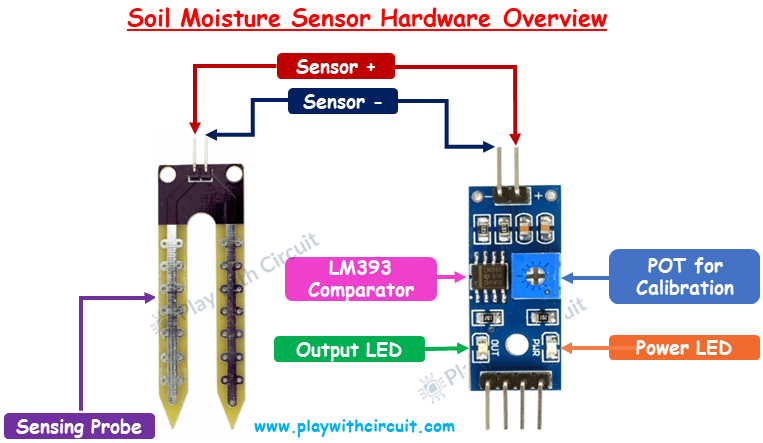
The FC-28 setup consists of two main parts:
1. Sensing Probe
The fork-shaped probe is the part that goes into the soil. It contains two exposed conductive surfaces.
When inserted into soil, the electrical resistance between these conductors changes with soil moisture. A two-pin connector allows the probe to be connected to the sensor module.
2. Sensor Module
The small interface board processes the signal from the probe and provides analog and digital outputs.
Important components on the module include:
LM393 Comparator:
The LM393 is used to compare the sensor voltage with an adjustable reference voltage. This comparison generates the digital output.
10 kΩ Potentiometer:
The onboard trimpot controls the threshold used by the comparator. Turning it changes the point at which the digital output switches between HIGH and LOW.
Power LED:
This LED indicates that the module is receiving power.
Output LED:
The second LED indicates the state of the comparator output.
FC-28 Pinout
The module normally has four pins:
- VCC: Power input, typically 3.3 V or 5 V
- GND: Ground connection
- AO: Analog output
- DO: Digital output
The AO pin provides a continuously varying voltage that can be measured using an Arduino analog input.
The DO pin provides a simple HIGH/LOW signal according to the threshold set by the potentiometer.
Analog vs Digital Output
The two outputs are useful for different applications.
Analog Output
The analog output is useful when you want more information about the moisture level.
For example, the Arduino can read the sensor using analogRead() and use the resulting value to estimate a moisture percentage.
This approach is better for applications where you want to display moisture levels or control watering based on several moisture ranges.
Digital Output
The digital output works more like a switch.
The LM393 compares the sensor signal with the reference voltage set by the potentiometer. Depending on the threshold, the output changes state.
This is useful when the project only needs to determine whether the soil is dry or sufficiently moist.
Calibrating the FC-28 Sensor
Calibration is important because different soils can produce different readings.
Follow these steps before using the sensor in your project:
- Place the probe in dry soil.
- Observe the output LED.
- If necessary, rotate the potentiometer counterclockwise until the desired switching point is reached.
- Place the probe into wet soil.
- Check the output LED again.
- Slowly adjust the potentiometer until the digital output changes at the moisture level you want.
The exact direction and threshold can vary between module versions, so it is better to observe the LED/output while adjusting the potentiometer rather than relying only on the direction of rotation.
For an analog moisture percentage, record readings from known dry and wet conditions and use those values as calibration points in your Arduino program.
Connecting the FC-28 to Arduino Uno
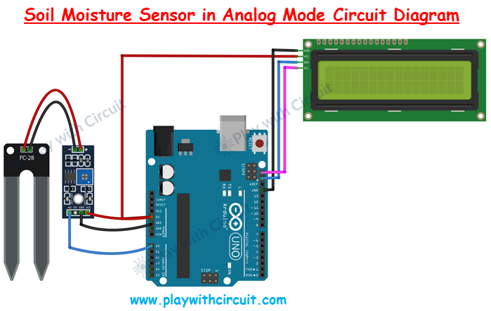
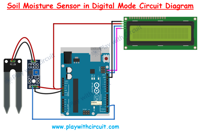
For the analog experiment, make these connections:
FC-28 → Arduino Uno
- VCC → 5V
- GND → GND
- AO → A0
For the I2C LCD:
- VCC → 5V
- GND → GND
- SDA → A4
- SCL → A5
The Arduino Uno uses A4 for SDA and A5 for SCL on the standard Uno R3 pinout.
Conclusion
The FC-28 is an inexpensive and beginner-friendly sensor for experimenting with soil moisture monitoring. By connecting its analog output to an Arduino Uno, you can obtain a variable reading and convert it into an approximate moisture level. Its digital output provides an even simpler way to detect whether the soil has crossed a selected threshold.
Although the FC-28 is useful for learning and small projects, remember that it is a resistive sensor, so probe corrosion and calibration can become important for long-term use.
With the basic Arduino circuit working, you have everything needed to move toward a more practical automatic plant watering or smart irrigation system.
For source code visit Play with Circuit (playwithcircuit.com)