Intro to NI Multisim 12.0 Circuit Simulator
by Rajkumar2506 in Circuits > Electronics
13243 Views, 12 Favorites, 0 Comments
Intro to NI Multisim 12.0 Circuit Simulator
National Instruments Multisim 12.0 is a circuit simulator.The advantage of using this simulator is that you can add the tolerance value to components.Gendrally circuit simulators has zero tolerance.So there is variation in actual practical value and simulated value.This Problem is over come by NI Multisim by the use of adding tolerance value. The Multisim had all standard components such as resistors,Capacitors,Inductors,Transformers,OP-AMP,TTL,CMOS,Micro Processor,Controllers etc.
Installing the NI Multisim 12.0


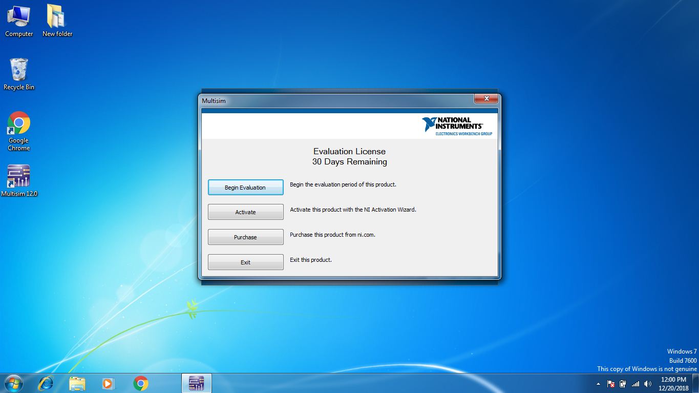


NI Multisim 12.0 gives 30 days trial use of software.You can extend this period to 2 years if you follow the installation method given below.I had also given the installation steps in picture given above.
Installation Method
- Change the system date from 2016 to 2018.
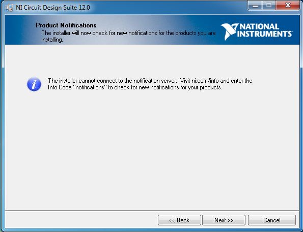
- Disconnect your internet connection.
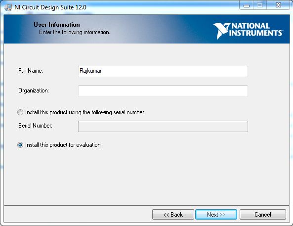
- Click on setup in your downloaded NI software.evaluation
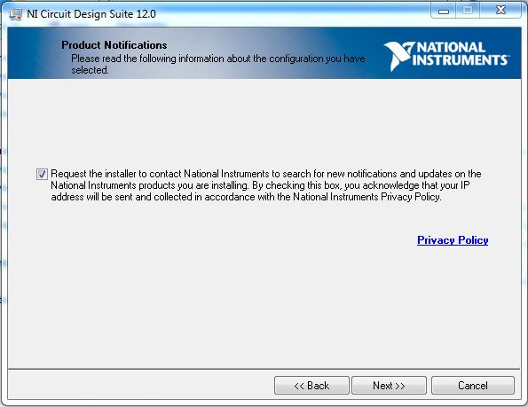
- click on install this product for evaluation then click next>>
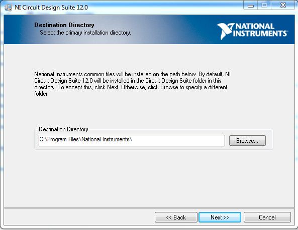
- Set your Destination Directory for installation and click on next>>
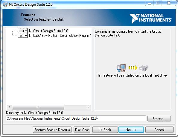
- Then click next>>
- Then click next>>
- Then click next>>
- Click on I accept Lisence agreements and then click next>>
- Then click next>>
- After that the installation will start.
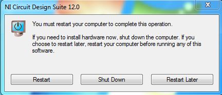
- After the installation is complete click next>>.
- Then click Restart to complete your installation.
- After Restart follow the below steps
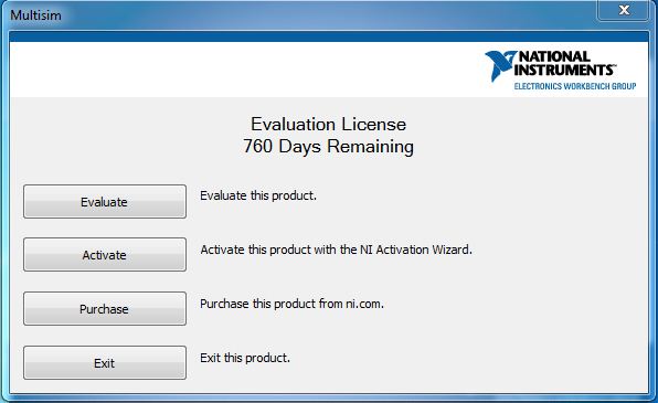
- Go to start-->All Programs-->National Instruments-->Circuit Design Suit-->Multisim.
- Click on Evaluate.This will open your multisim simulation software.
- Then close the multisim.
- Now change the year from 2018 to 2016.
- Then open your Multisim Software,Now you have got 2 years trial period of use.
- Now you have finished your installation.
Opening a New File

- Open your multisim software
- click on File-->New-->Design
- Now you have created your new workspace.
Customize the Workspace
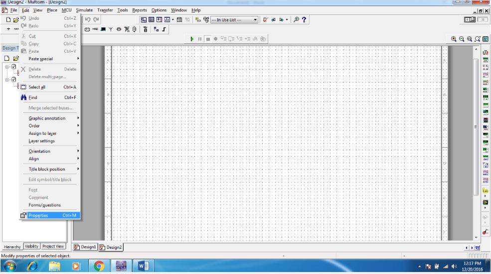

If the larger circuits has to be simulated you need more workspace.You can change the size of your workspace depending on the size of circuits.
To change your size of workspace
- Click on Edit--> Properties.This will open up a window called sheet properties.
- On sheet properties click on workspace.
- Now you can change the size of your workspace.
Customize the Toolbox and Toolbars
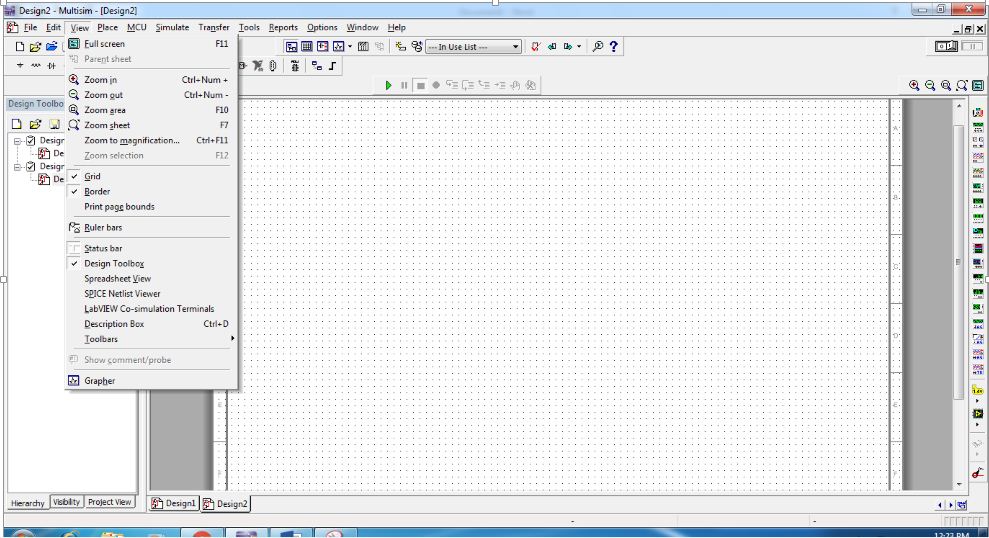
To Customize your toolbox.
- click on view.
- Here you can enable or disable the Grid,Border,Design toolbox.
To customize your toolbars.
- click on View-->Toolbars.
- Here you can customize what component toolbars you want to have in front.
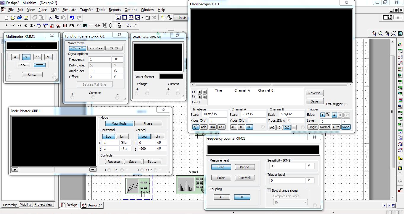
Instruments Toolbox
The toolbox you see on your right hand side is a Instruments toolbox.It contains equipments such as
MULTIMETER
- It is used to measure VOLTAGE and CURRENT of AC and DC Signals.
WATT METER
- It is used to measure the power of your circuit.
FUNCTION GENERATOR
- It is used to generate different waveforms with different frequency.
- Wave forms such as Sine,Triangular,Square Wave.
OSCILLOSCOPE
- It is used to see the output wave form of Circuits.
BODE PLOTTER
- This plot is used in CONTROL SYSTEM ENGINEERING to see damping ratio.
Frequency Counter
- Imagine you have created oscillator circuit.To see the frequency of oscillator circuit you can use frequency counter
WORD GENERATOR
- This will generate words randomly which can be used in encoding technique to secure the data being transmitted.
IV ANALYZER
- IV analyzer is used to measure the parameters of transistor circuits.
- It measures the IV characteristics of transistor.
- I stands for Current.
- V stands for Voltage.
Distortion ANALYZER
- It will analyze how much distortion taking place in your circuit.
- Distortion will arise due to power fluctuation,Interference caused due to placing of different components.
SPECTRUM ANALYZER
- This will analyze the frequency spectrum of signals.
Placing the Components in Workspace
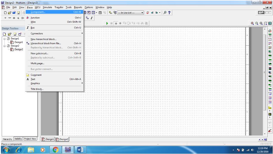

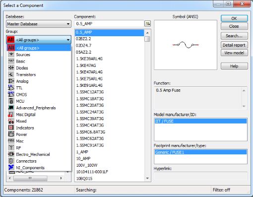
To get components
- click on -->place-->components
- This will open up components window.
- On left side click on All groups to display all components details
- Select the component click OK and then place the component in workspace.
Connecting the Two Components

- Simply click on the terminal of component.
- This will create wire automatically.
- Then with the wire create drag the wire to other component terminal then click on it.
- This will connect your two components.
Drag and Dropping the Instruments From Toolbox

- On your right hand side there will be a toolbox.Which is instruments toolbox.
- Simply drag and drop the Instruments to workspace.
- After dragging the instruments,double click on it.It will give the detailed pannel.
Adding Tolerance to Resistor

Gendrally many circuit simulator have zero tolerance value to resistor.But in Multisim you can add tolerance to Resistor.The 4 band resistors that we are using have GOLD band at last which implies the resistor have + or - 5% of tolerance.
To add tolerance to resistor
- Drag and Drop the resistor to workspace.
- Double click on the Resistor.This will open up a window.
- On that window you can add tolerance to resistor.
Analyse the Different Parameters of Circuit
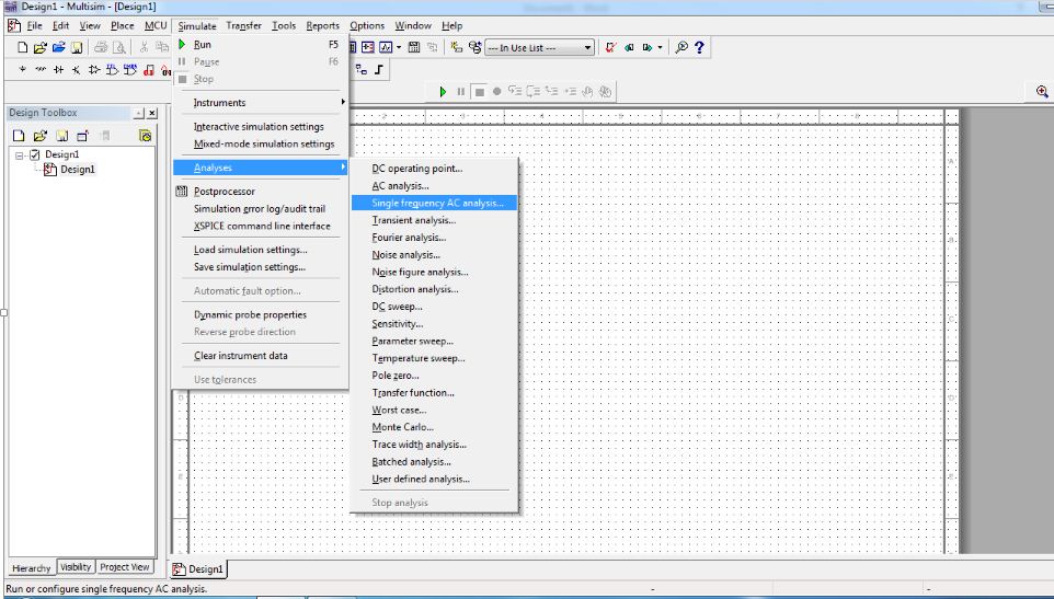


You can perform many types of analyses on your circuit components.This analyses will give reports in GRAPHICAL REPRESENTATION.The analyses such as follows
- DC operating point
- AC analysis
- Transient Analysis
- DC sweep
- Sensitivity.
To go to analyses
- Click on Simulate--->Analyses.
For Example
I have analysed the TRANSIENT ANALYSES of Variable Voltage Regulator Circuit
Simulating the Circuit
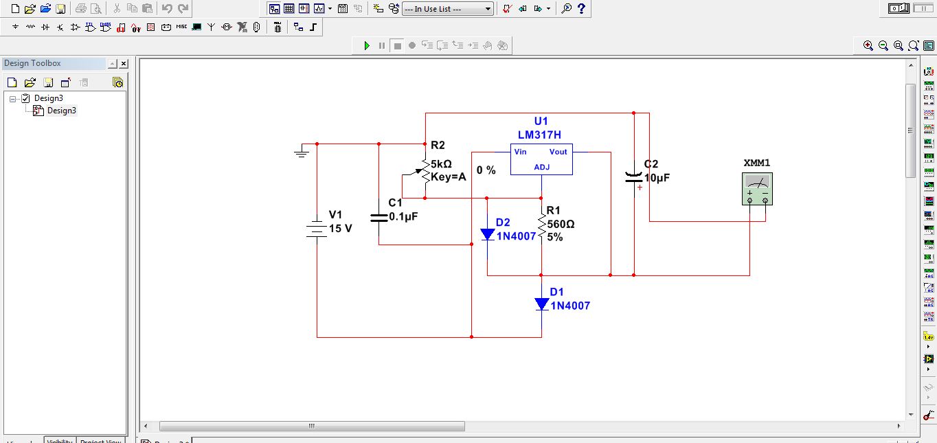

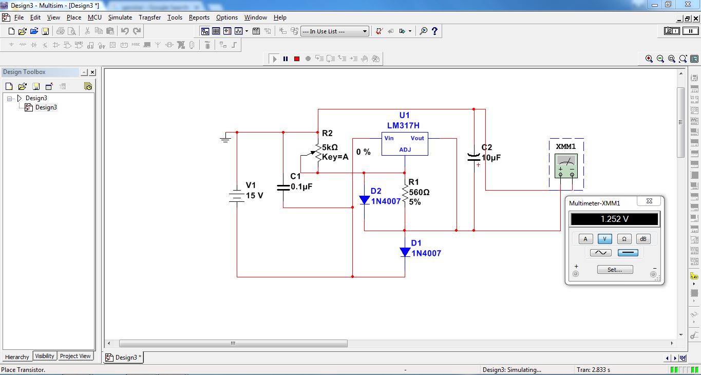

I have used Variable Voltage Regulator Circuit for simulation
To simulate the circuit
- Click on simulate-->Run or you can just click on Play button which is just above the center of workspace.
- You can also use F5 key to simulate..