JLCMC Split Aluminum Enclosure for Custom Electronics Projects
by anamaspoty in Circuits > Arduino
244 Views, 1 Favorites, 0 Comments
JLCMC Split Aluminum Enclosure for Custom Electronics Projects

Project Overview: Transforming an Aluminum Enclosure into a Tech Fortress
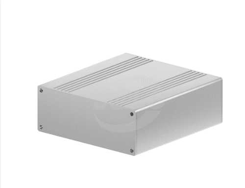
In this hands-on project, I’m going to show you how to create a custom electronics project housing using the versatile Split Aluminum Enclosure from JLCMC (W106 H40 L110mm). This enclosure is the perfect choice for those who need something durable, sleek, and practical for protecting a variety of electronics projects.
Whether you're building an Arduino-based sensor, a small robotics system, or any other custom electronics, this enclosure is a great option for turning your tech idea into a stylish, functional, and protected device. Not only will I walk you through the steps of customizing this enclosure to fit your project, but I’ll also show how to integrate heat sinks, brackets, and other components, all available on JLCMC, to take your project to the next level.
Why the JLCMC Split Aluminum Enclosure?
The JLCMC Split Aluminum Enclosure isn’t just another generic case—it’s a purpose-built, high-quality housing designed for makers, tinkerers, and engineers who want a durable, professional-looking finish for their projects. With the split design, it’s easy to access your electronics once they’re installed, and it’s made from anodized aluminum, giving you both protection from external factors and a sleek look.
Please check more here: https://jlcmc.com/?from=Ana
Here you can also find the code base work on my profile: anamaria1-png/JLCMC-Split-Aluminum-Enclosure-for-Custom-Electronics-DIY-Projects and on JLCMC Split Aluminum Enclosure for Custom Electronic Project - Hackster.io
And also you can check more about me and my DIY work: (31) JLCMC Split Aluminum Enclosure for Custom Electronics Projects | LinkedIn
Supplies


What You’ll Need
Before we dive in, here’s a list of materials and tools you’ll need to get started:
Materials:
- Split Aluminum Enclosure (W106 H40 L110mm) — Available from JLCMC here: Aluminum Box (JLC) - 106*40mm, Split | JLCMC -- see first pic!
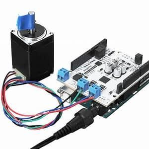
- Arduino Board (or any compatible microcontroller) — I’m using an Arduino Uno for this project.
- Power Supply — This could be a DC adapter or battery pack, depending on your power needs.
- Heat Sinks — JLCMC has great options for cooling components, especially if your project requires active heat management.
Just check the following heat sink accessory filter here and see if it suits you!
BR10260 Fan Parts (JLC) | JLCMC
- Brackets — Useful for securely mounting your components inside the enclosure.
Here below we have an L-shaped bracket, which is commonly used for mounting electronics in a 90-degree angle, perfect for holding components like the Arduino board or other sensors.
Aluminum Extruded Angle Bracket | JLCMC -- see second pic!
- Mounting Screws— To secure your electronics within the case.
Typically, M3 (3mm) screws are commonly used for mounting Arduino boards and other small electronics. If your components require larger screws, you can go up to M4 screws. The length of the screws will depend on the thickness of the enclosure and the height of the components you're mounting. For example, for mounting an Arduino Uno or similar boards:
Recommended Option:
M3 x 6mm or M3 x 8mm screws would be perfect for securing components inside the aluminum enclosure.
This kit contains a variety of M3 screws in different lengths and M6 screws, plus matching nuts. The fact that it includes M3 screws makes it a good option for your project, as you'll find both M3 x 6mm and M3 x 8mm screws (or similar sizes) in this kit.
You can take a look: M3-M6 Screw and Nut Kit (1750pcs) | JLCMC --see third pic!
- Standoffs
Standoffs are used to raise the components off the bottom of the enclosure to avoid short circuits and ensure stability. Here’s what you’ll need:
Material: Nylon or Metal (brass or aluminum) standoffs are commonly used. Nylon is great for lightweight projects and electrical insulation, while metal standoffs are more durable.
Thread Size: The standoffs should match the thread of the screws, so for M3 screws, you'll need M3 standoffs.
Height: For an Arduino Uno, 10mm or 12mm standoffs should work well to give enough clearance between the board and the bottom of the enclosure.
Recommended Option:
M3 x 10mm or M3 x 12mm nylon standoffs should be ideal for mounting your electronics safely. This standoff has a female thread on one end, which is ideal for mounting a component (like the Arduino board) to the base of your aluminum enclosure.
Hexagonal Shape: The hexagonal shape will make it easier to grip and tighten with a wrench or pliers when you're installing it, making the installation process easier.
Nylon Material: Nylon standoffs are great for insulating your components and keeping them from short-circuiting, which is important for protecting your electronics.
Single End Hex Standoff-Hex Stud | JLCMC--see forth pic!
- Connectors and Wires — For making all your necessary connections.
Tools:
- Screwdriver — To assemble everything securely.
- Dremel or Metal File — For customizing the enclosure (cutting out holes for ports or ventilation).
- Drill — To make precise holes for additional components (like cooling fans or extra ports).
- Ruler/Measuring Tape — To ensure accurate measurements for drilling and cutting.
- Pencil or Marker — For marking cut-out spots and measurement lines.
Planning and Design

Before starting to cut, drill, or mount anything, take a moment to design your system layout. Here’s how I planned mine:
1. Arduino Layout
When it comes to placing the Arduino board, consider the following:
- Position: I’ve chosen to place the Arduino board near the base of the enclosure. This is typically the most stable spot, and it leaves enough room for connections to the board, including the USB port and power connectors. You’ll need these ports to easily upload code or power the Arduino from an external source.
- Accessibility: The USB port should remain easily accessible, even after the enclosure is closed. This will allow easy programming and troubleshooting if needed.
- Mounting: You’ll want to mount the board securely, either using screws, adhesive, or brackets, so it doesn’t move within the case.
A representative image for this would show an Arduino mounted at the bottom center of an enclosure, with clear space left for USB and power ports.
Layout Visualization for the Custom Electronics Enclosure:
- Bottom Center of the Enclosure (Arduino Mounting)
- The Arduino should be mounted at the bottom center of the enclosure. This allows for easy access to the USB and power ports at the side of the enclosure. You’ll want to position the Arduino so that the USB port is aligned with one of the enclosure’s edges, allowing easy access when plugging in cables.
- Use mounting screws or double-sided tape to hold the Arduino in place. It can be securely fastened to the base of the enclosure without obstructing the USB port.
- Motor Driver and Power Supply
- Place the motor driver and power supply next to the Arduino, ensuring they don’t obstruct the USB and power ports. They could be mounted on the sides or upper portion of the enclosure, depending on the space.
- Make sure the motor driver is wired correctly to the Arduino and motor for movement control
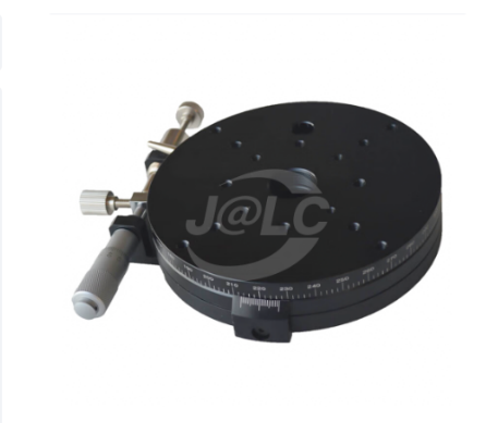
- Precision Rotary Manual Motion Platform (External Mounting)
- The Precision Rotary Manual Motion Platform will be mounted externally, attached to the front or side of the enclosure. It should be positioned so that it is easily accessible for manual adjustment. The platform should be aligned with the edge of the enclosure for a clean look.
- Wiring
- Wires and connectors should be neatly arranged to avoid interfering with the moving parts or access points. Use cable management techniques like zip ties or Velcro straps to keep everything tidy inside the enclosure.
2. Sensor/Module Placement
Now that the Arduino is situated, we need to plan where the sensors and modules will go. In this design:
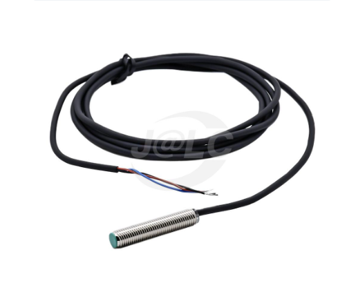
- Motion Sensor: I’ve chosen to mount the motion sensor on one side of the enclosure. This is often done because motion sensors have a wide field of view and need to be placed in a way that allows them to detect movement effectively without obstructions.
The BR9158 inductive proximity sensor from JLCMC could be a suitable choice for your project, but there are a few considerations to keep in mind before integrating it with an Arduino.
How to Connect It to Arduino
- Brown Wire → 12-24V Power Supply (+)
- Blue Wire → Ground (GND)
- Black Wire (Output) → Arduino Digital Pin (with a pull-up resistor to 5V)
- Servo Motor: The servo motor will be mounted on the opposite side. This helps with cable management, as the servo will have its own space, preventing tangled wires and helping the motor perform its function without interference.
PRO TIP: How to control a servo motor using an Arduino?
Use the Servo library in Arduino IDE. The Servo.h library comes pre-installed.
- Set up the servo object and attach it to a specific pin on your Arduino board.
- Specify commands for positioning or adjusting speed.
- You can also connect a potentiometer to control the servo motor angle.
- Connect the servo VCC pin to the Arduino 5V output pin and the servo GND pin to the Arduino ground pin
3. Ports and Ventilation
For the final part of the design, you’ll need to ensure that your system doesn’t overheat and has proper connectivity:
- USB and Power Ports: Position the USB and power ports in a location that's easy to access when the enclosure is closed. These ports allow for easy power connections or programming updates.
- Ventilation: To avoid overheating, it’s essential to include ventilation holes. These can be small, circular holes or slotted cutouts along the sides or top of the enclosure. Proper ventilation will keep components from getting too hot, which is especially important for devices like the Arduino and servo motors that can generate heat during operation.
A representative image for this part would show an enclosure with visible port cutouts and ventilation holes on one side, ensuring good airflow.
4. Cable Management
While this wasn't mentioned initially, it's always good to consider cable management during your design phase:
- Plan where cables will run and how they will be secured.
- You can use cable ties, cable channels, or small clips to keep everything in place.
- Try to avoid crossing power cables with signal wires to minimize interference.
Take your time with this step to ensure everything fits properly. You don’t want to have to redo any cuts later!
Preparing the Enclosure

Now that your design is ready, it’s time to prep the Split Aluminum Enclosure.
- Cutting Out Ports: Using a Dremel or metal file, carefully cut out the holes for any USB ports, power jacks, or serial connections that you’ll need access to. Ensure the cutouts are clean and precise so that your connectors fit snugly.
- Ventilation: If your project generates heat, like an Arduino-based motor controller, you’ll want to add some ventilation. Use your drill to add small holes or slits along the sides or top to allow for airflow.
- Marking and Drilling: Use a ruler and pencil to measure and mark where you’ll drill holes for mounting screws, standoffs, or any additional components like fans or LED indicators.
Mounting the Electronics
Once your enclosure is ready, it’s time to mount your Arduino board and any other components.
- Install the Arduino: Use standoffs and screws to securely mount your Arduino board to the bottom of the enclosure. Make sure the USB port is accessible from the exterior so you can easily program the board later.
- Place Additional Components: Mount any sensors or motors using the appropriate brackets and screws. Be mindful of cable management, ensuring that no wires get pinched or tangled.
- Heat Management: If you're using heat-sensitive components, this is the time to add heat sinks. Attach them to the Arduino or other components that may overheat during operation.
Wiring and Powering Your Project
With your electronics securely mounted, it’s time to wire up everything. Here’s how I did it:
- Power Supply: Connect the DC power supply to your Arduino or electronics. If you’re using a battery pack, ensure it’s properly wired to the Arduino’s power input.
- Connect Sensors/Modules: Run the necessary wires to each sensor and connect them to the appropriate pins on the Arduino board. Make sure to organize the wiring to keep everything neat and avoid any shorts.
- Test: Before closing up the enclosure, it’s a good idea to test your system. Power it up and check that all components are working as expected.
Final Assembly
Once everything is in place and wired, it’s time to finalize your build:
- Close the Enclosure: Secure the top part of the enclosure using the provided screws. Make sure everything fits tightly, but don’t overtighten.
- Test Everything: Power up your system one last time to make sure everything is working as it should.
Code and Software
Now comes the fun part — programming! I’ve written some simple code for an Arduino-based sensor that I’ll use with this enclosure.
To integrate all the components for your project, including the Proximity Sensor, Arduino, and possibly additional components like an LED or motors, here’s an outline of the code needed to make everything work together.
Full Code Example:
cpp
CopyEdit
// Pin Definitions
int proximityPin = 2; // Pin for Proximity Sensor (Input)
int ledPin = 13; // Pin for LED (Output)
int sensorValue = 0; // Variable to hold sensor data
void setup() {
pinMode(proximityPin, INPUT); // Set proximity sensor pin as input
pinMode(ledPin, OUTPUT); // Set LED pin as output
Serial.begin(9600); // Start serial communication
}
void loop() {
sensorValue = digitalRead(proximityPin); // Read the value from the proximity sensor
if (sensorValue == HIGH) { // Object is detected (sensor is triggered)
digitalWrite(ledPin, HIGH); // Turn LED on
Serial.println("Object Detected!"); // Print to Serial Monitor
} else {// No object detected
digitalWrite(ledPin, LOW); // Turn LED off
Serial.println("No Object Detected."); // Print to Serial Monitor
}
delay(100);// Delay for stability
}
How the Code Works:
- Pin Setup: The proximity sensor is connected to pin 2, and the LED is connected to pin 13.
- Input from Proximity Sensor: The sensor sends a HIGH or LOW signal to the Arduino based on whether it detects an object.
- LED Behavior: If the sensor detects an object (sensor value HIGH), the LED turns on. If no object is detected (sensor value LOW), the LED turns off.
- Serial Monitor: The status of the sensor is printed to the Serial Monitor for debugging purposes.
Conclusion
To Expand the Project:
- You could add more sensors (for example, using more pins for additional proximity sensors).
- Integrate motors or servos to trigger actions when objects are detected.
- Use PWM pins for controlling motors or LED brightness based on the sensor's distance output.
And there you have it: a DIY custom housing for your electronics project using the JLCMC Split Aluminum Enclosure. Whether you’re making a sensor, a motor controller, or any other device, this enclosure provides the protection and versatility you need.
What’s great about this project is that it’s just the beginning. You can customize the enclosure further with LED indicators, cooling fans, and more sensors to fit your needs.
Happy building!