JOYSTICK TESTING WITH DESHBOT
by devkrishnavhora in Circuits > Arduino
6 Views, 0 Favorites, 0 Comments
JOYSTICK TESTING WITH DESHBOT
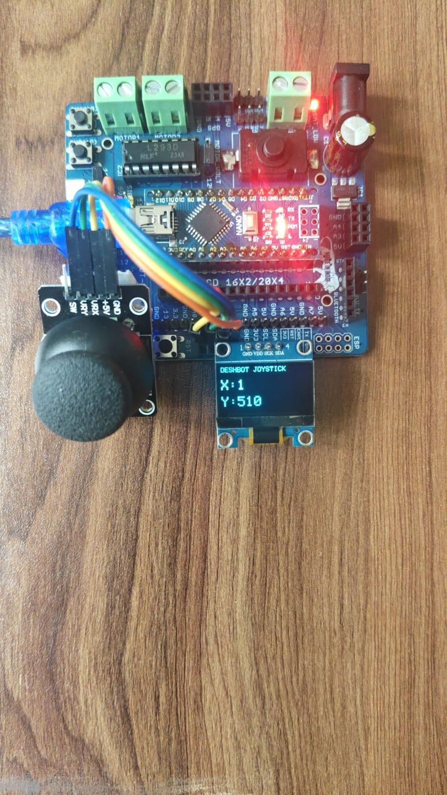
This project demonstrates how to connect and use a joystick module with an Arduino Nano and the DESHBOT Shield. The joystick is used as an input device, while an OLED display shows the joystick movement and values in real time.
The project is simple, compact, and useful for learning how analog and digital input
Supplies
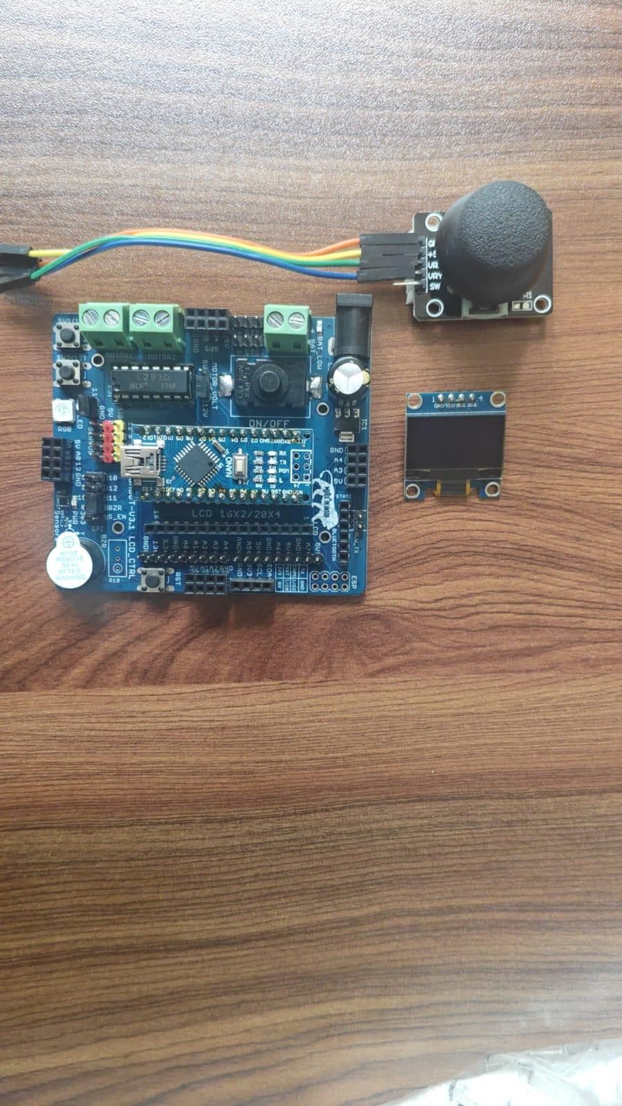
Arduino Nano
DESHBOT Shield
Joystick Module
I2C OLED Display
Connecting wires
USB cable
Connections
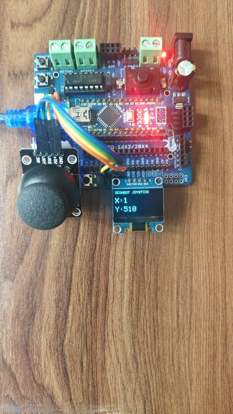
Joystick Connection
The joystick is connected to the DESHBOT Shield as follows:
- VRX → Pin A1
- VRY → Pin A2
- VCC → 5V
- GND → GND
OLED Display Connection
The I2C OLED display is connected as follows:
- VCC → 5V
- GND → GND
- SDA → A4
- SCL → A5
The Arduino Nano is mounted directly onto the DESHBOT Shield, making the component connections easier and more organized.
Coding and Uploading
- Open the Arduino IDE on your computer.
- Connect the Arduino Nano with the DESHBOT Shield using a USB cable.
- Select Arduino Nano from Tools → Board.
- Select the correct Processor and COM Port.
- Install the required libraries:
- Adafruit GFX Library
- Adafruit SSD1306 Library
- Copy and paste the joystick and OLED program into the Arduino IDE.
- Check that the pin definitions match the DESHBOT Shield connections:
- VRX → D13
- VRY → A0
- OLED SDA → A4
- OLED SCL → A5
- Click the Verify button to compile the code.
- Click Upload to upload the program to the Arduino Nano.
- After uploading, move the joystick and observe the joystick values on the OLED display.
Downloads
Working Principle
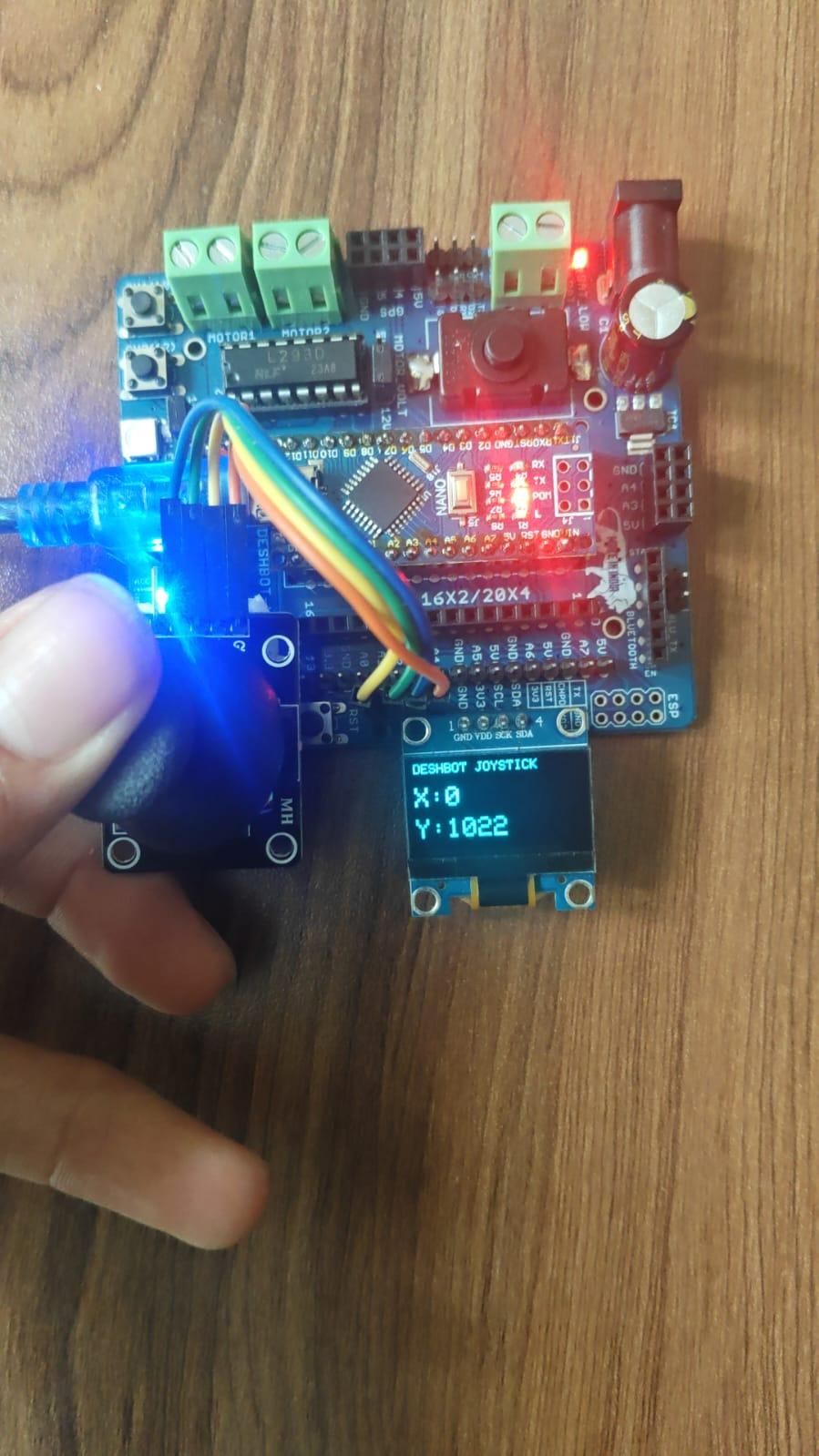
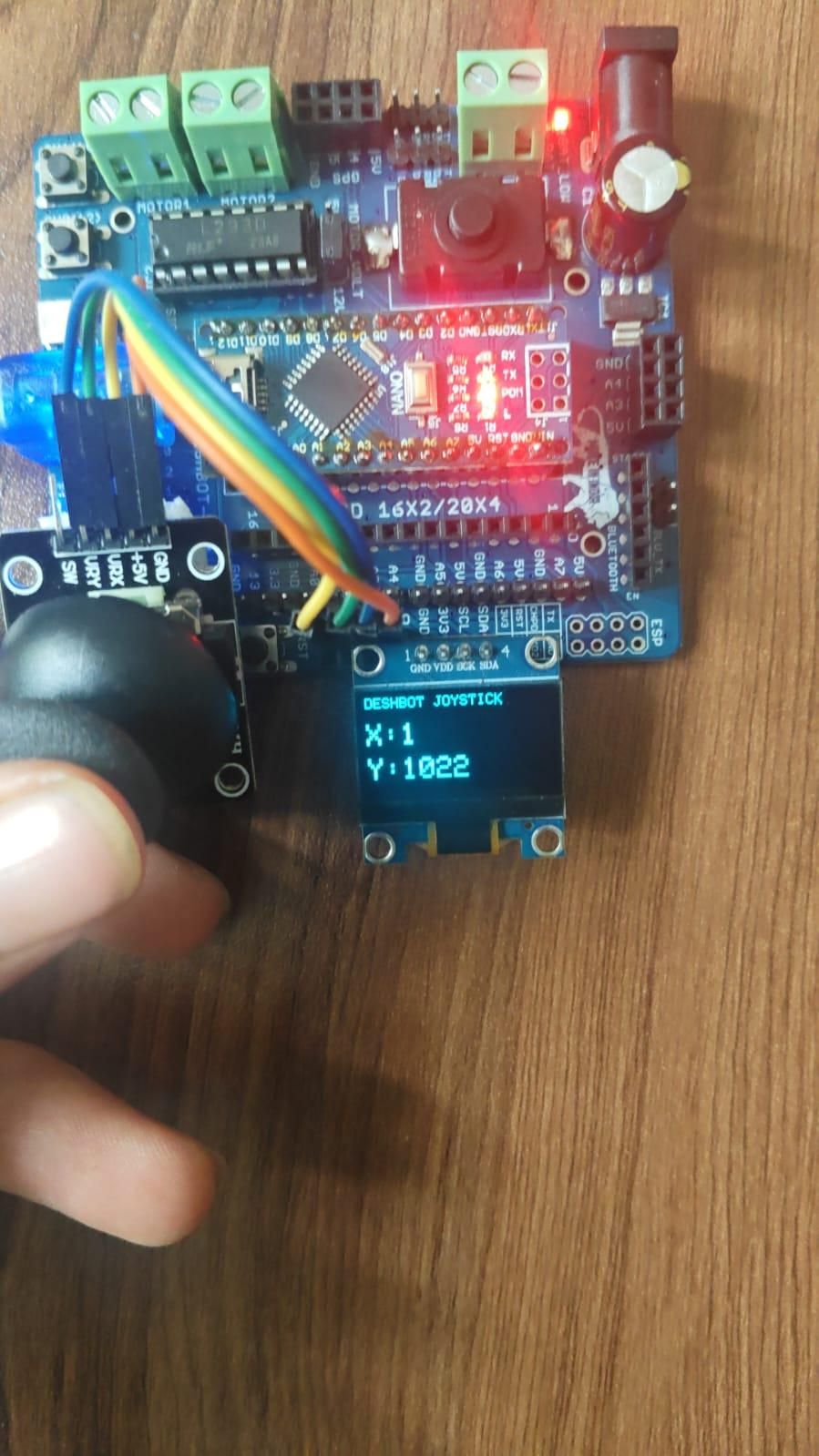
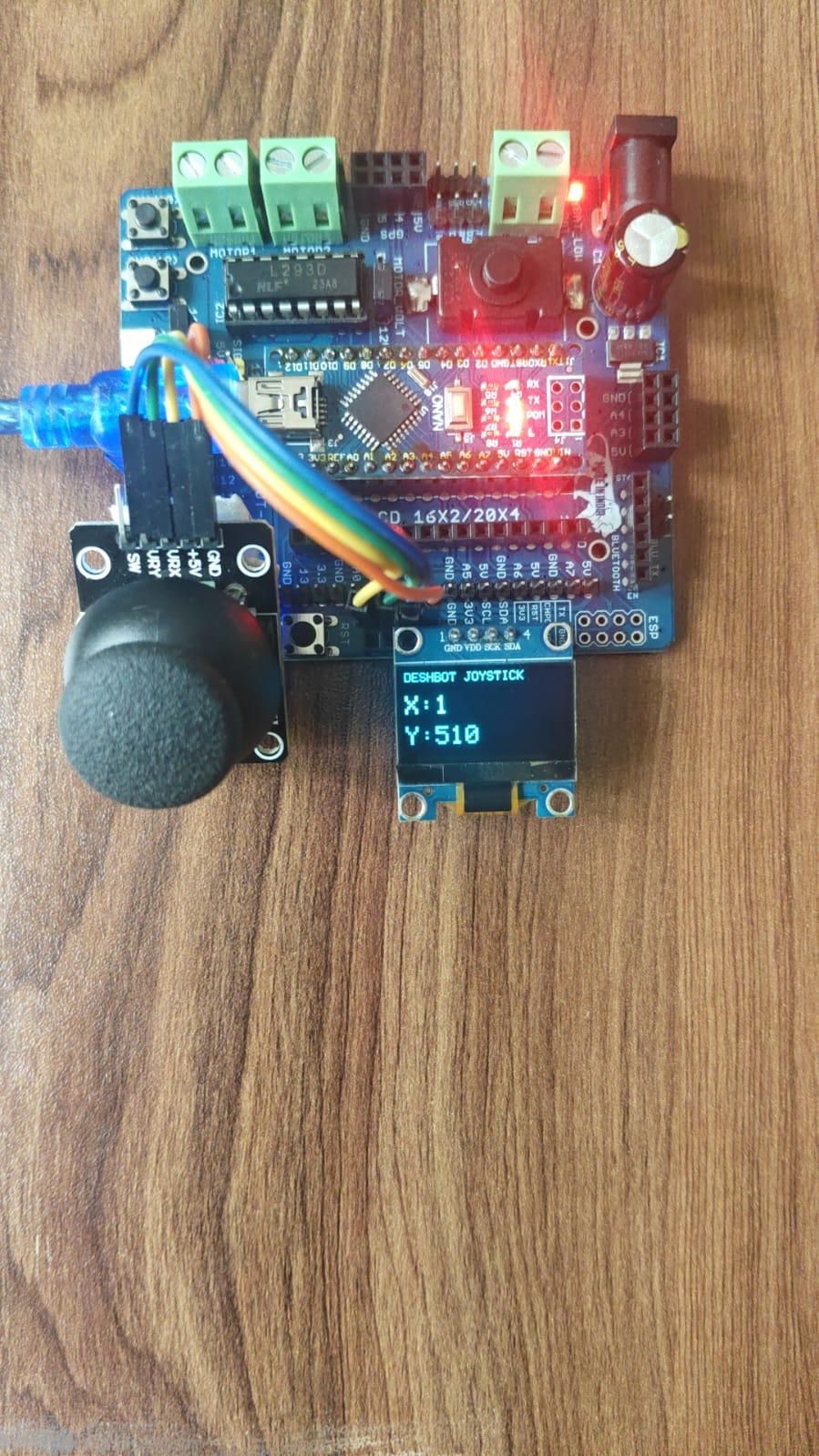
The joystick has two movement directions: X-axis and Y-axis. When the joystick is moved, the Arduino Nano reads the signals from the joystick pins.
The VRY signal is read through analog pin A0, and its value changes according to the joystick position. The joystick data is then processed by the Arduino Nano.
The OLED display shows the joystick information in real time. This allows the user to visually monitor the joystick movement and sensor values.
How It Works
- Connect the Arduino Nano to the DESHBOT Shield.
- Connect the joystick module to the required shield pins.
- Connect the OLED display using the I2C pins.
- Upload the Arduino program.
- Power the Arduino Nano.
- Move the joystick in different directions.
- The Arduino reads the joystick input.
- The OLED display updates and shows the joystick values.
Features
- Real-time joystick input reading
- OLED display output
- Compact design using the DESHBOT Shield
- Easy Arduino Nano programming
- Useful for robot and game controller projects
- Simple connection and operation
Conclusion
The Joystick Control System using Arduino Nano and DESHBOT Shield is a simple project for understanding joystick input and OLED display interfacing. The DESHBOT Shield makes it easier to connect the Arduino Nano and external modules. The project can also be expanded in the future to control motors, robots, menus, or other electronic devices.