KIRBY Compact Soldering Fume Extractor (Improved)
by SoorBuilds in Circuits > Soldering
136 Views, 4 Favorites, 0 Comments
KIRBY Compact Soldering Fume Extractor (Improved)
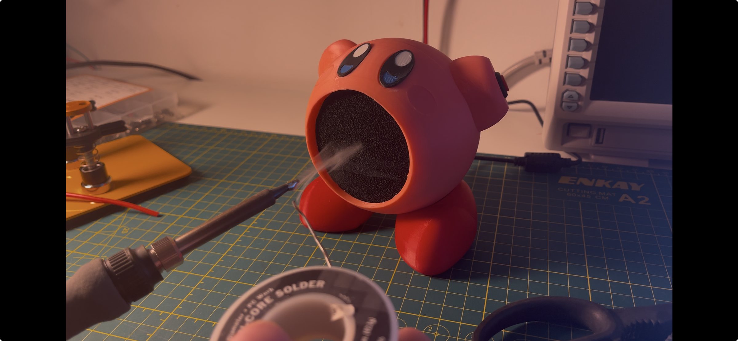
I modified the design made by Youtuber Chris Borge: I upscaled it to fit a CRAZY POWERFUL industrial server fan, added a button for convenience, and a connector for easy plug in/out.
Supplies
SilverStone FHS60X (small but very mighty fan)
Barrel jack power connector (you don't need it... but you want it :)
12v 2A power brick (you can probably find one around your house, make sure on the back it says 12v 2A)
Latching button (you don't need it... but you want it :)
M3 Nuts and bolts (very useful for 3d printed assemblies, I recommend you buy these even if you aren't making this)
Activated Carbon filter (I looked everywhere for the cheapest and this was it, luckily since Kirby is compact, each of the 5 square filters is able to make 4 Kirby circles, not bad...
Buy the Parts / Remodel Around Your Parts
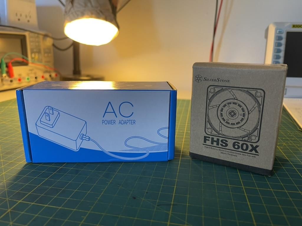
Buy the parts or if you would like to modify my design to fit your existing parts, do that!
3d Print Kirby

The STEP files are down below, if you would like each of the individual STL files, you can find them at (PRINTABLES LINK)
P.S. use tree supports because they're cool
Remove the Support Material

If you were using tree supports this should be easy... and oddly therapeutic
Heat Set Insert

Insert the heat set inserts, don't make the same mistake as me and turn your soldering iron to as high a temp as it can go! otherwise, you will need to apply too much pressure and the iron tip will get wedged into the heat set inserts, not ideal.
Add the Button


Just shove the button into the left arm! I am proud of this design because it should fit perfectly and require no complex assembly.
Add the Power Connector


Here, I gave up trying to get the tolerance to be press fit (like the button above) so I gave up and decided to treat the metal connector as a heat set insert :) My advice is to crank up your soldering iron to max heat and press down with the tip
Connect Up the Wires
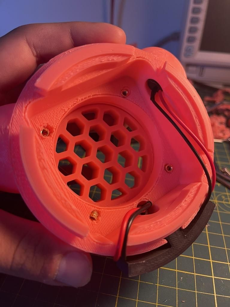

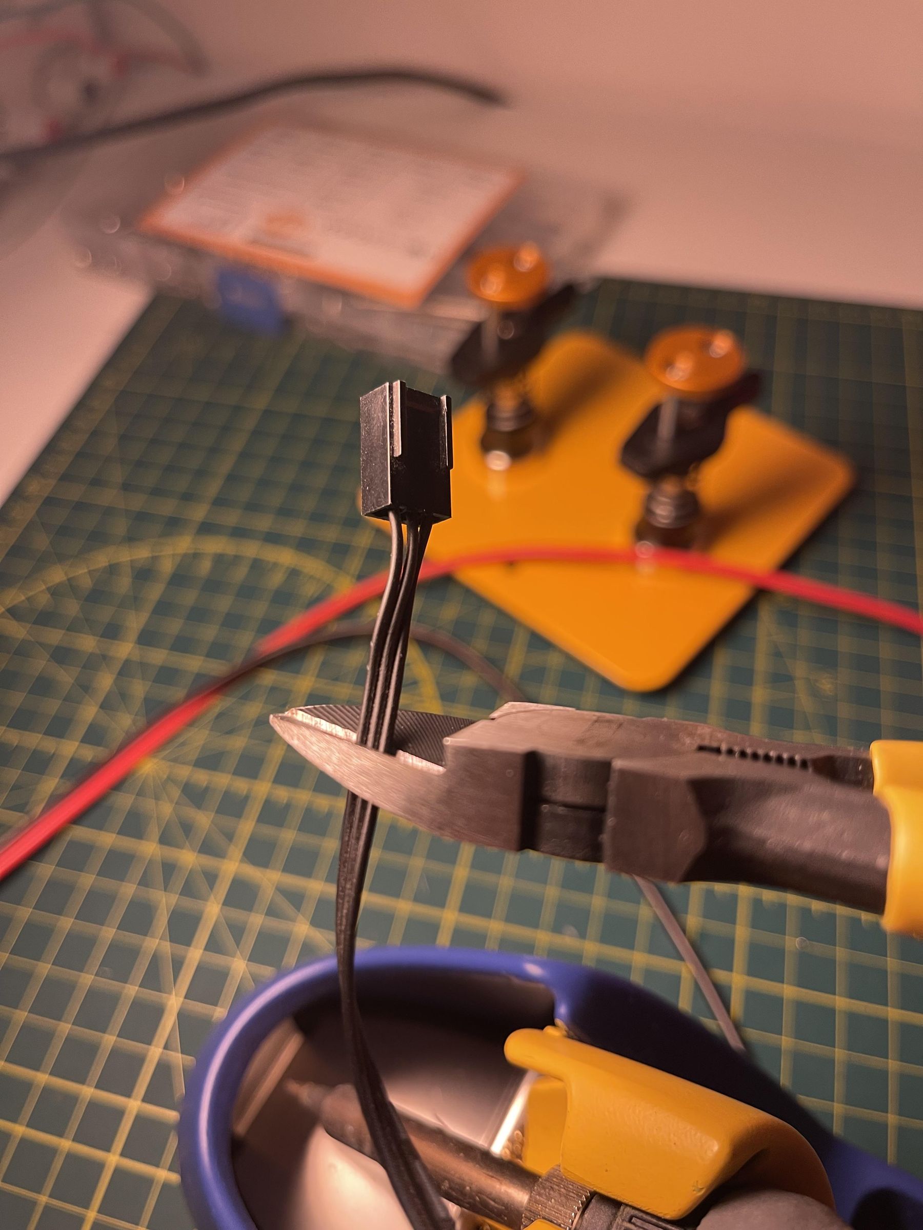

If you're making this for soldering, you know what to do here:
- Cut off the connector to your fan. Since all the wires are black, make sure to make a mental note which one is + and - , On my fan, the connector showed an arrow on it and GPT told me that one was - , your fan might be different so make sure to test continuity with a multimeter before powering up!
- Connect everything up with alligator clips to make sure your circuit works properly
- Solder the wires together, don't forget heat shrink tubing like I somehow kept forgetting!
- Screw in the fan
- Tuck in the wires wherever there's room
Finish Assembly
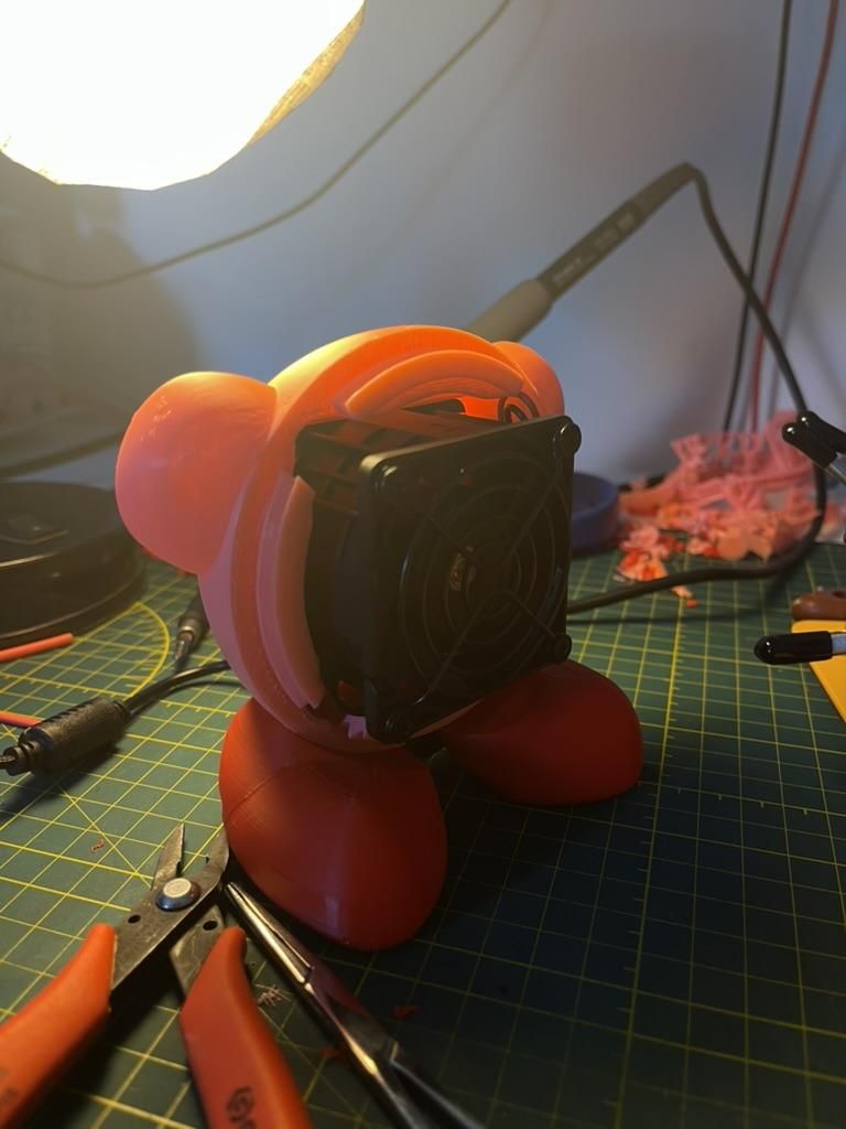

Assemble! if something doesn't seem to fit, you probably missed some rogue support material, make sure to remove it, I recommend you to go looking around for some tweezers or long pliers to get the job done.
Add the Filters

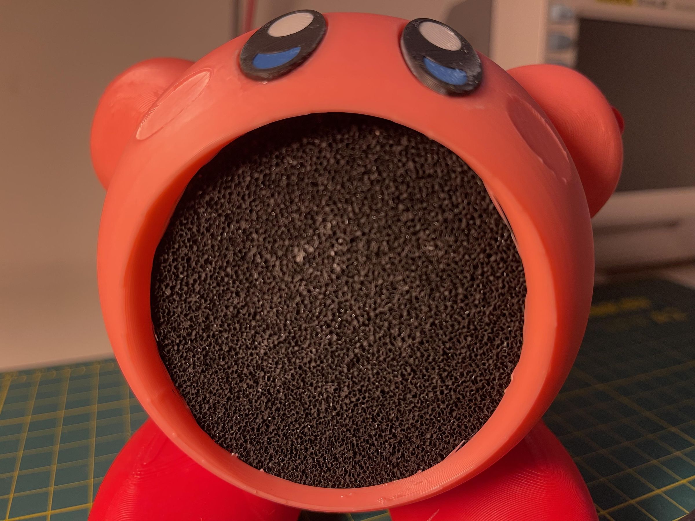
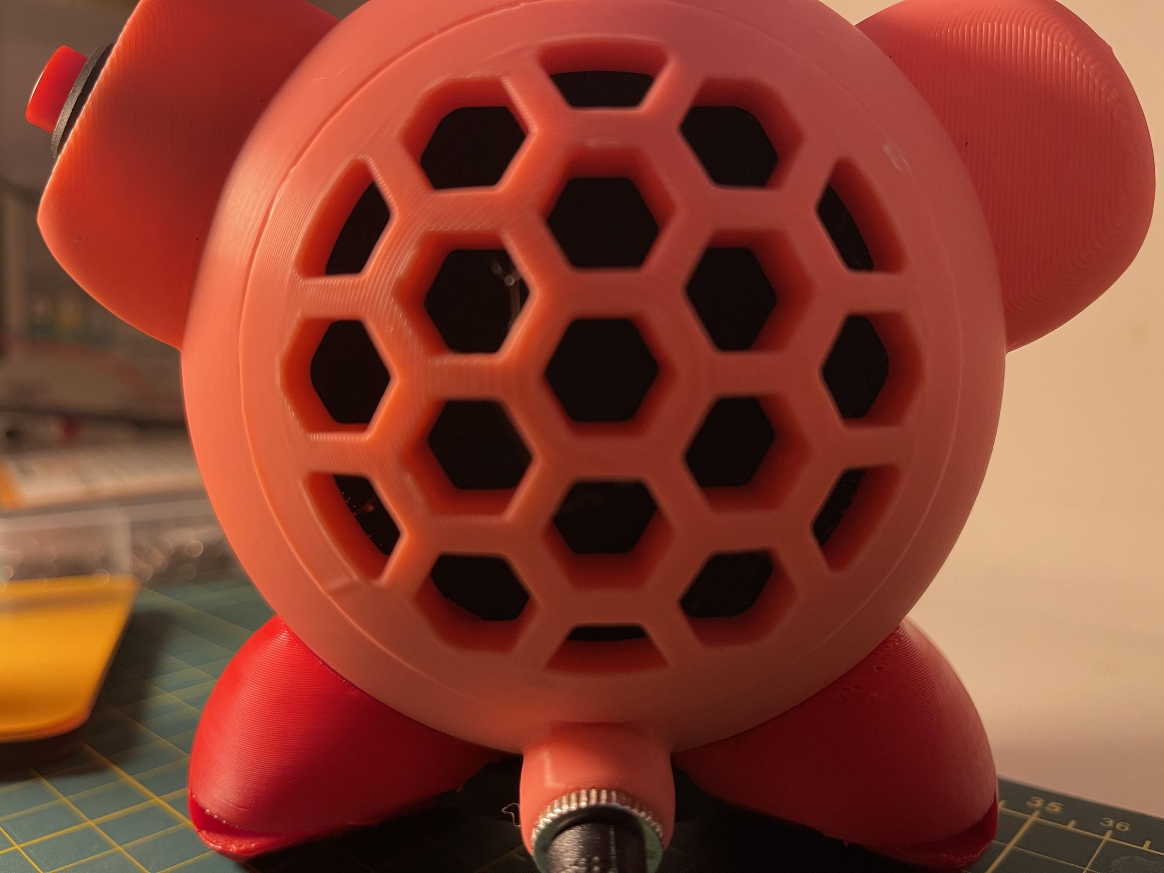
Cut out your carbon filter to be slightly bigger than the intake and exhaust holes. You don't have to add a filter to the exhaust hole, but it should hopefully remove any particles that make it through stage 1.
Kirby!
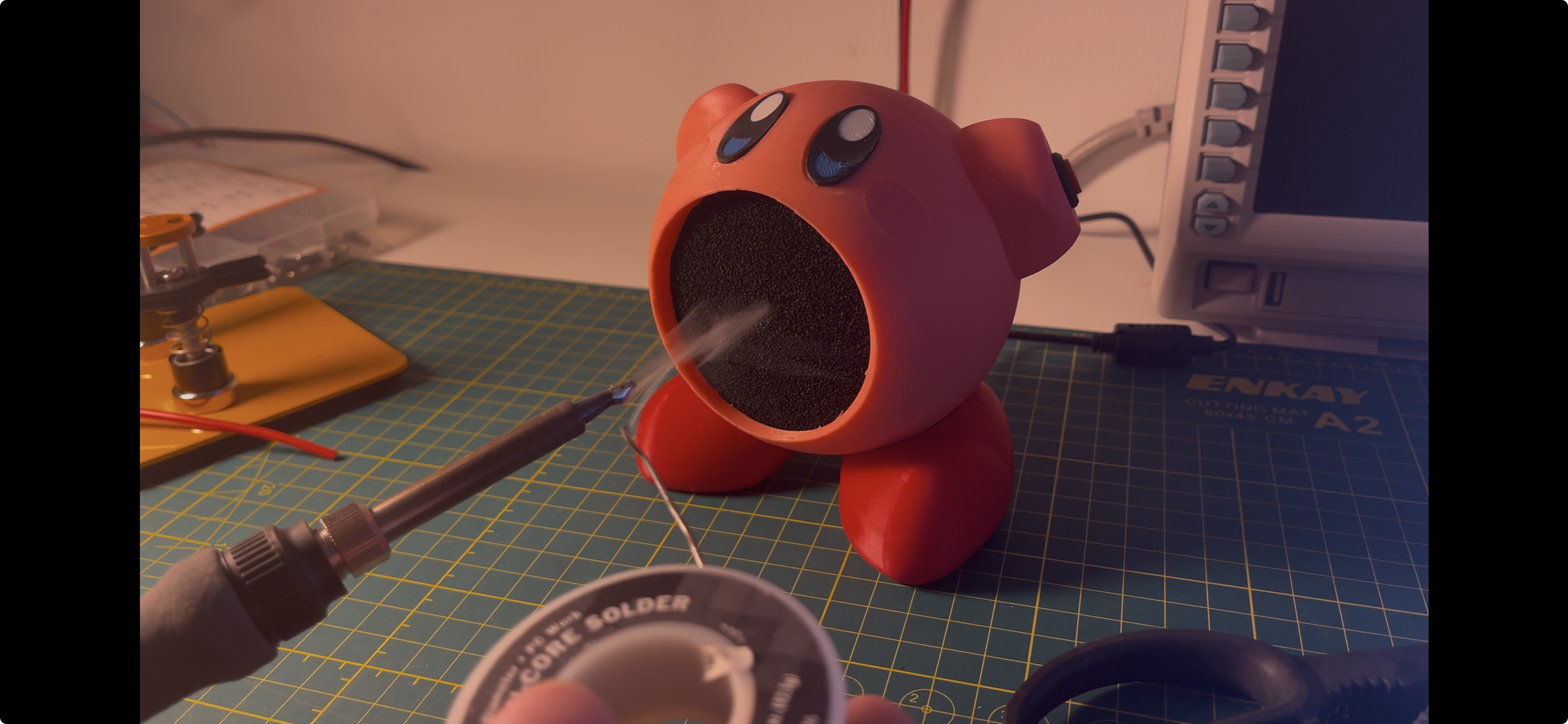
Happy soldering! Remember to replace the filters when they start looking greyish.