Spatial Synthesizer Kravox! Wireless, Motion- & Touch-Sensing
by timkrahmer in Circuits > Arduino
10610 Views, 83 Favorites, 0 Comments
Spatial Synthesizer Kravox! Wireless, Motion- & Touch-Sensing
A New Kind of Instrument
I invented Kravox during a research project at Lund University (Sweden) with the aim to give digital musical instrument controllers the feeling of conventional, mechanical instruments. Now I want to make Kravox accessible as a musical experimentation platform for everyone, so I created this detailed Instructable to enable as many people as possible to use this exciting new instrument!
How to Play Kravox
Playing Kravox is as quite straightforward. Just imagine you are playing around with an ordinary object like a broom and the way you touch and move it through space controls how sound is generated. See and hear how to play Kravox in this video.
What Is Kravox?


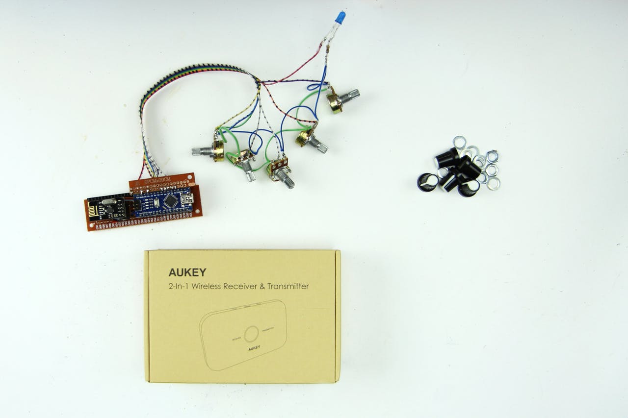
Kravox is a cross-platform compatible, open source digital musical instrument that consists of three components – controller/s, receiver and software.
Controller/s
Up to three wireless controller devices can be connected. Each controller processes orientation- and acceleration data from a digital MPU-6050 gyroscope and touch data from two MPR121 touch sensor boards connected to an Arduino Nano. The controller/s send/s the data to a receiver device via nRF24L01 radio transceiver/s. If more than one controller shall be used, the second and third controller need to get individual addresses assigned. For more information about assigning the address see the info in the DECLARATIONS / NRF24L01 section of the controller code.
Receiver
The receiver passes the data received from the controller/s on via USB to a connected computer, together with data collected from several potentiometers. The provided receiver device code allows communication with up to three controllers, but will also work with only one or two without adjustments.
Software
The data from the receiver is processed in a programme written in Pure Data Vanilla that outputs sound.
What We Will Build (incl. Video Tutorial!)
![Wireless Pure Data Arduino Synthesizer – How to build your own Kravox [Tutorial]](/proxy/?url=https://content.instructables.com/FVP/3Y81/JM0V4YVL/FVP3Y81JM0V4YVL.jpg&filename=Wireless Pure Data Arduino Synthesizer – How to build your own Kravox [Tutorial])

The beauty of Kravox is that it's shape, how it sounds and how it's played can be adjusted. This gave me the opportunity to design an easy-to-replicate Kravox version for this tutorial. Both the video above and this Instructable will show you all necessary steps of how to build fully functional controllers and a receiver from easily available electric components and cardboard.
(In case you are curious: On my youtube-channel you can also find a timelapse of how I made the larger version of Kravox)
Components

You will need the following components to build a Kravox controller + receiver station:
- {1x} 50*24 hole (minimum size) Perfboard,
- {5x} 40-Pin female headers,
- {5x} 40-Pin male headers,
- {5x} 10 kilo-Ohm potentiometers and Knobs for them,
- {3x} Blue 5mm standard LEDs,
- {3x} 150 Ohm resistors,
- {2x} 10 micro-farad capacitors,
- {2x} 100 nano-farad capacitors,
- {2x} NRF24L01 radio transceivers,
- {2x} Arduino nanos,
- {3x} 220 Ohm resistors,
- {2x} MPR121 touch sensor boards,
- {1x} GY-521 MPU 6050 digital gyroscope,
- {2x} USB-A to USB-C cables,
- {1x} 4 meters (minimum) of 1 cm wide copper tape,
- {1x} powerbank,
- {1x} 7 meters (minimum) wire in many colors and optionally
- {1x} 0, 2 meters of ø=3mm shrinktube.
Tools
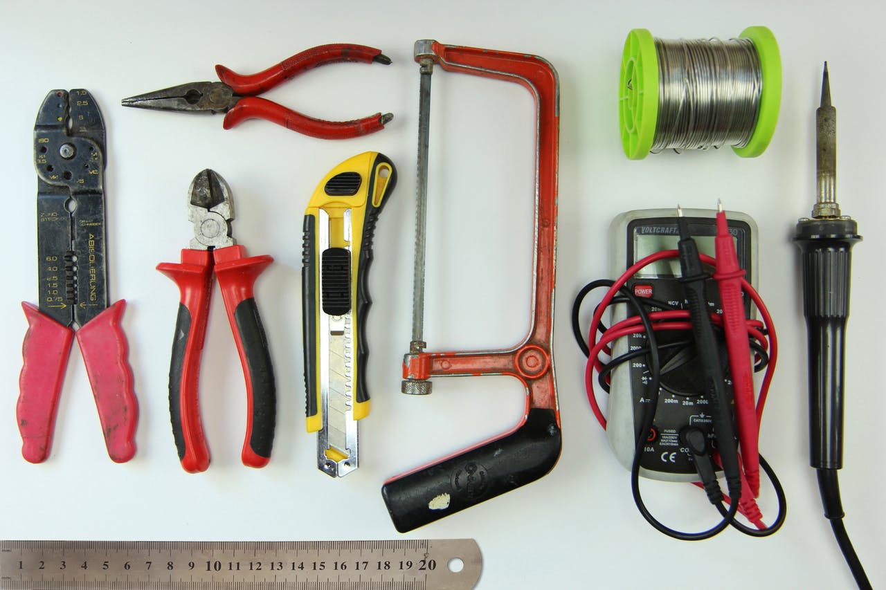
You need the tools in the picture to assemble the components:
- Wire Stripper
- Pliers
- Utlity knife
- Hacksaw
- Ruler
- Multimeter
- Soldering Iron + Solder
Cardboard-enclosure Making Material and Tools
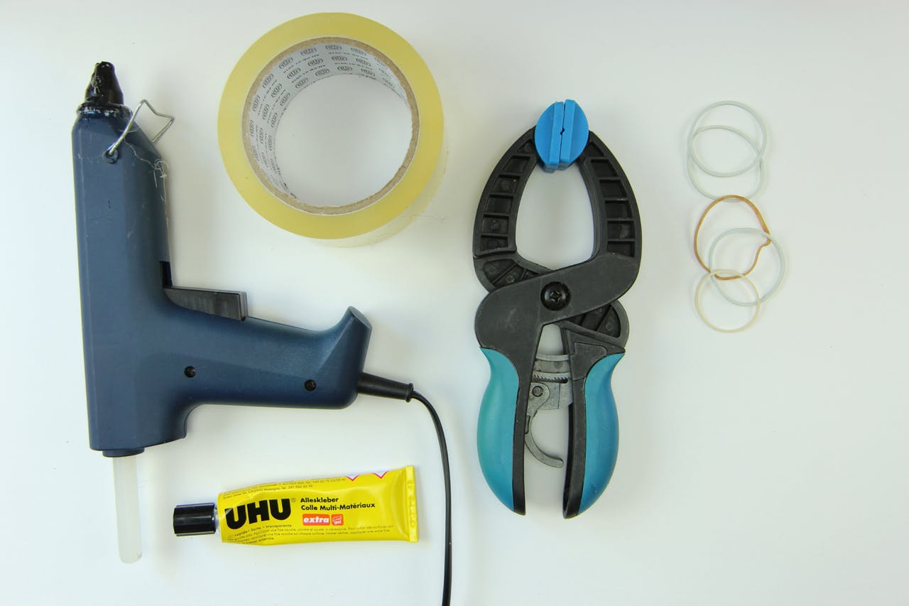
Later in the making process you also need some empty cardboard boxes or similar and glue, a glue gun, adhesive tape, one or more clamps and rubber bands to make the enclosures
Making the Controller Board


Next I will explain how to make the controller electronics step by step from the parts mentioned above
If in doubt, where to solder in a cable, you can always come back to the circuit diagram and check, if the components will be connected right, once you attach the arduino and sensor-boards to the circuit board we are creating
Making the Controller Board - Making the Circuit Board


The first step is to cut the perfboard and female pin-headers to size
and assemble them together with a small and a big capacitor that help increasing the reliability of the radio-transceiver
- Cut the perfboard with a utility knife
- Cut the female pin headers with ahacksaw (I put them on a book to level them from the tabletop)
- Solder in the parts. You can already connect each pin-pair of the two
long female headers that sit next to each other. For the remaining headers it is enough to simply attach them with a little solder – preferably the pins that will have according to the circuit diagram no connection later anyway. When soldering in the capacitors, pay attention to the polarity of the electrolytic 10-micro-farad capacitor (the bigger one of the two). One side will have a stripe and usually also a shorter leg. That side needs to be connected to ground. The smaller 100nano-farad-capacitor is not polarized and can be soldered in either way
Making the Controller Board - LEDs


The second step is to solder in the two LEDs with their current limiting resistors
Pay attention to the polarity of theLED: One side of it is flattened and
will usually also have a shorter leg. That side needs to be connected to ground in step 2.3. The other side we will now connect with a cyan coloured cable to the jack where Arduino pin D3 will later sit when plugged in
Making the Controller Board – Power Supply Cables


Next we add all the red and blue power supply cables. Red is for 3.3 Volts and blue for ground (GND)
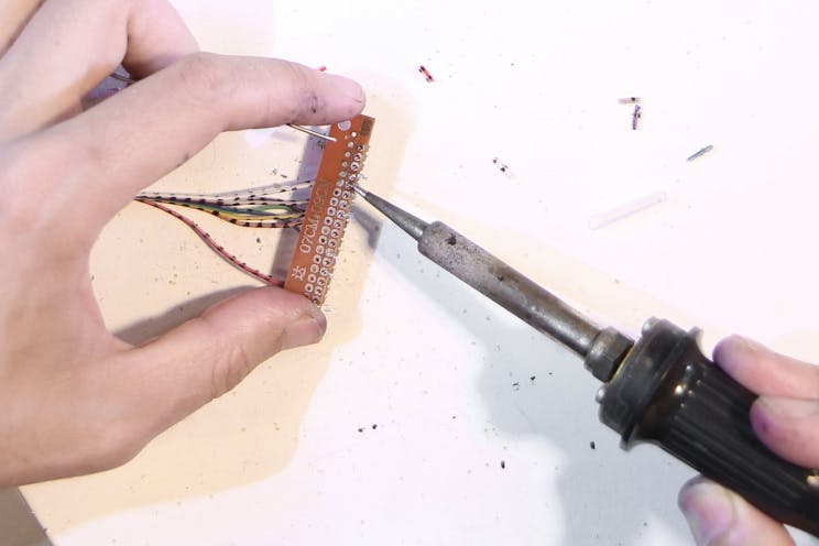
Making the Controller Board – I2C-Connections


In the fourth step it is already getting a little crowded on the board.
The three sensor boards communicate via the I2C-protocol (inter-integrated circuit). That means that they can all be connected to the same two Arduino pins, so we solder in yellow and green cables between them and Arduino-pins A4 and A5. We also add a white cable for the Gyroscope’s interrupt pin connection
Making the Controller Board – SPI Connections


The radio transceiver communicates via the SPI-protocol instead (serial
peripheral interface) that requires more connections than I2C, so we add black, grey, brown, purple and orange cables
Making the Controller Board – Preparing Components


Now it’s time to prepare the components
Apart from soldering on the male pin headers if they are not
pre-soldered, pay special attention to the touch sensor boards! The cheap models from china have their address pin hardwired to ground without a pulldown-resistor in between, so you need to physically cut this connection on the bottom of the board with a utility knife. Cut between the two solder pads next to where ADD is written. I recommend to use a multimeter to check that no connection is left between the pads afterwards
Making the Controller Board – Attaching Components


When all components have their pin headers soldered on and the touch
sensor boards are prepared, you can plug the Arduino Nano, the gyroscope, the two touch sensor boards and the radio transceiver into the controller board:
Making the Controller Board – Uploading Code
After double-checking, if everything is wired correctly, the next step is to upload the provided Kravox-Controller code to the Arduino nano, but before you can do so, you will need to install libraries for the gyroscope, the touch sensor boards and the radio transceiver. If you are new to Arduino-libraries, find out how to install them here.
- The MPU6050 gyroscope requires the libraries "I2Cdev.h" and "MPU6050_6Axis_MotionApps20.h" by Jeff Rowberg that can be downloaded here.
- The MPR121 touch sensor boards need the "MPR121.h" library by Bare Conductive that can be found here. There exist at least two versions of the library. Make sure to install the version developed by Bare Conductive and not the one developed by Adafruit.
- The NRF24L01 radio transceiver board requires the libraries "nRF24L01.h" and "RF24.h" by TMRh20 that can be downloaded here. Please note: There also exist at least two versions of those libraries with identical names. Make sure to install those developed by TMRh20 and not the ones by maniacbug.
- As soon as the libraries are installed you can upload the Kravox-Controller code
Optional: Test If the Controller Works


If you would already like to check, if ithe controller is working, you can let it output data from the touch sensors and the gyroscope via the Serial Monitor. For that you need to uncomment the last section of the receiver code before uploading: By deleting the comment marks in the beginning ( /* ) and in the end ( */ ) of it (See pictures)
After uploading the code with that variation, open the Serial Monitor, and set it to a baudrate (data transfer speed) of 115200. Now you should be able to see data from the sensors that changes when you move the controller board and touch the pins of the MPR121-boards that are labeled from 0 to 11.
If nothing works or you get only zeros, check your wiring carefully and compare it to the circuit diagram above. If you get a funny output from the Serial Monitor, check if you have set it to the correct baudrate.
Making the Controller Board – Powerbank

Connect your controller board to the powerbank you want to use with it.
If the board (or more precisely the powerbank) does not turn off automatically after some time, your controller board is finished and you can proceed to the receiver-board! Otherwise perform the next step Increasing Power-consumption
Making the Controller Board – Increasing Power-consumption...


In principle the controller-board is done, but some powerbanks will automatically turn off after a few seconds when connected to the controller-board as it is right now because it consumes so little energy As a dirty fix we can just add three 220 Ohm resistors in parallel between the 5V and GND pins of the Arduino. Those resistors will dissipate additional energy and transform them into heat, so the controller consumes enough for the power bank to stay on. Don’t worry: even with a small power bank it will still work for days non-stop without recharging Remove the Arduino Nano and solder in the resistors like in the picture
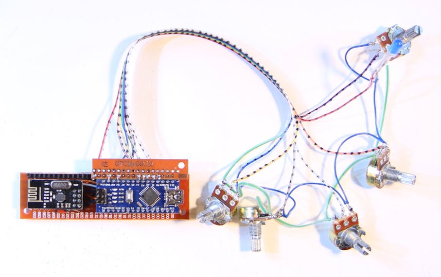
The Finished Controller Board


After re-attaching the components the (definitely) finished controller board looks like that
Making the Receiver Board


In this part of the tutorial I will show you how to make the receiver board. The process is pretty similar to making the controller board
If you want to check, where a certain cable should be connected, you can refer to this circuit diagram
Making the Receiver Board – Making the Circuit Board


The first step is again to cut the perfboard and female pin-headers to size and assemble them together with a small and a big capacitor that help increasing the reliability of the radio-transceiver. The lowest female pin header is intentionally left longer than necessary, so you can potentially use it for other projects like an Arduino granular Synth later. You can compare this step with the first making-the-controller-board step for more info
Making the Receiver Board – Power Supply Cables


Next we add all the red and blue power supply cables. Red is for 3.3 Volts and blue for ground (GND)
Making the Receiver Board – SPI Communication


Soldering in the Cables for SPI communication:
Making the Receiver Board – Attaching the Components


The receiver board is finished now, but before we can upload the Kravox-Receiver code to the Arduino Nano, we first need to make an interface for the receiver
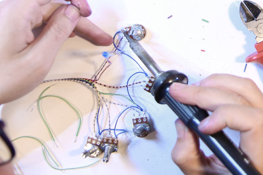
Making the Receiver Interface


In this part of the tutorial I show you how to make an interface with 4 potentiometers and an LED for the receiver. The interface is wired as in the first picture and will be plugged into the receiver board as can be seen in the second picture.
Making the Receiver Interface – Connecting the Potentiometers
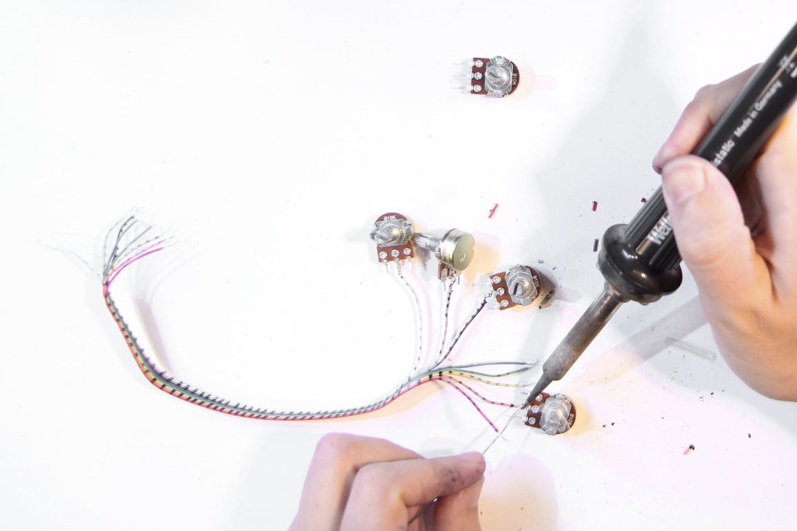
Proceed like this: First take a cable strand of 8 cables and solder 5 of them to the middle pins of the potentiometers. Preferably use the same colors as in the diagram to not get confused
Making the Receiver Interface – Perfboard

Next, cut a 2 * 17 hole wide perfboard and a 17 pin male pin header to size
Making the Receiver Interface – Making the Plug
Attach the cables and the pin header to the board. Pay attention to the circuit diagram above to make sure, that you connect the cables in the right places
Making the Receiver Interface – LED
Now connect one side of all the potentiometers with blue ground-connection-cables (and maybe use slightly longer cables than I did). Also add the blue LED with it's current limiting 150 Ohm resistor. Again pay attention to the LED's polarity (compare to the second step of making the controller board)
Making the Receiver Interface – +5V-connections

Next connect the other side of all potentiometers with green 5V-connection-cables (and maybe use slightly longer cables than I did)
The Finished Receiver Interface
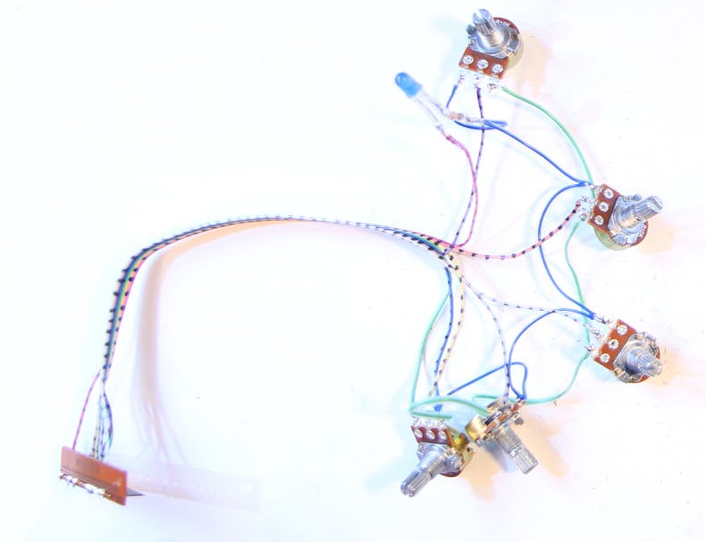
The finished interface should look similar to this (picture 1) and can be plugged into the receiver board like that (picture 2)
Uploading the Receiver Code


Now you can also upload the Kravox Receiver code to the receiver's Arduino Nano.
If you want to see if it is working and receiving data from the controller, you can again make a slight adjustment to the code before uploading. By default the Receiver will output it's data in a format that can be interpreted by pure data, but will not show useful information on the Serial Monitor. However you can change this behaviour in the code by commenting (adding // in front of) the line that says:
#define WRITE_AS_BYTES
and uncommenting (removing // in front of) the line that says:
// #define PRINT_VIA_SERIAL_MONITOR
You can see a Kravox data logging demonstration (including a description how to alter the code) in the video above
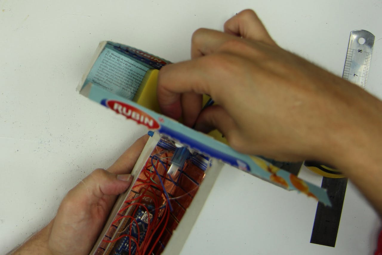
Making the Controller Interface + Enclosure

Like the receiver, the controller also gets an interface – a touch interface that we will make from copper tape
Making the Controller Interface + Enclosure – Components

As we directly want to attach the touch interface to the controller's enclosure, you should already have the (non-conductive) material at hand that you want to make the enclosure from. I used empty boxes that cling film and plastic bags came in
Making the Controller Interface + Enclosure – Marking
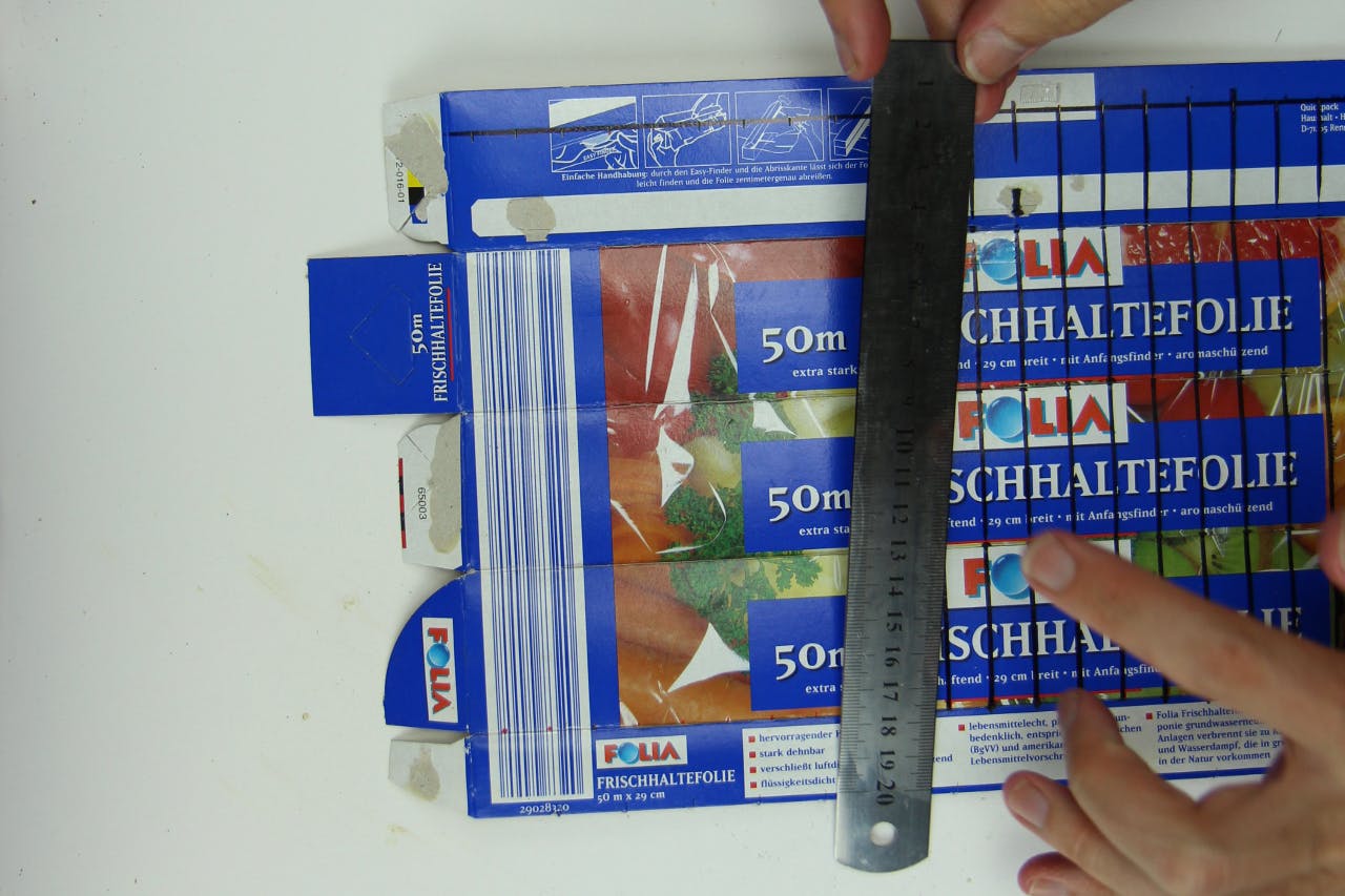
Start making the controller interface by marking where you want to attach the touch electrodes. Please note that they must not touch or overlap each other
Making the Controller Interface + Enclosure – Electrodes

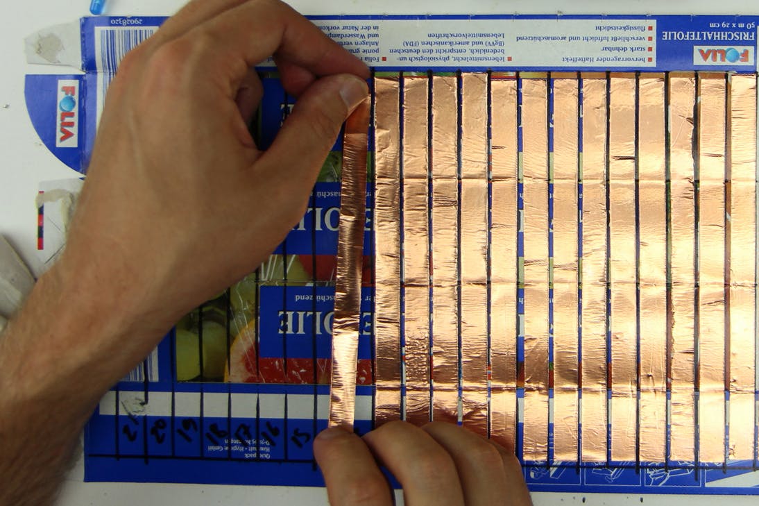
Next, cut the 24 copper electrodes to size and attach them to the enclosure
Making the Controller Interface + Enclosure – Plug


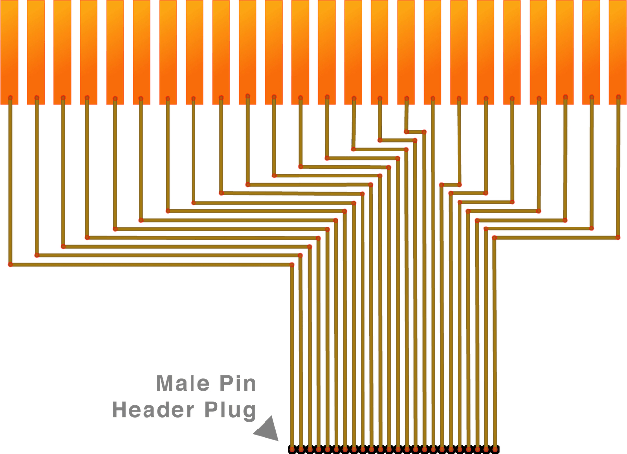
Now we can make the plug. For that cut a 2 * 24 hole wide perfboard and a24 pin male header to size and solder 24 cables to it. The cables in the middle should be at least 10 cm long. To the outside add the width of your electrodes plus the spacing in between for each cable. If for example you use 1 cm wide copper tape and leave 3 mm between the electrodes, your cable length should increase by 1.3 cm like this 10 / 11.3 / 12.6 / 13.9 / 15.2...
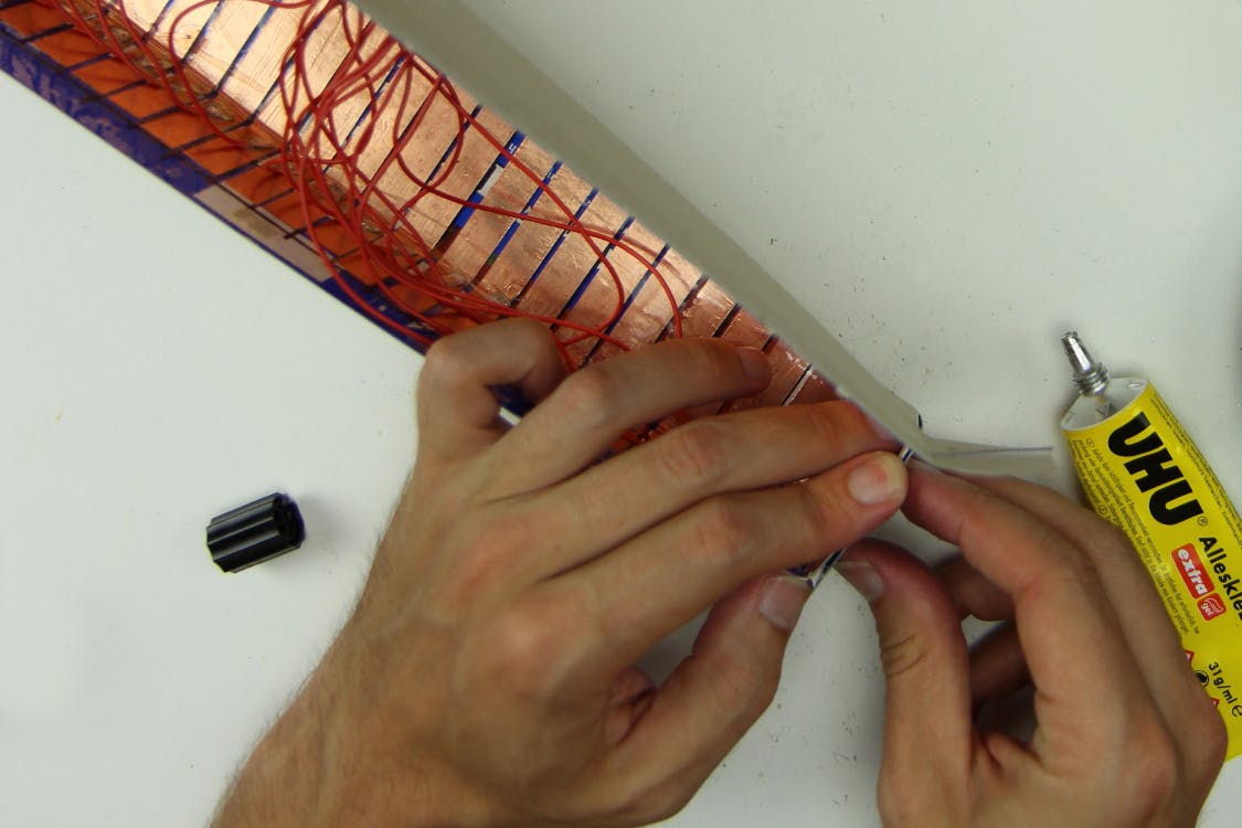
Then solder the other ends of the cables to the electrodes
Finish the interface by covering the copper surface with non-conductive adhesive tape
Making the Controller Interface + Enclosure – Fold a Box
Next fold the interface into a box and glue it
Making the Controller Interface + Enclosure – 2nd Box

Glue a smaller box to the box we made in the previous step. It later will contain the powerbank
Making the Controller Interface + Enclosure – Prepare the Controller-board

Cover the back of the controller board with some leftover cardboard or other slightly thicker non-conductive material
Making the Controller Interface + Enclosure – LED-Cutouts

Cut out holes for the LEDs and glue them and the powerbank (yellow object in the picture) in place. Make sure to place the powerbank in a way that you can still plug in and remove the USB-cable because that is how you turn your controller on and off. Also connect the touch-interface to the controller board and put it in the box. Most likely it will not move much, so you do not need to glue it in
Making the Controller Interface + Enclosure – USB Cable
Make a cut out for the USB-A to USB-C cable at the junction of the two boxes, pull it through and connect it to the Arduino Nano
The Finished Controller


Now the Controller is done!
You can close it with some rubber bands. If you later have problems with the sensors recognizing touch when there is none, try to put some non-conductive material like clingfilm or the like between the touch sensitive enclosure and the board and meandering cables. Also make sure to connect the powerbank when the touch sensitive part of the enclosure does not touch your hands or anything else (see the end of the instructable for explanation)
Making the Receiver Enclosure
In the next part of the instructable we will make an enclosure for the receiver as well. You will need another cardboard box (I chose one that contained a bluetooth transceiver before – fitting huh?) and some knobs for the potentiometers
Making the Receiver Enclosure – Cutouts

First cut out some circular holes for the potentiometers the LED. Also mak a cut out where you want to connect the USB-Cable to the Arduino Nano
Making the Receiver Enclosure – Glue in Receiver-board

Glue the Receiver board in. Make shure that the USB-C Jack of the Arduino Nano is aligned with the hole that you cut out for the cable connection in the step before
Making the Receiver Enclosure – Install Potentiometers + LED

Next glue in the LED and screw in all the potentiometers. The order how to put them in is the same as in the circuit diagram above
Making the Receiver Enclosure – Knobs

Attach the knobs
The Finished Receiver Enclosure

Connecting the Receiver to Pure Data – Externals

Now that all the hardware is finished, it's time to play some music with it! For that you need software that you can connect the hardware to. For Kravox that software is Pure Data Vanilla that you can download here for free
After installing Pure Data to your computer, start it and open the Kravox.pd file from the attachments. Please note that it needs to be saved on your computer in the same place as the drumsamples folder it comes with - otherwise Pure Data cannot find the samples
As soon as the Kravox.pd software interface has opened, look for a blue-info box (see picture) and install the four so-called externals that are listed in the box. Installing them is straightforward: Just click on "help" in the Pure Data Menu, choose "Find additional objects on the internet" (might be phrased slightly different), search for "comport", "zexy", "freeverb" and "arraysize" one by one and install the most recent version. Now the four objects labeled, comport, repack, freeverb and arraysize should have a solid outline like in the picture below. You might need to restart Pure Data for that though
Connecting the Receiver to Pure Data – Choosing the Right USB-Port

After installing the necessary externals you can connect the Receiver Box via USB. If you altered the code in Part 4 to use the Receiver with the Arduino Serial Monitor you need to undo this change first and upload the original code to the receiver's Arduino Nano before connecting and close the Arduino Serial Monitor, so the receiver is not busy trying to talk to it.
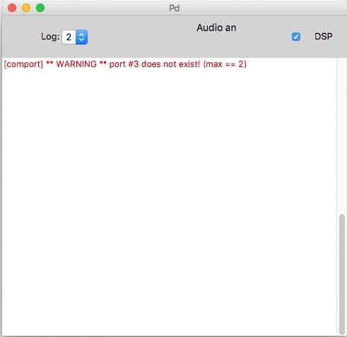
Now have a look at Pure Data's log / info window. If you see a rapidly updating data stream that's great because it means that pure data has already found the receiver, but most likely it will instead show you a red message like the one in the first picture that refreshes every other moment
The red message might be a little different, but the result is the same:
Pure Data did not yet succeed to connect to your receiver. That is because the program needs to be told, which USB port to listen to. USB-ports are sometimes a bit of a funny thing though: On a 2014 macbook Pro, Pure Data recognizes both USB ports as Serial Port 3, no matter to which you connect the receiver. In Milan I used Kravox with a Lenovo Yoga Pad with only one working USB-Port, that needed to be contacted as Serial Port 6, and recently installed it to another Windows Notebook with two USB-Ports, that wished to be addressed as Serial Ports 8 and 9... So my advice is just to try which number works with your USB-Port. For that I created a simple dialog as part of the Kravox.pd interface (See second picture), where you can just click through the numbers until one works. You can also try the "Show available ports" and "Show connected USB-devices" buttons – Sometimes, but not very often that also provides useful information. However it takes a while until you get a response in the info window
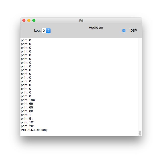
You will notice that you have found the right port number and that a
connection has been established when the info window shows a data stream like this that updates rapidly (See third window)
Connecting the Receiver to Pure Data – Turning on the Controller

Very good so far! Click save, so Pure Data will attempt to connect to this port the next time it opens automatically.
However we still need to turn the controller on. If you performed the optional step while making the controller-board and uncommented the last section of the Kravox Controller code to connect the controller to the Serial Monitor you should upload the original Version again now.
Connect the controller board to the powerbank. When you do this, the touch-interface-enclosure around the the board should be closed and the touch sensitive part of the enclosure should not touch your hands or anything else, as the touch sensors sense their environment when powered up and assume it to be the untouched state
You Are Done!
![Kravox And Guitar – Delivery [MUSIC VIDEO] wireless, pure data / Arduino multi-user-synthesizer](/proxy/?url=https://content.instructables.com/F6A/4RGL/JM0V4YM8/F6A4RGLJM0V4YM8.jpg&filename=Kravox And Guitar – Delivery [MUSIC VIDEO] wireless, pure data / Arduino multi-user-synthesizer)
Congratulations – You are done!
Have much fun playing Kravox!