LED CUBE 4X4X4 USING ARDUINO UNO
by The_Technocrat in Circuits > Arduino
44568 Views, 51 Favorites, 0 Comments
LED CUBE 4X4X4 USING ARDUINO UNO
![IMG_20170808_210140717.jpg](/proxy/?url=https://content.instructables.com/FW2/WTZI/J6IF27X6/FW2WTZIJ6IF27X6.jpg&filename=IMG_20170808_210140717.jpg)
![ewwwteg.jpg](/proxy/?url=https://content.instructables.com/FVE/UMRD/J6IF2EZ7/FVEUMRDJ6IF2EZ7.jpg&filename=ewwwteg.jpg)
![gfds.jpg](/proxy/?url=https://content.instructables.com/F55/EDVN/J6IF2BXH/F55EDVNJ6IF2BXH.jpg&filename=gfds.jpg)
![Screenshot_20170109-115726.png](/proxy/?url=https://content.instructables.com/F80/MGYM/IXLAL5R8/F80MGYMIXLAL5R8.png&filename=Screenshot_20170109-115726.png)
![ASDFGHM.jpg](/proxy/?url=https://content.instructables.com/FKW/H75A/J6IF267S/FKWH75AJ6IF267S.jpg&filename=ASDFGHM.jpg)
Hello !
In this Instructables we shall learn how to make a 4x4x4x LED Cube using Arduino. I have explained the making of the cube step by step in a sequence. The total cost of this project is 500 Rupees.
Watch this Video For Better understanding..
I have attached the link to the arduino code and the references from where i learned to make the cube. You can ask me what is the use of making this project....of course.. it's for decoration purpose only...but this can explain the smallest block of a 3D imaging system.
This cube requires 16 vertical LED rows and 4 horizontal layers. So the total required pins are 20. I have explained the working in detail in coming steps.
List of Materials
![IMG_20170305_205752057.jpg](/proxy/?url=https://content.instructables.com/F2R/9S84/J6IF0A3M/F2R9S84J6IF0A3M.jpg&filename=IMG_20170305_205752057.jpg)
![IMG_20170305_204933943.jpg](/proxy/?url=https://content.instructables.com/FLK/9CEK/J6IF09VS/FLK9CEKJ6IF09VS.jpg&filename=IMG_20170305_204933943.jpg)
![IMG_20170305_205900255.jpg](/proxy/?url=https://content.instructables.com/FG4/NC8N/J6IF0A4U/FG4NC8NJ6IF0A4U.jpg&filename=IMG_20170305_205900255.jpg)
![IMG_20170222_210343251.jpg](/proxy/?url=https://content.instructables.com/FST/E3W5/IZ6COUG0/FSTE3W5IZ6COUG0.jpg&filename=IMG_20170222_210343251.jpg)
![IMG_20161001_095141307.jpg](/proxy/?url=https://content.instructables.com/FS8/CIFQ/IWH3AW43/FS8CIFQIWH3AW43.jpg&filename=IMG_20161001_095141307.jpg)
![qwertyu.jpg](/proxy/?url=https://content.instructables.com/FSO/TO5S/J6IF26ZL/FSOTO5SJ6IF26ZL.jpg&filename=qwertyu.jpg)
![IMG_20170305_204011666.jpg](/proxy/?url=https://content.instructables.com/FHX/OISP/J6IF09QO/FHXOISPJ6IF09QO.jpg&filename=IMG_20170305_204011666.jpg)
![edit.jpg](/proxy/?url=https://content.instructables.com/FRN/ZOD1/IWH3AVQ7/FRNZOD1IWH3AVQ7.jpg&filename=edit.jpg)
Arduino UNO
Diffused LED 4mm (64 nos)
220 ohm resistor (Color Code: Red-Red-Brown)
Soldering kit ( Iron,Solder,Flux..)
General Purpose PCB
Wires
Wire stripper,
Nose Pliar
Terminal Strip
Drill
Hot Glue Glue
3mm Ply-wood
Hexa Blade
Stationaries like Scale, Marker,etc
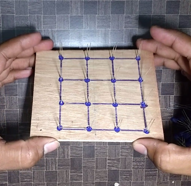
Preparation of Jig to Place the LED
![IMG_20170305_220932954.jpg](/proxy/?url=https://content.instructables.com/F4K/HW7K/J6IF0A8K/F4KHW7KJ6IF0A8K.jpg&filename=IMG_20170305_220932954.jpg)
![IMG_20170305_220945526.jpg](/proxy/?url=https://content.instructables.com/FMB/TNHP/J6IF0A9O/FMBTNHPJ6IF0A9O.jpg&filename=IMG_20170305_220945526.jpg)
The jig helps to place the LEDs in place and helps in soldering.
Find some Ply-Wood and use a marker to mark the position of LEDs. The LEDs should be placed 1 inch apart.
Use a Drilling machine to drill 4mm holes in the marked places.
Placing the LEDs on the Jig and Soldering.
![IMG_20170316_225045697.jpg](/proxy/?url=https://content.instructables.com/F5Z/4RSR/J6IF0ACA/F5Z4RSRJ6IF0ACA.jpg&filename=IMG_20170316_225045697.jpg)
![IMG_20170316_225107613.jpg](/proxy/?url=https://content.instructables.com/FW9/GLCJ/J6IF0AG3/FW9GLCJJ6IF0AG3.jpg&filename=IMG_20170316_225107613.jpg)
![IMG_20170316_225054482.jpg](/proxy/?url=https://content.instructables.com/FJA/2SHE/J6IF0AEW/FJA2SHEJ6IF0AEW.jpg&filename=IMG_20170316_225054482.jpg)
![qwertyu.jpg](/proxy/?url=https://content.instructables.com/FMU/TW17/J6IEXLYM/FMUTW17J6IEXLYM.jpg&filename=qwertyu.jpg)
![cfvbrtm.jpg](/proxy/?url=https://content.instructables.com/F0I/QLFV/J6IEXM4U/F0IQLFVJ6IEXM4U.jpg&filename=cfvbrtm.jpg)
![trfvvv.jpg](/proxy/?url=https://content.instructables.com/FMH/GAJG/J6IEXM34/FMHGAJGJ6IEXM34.jpg&filename=trfvvv.jpg)
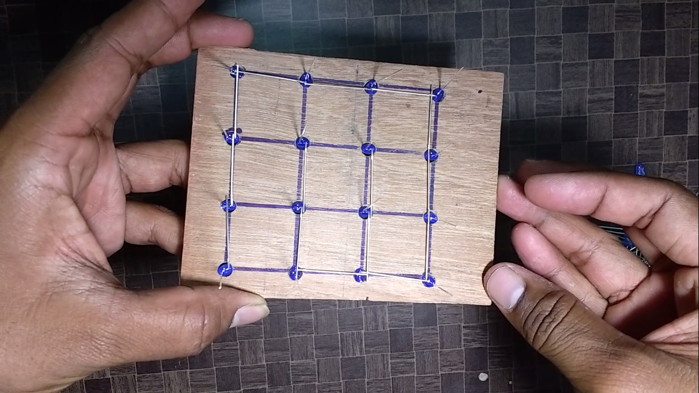
Use a 3 volt cell to check the working of LEDs before proceeding.
Place 16 LEDs on the jig placed on a table. Bend the positive leads of the LEDs to interconnect the Positive terminals of all the LEDs. The leads facing upwards towards you will be Negetive. Watch my video for better understanding.
You need not worry if you did the opposite way. You will only have to make small changes in Arduino code.
Apply small portion of flux on each joint and solder the joints to interconnect all the positive leads (Bent leads) .
This is your first layer. You will have to make similar 4 of these.
Solder the 4 Layers
![IMG_20170801_231748123.jpg](/proxy/?url=https://content.instructables.com/FM3/R5ZV/J6IEXLXG/FM3R5ZVJ6IEXLXG.jpg&filename=IMG_20170801_231748123.jpg)
![dwetr.jpg](/proxy/?url=https://content.instructables.com/FVT/RW1B/J6IEXM6O/FVTRW1BJ6IEXM6O.jpg&filename=dwetr.jpg)
![IMG_20170801_231632610.jpg](/proxy/?url=https://content.instructables.com/FEO/188I/J6IEXM9Q/FEO188IJ6IEXM9Q.jpg&filename=IMG_20170801_231632610.jpg)
![IMG_20170801_231627273.jpg](/proxy/?url=https://content.instructables.com/FHW/PNG7/J6IEXM9O/FHWPNG7J6IEXM9O.jpg&filename=IMG_20170801_231627273.jpg)
![SFDV.jpg](/proxy/?url=https://content.instructables.com/F1Z/331M/J6IF0AIH/F1Z331MJ6IF0AIH.jpg&filename=SFDV.jpg)
![h vcx.jpg](/proxy/?url=https://content.instructables.com/FNY/5J96/J6IEXM8H/FNY5J96J6IEXM8H.jpg&filename=h vcx.jpg)
![v d.jpg](/proxy/?url=https://content.instructables.com/FJO/WRIE/J6IEXM49/FJOWRIEJ6IEXM49.jpg&filename=v d.jpg)
![dsf.jpg](/proxy/?url=https://content.instructables.com/FAQ/SYUD/J6IF0DZW/FAQSYUDJ6IF0DZW.jpg&filename=dsf.jpg)
![dsfvccx.jpg](/proxy/?url=https://content.instructables.com/F7R/RW7J/J6IEXM5F/F7RRW7JJ6IEXM5F.jpg&filename=dsfvccx.jpg)
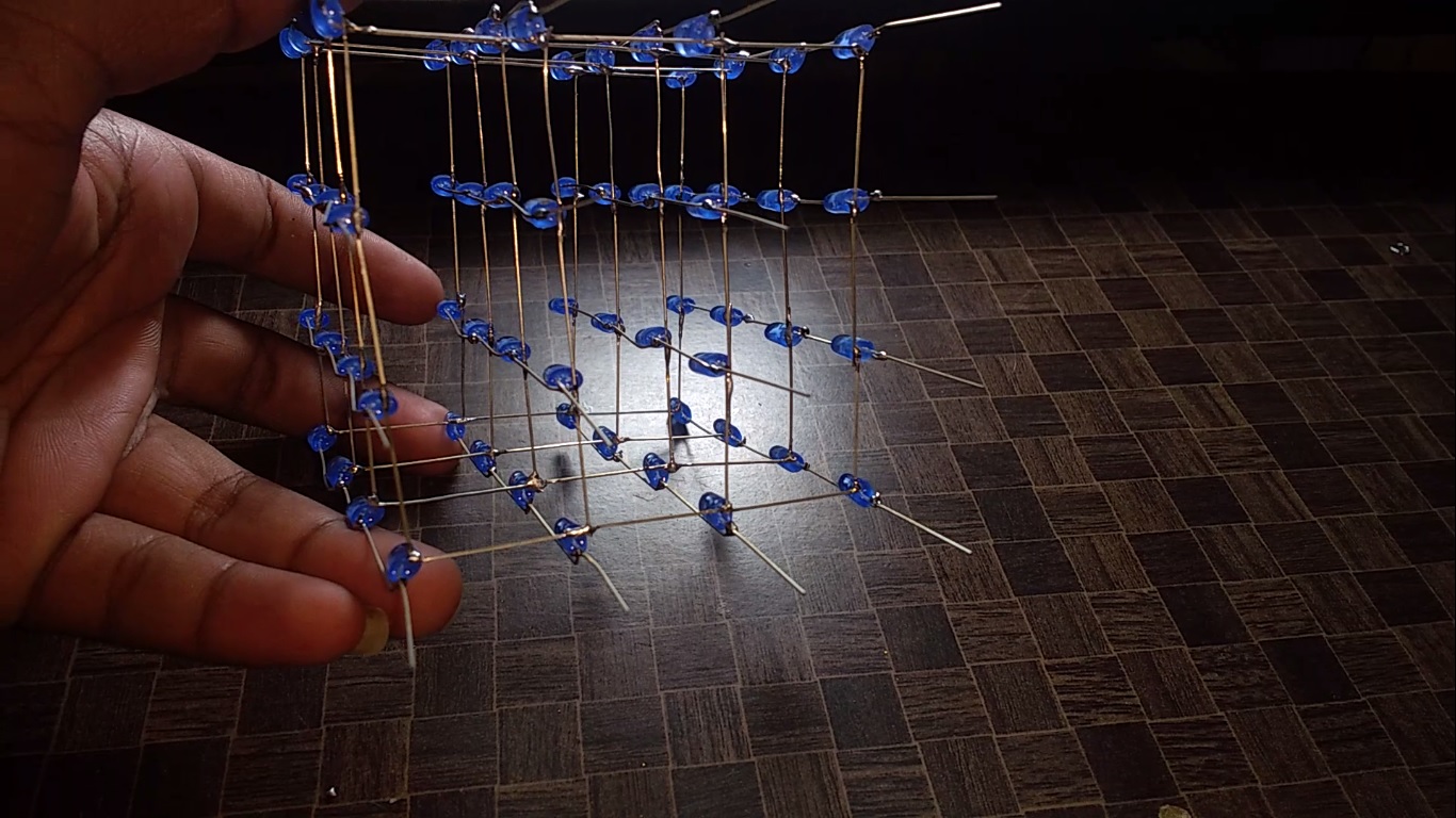
Let's name the four layers as A,B,C and D.
In this step we shall attach the four layers. Now we will have to connect the vertical pins(Negative Polarity) of each layer.
Start by soldering the corner pins of each layer one after the other. Apply required amount of flux and solder the vertical terminals.
Insert the Cube into the PCB and Solder the pins.
Strip the insulation of a single strand wire. Connect these wires on to four layers(Positive Terminals) and the other end is connected to PCB.
Connect 220 ohm resistors to these 4 layer connections.
Wiring the LED Cube to Arduino.
![dsfvccx.jpg](/proxy/?url=https://content.instructables.com/F74/XIO8/J6IF23Z1/F74XIO8J6IF23Z1.jpg&filename=dsfvccx.jpg)
![DAWREWG.jpg](/proxy/?url=https://content.instructables.com/FLY/4KCQ/J6IF0AHA/FLY4KCQJ6IF0AHA.jpg&filename=DAWREWG.jpg)
![Sfghf.jpg](/proxy/?url=https://content.instructables.com/FPJ/95JA/J6IEXM0V/FPJ95JAJ6IEXM0V.jpg&filename=Sfghf.jpg)
![IMG_20170820_203541253.jpg](/proxy/?url=https://content.instructables.com/FP8/JBTJ/J6IF266Q/FP8JBTJJ6IF266Q.jpg&filename=IMG_20170820_203541253.jpg)
![assasas.jpg](/proxy/?url=https://content.instructables.com/FY9/IDQQ/J6IF280E/FY9IDQQJ6IF280E.jpg&filename=assasas.jpg)
![IMG_20170820_203722464.jpg](/proxy/?url=https://content.instructables.com/FTD/TVJ0/J6IF267F/FTDTVJ0J6IF267F.jpg&filename=IMG_20170820_203722464.jpg)
![ASDFGHM.jpg](/proxy/?url=https://content.instructables.com/FKW/H75A/J6IF267S/FKWH75AJ6IF267S.jpg&filename=ASDFGHM.jpg)
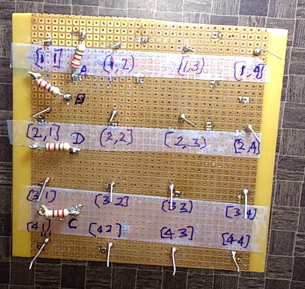
Before wiring it is essential to know the terminal names.
Imagine holding the cube and seeing from the top. Consider a corner LED and that is your reference. Corner towards right becomes your 'x' axis and the other becomes 'y'axis.
I have named the pins and terminals after connecting on PCB.(Refer to the image)
Solder each wire to the terminal strip and hot glue it to avoid the breakage of solder joints.
The following is the connection details. Example: Pin Name (1,1) goes to Digital pin 13 on Arduino.
[(x,y)-Pin]
(1,1)-13
(1,2)-12
(1,3)-11
(1,4)-10
(2,1)-9
(2,2)-8
(2,3)-7
(2,4)-6
(3,1)-5
(3-2)-4
(3-3)-3
(3,4)-2
(4,1)-1
(4,2)-0
(4,3)-A5
(4,4)-A4
Layers [Layer-Pin]
a-A0
b-A1
c-A2
d-A3
I made a Small simple wooden casing to hide the wiring. Cut required size ply-wood and hot glue them to form a Box.
​Programming the Arduino
![ardnpdkv.jpg](/proxy/?url=https://content.instructables.com/FF3/HHQ6/J6IF21YR/FF3HHQ6J6IF21YR.jpg&filename=ardnpdkv.jpg)
![sdxvbv.jpg](/proxy/?url=https://content.instructables.com/FZ1/WGIK/J6IF21WK/FZ1WGIKJ6IF21WK.jpg&filename=sdxvbv.jpg)
![ghjbv.jpg](/proxy/?url=https://content.instructables.com/FGI/WSS8/J6IF21UB/FGIWSS8J6IF21UB.jpg&filename=ghjbv.jpg)
![mn dfgh.jpg](/proxy/?url=https://content.instructables.com/FVY/2ZR1/J6IF21UP/FVY2ZR1J6IF21UP.jpg&filename=mn dfgh.jpg)
![IMG_20170808_210140717.jpg](/proxy/?url=https://content.instructables.com/FW2/WTZI/J6IF27X6/FW2WTZIJ6IF27X6.jpg&filename=IMG_20170808_210140717.jpg)
Note: The code uploaded here is not Designed by me. View the Original Code HERE.
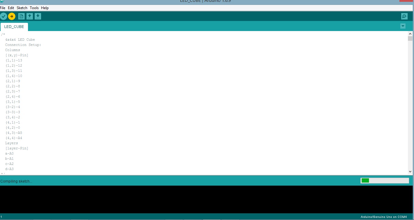
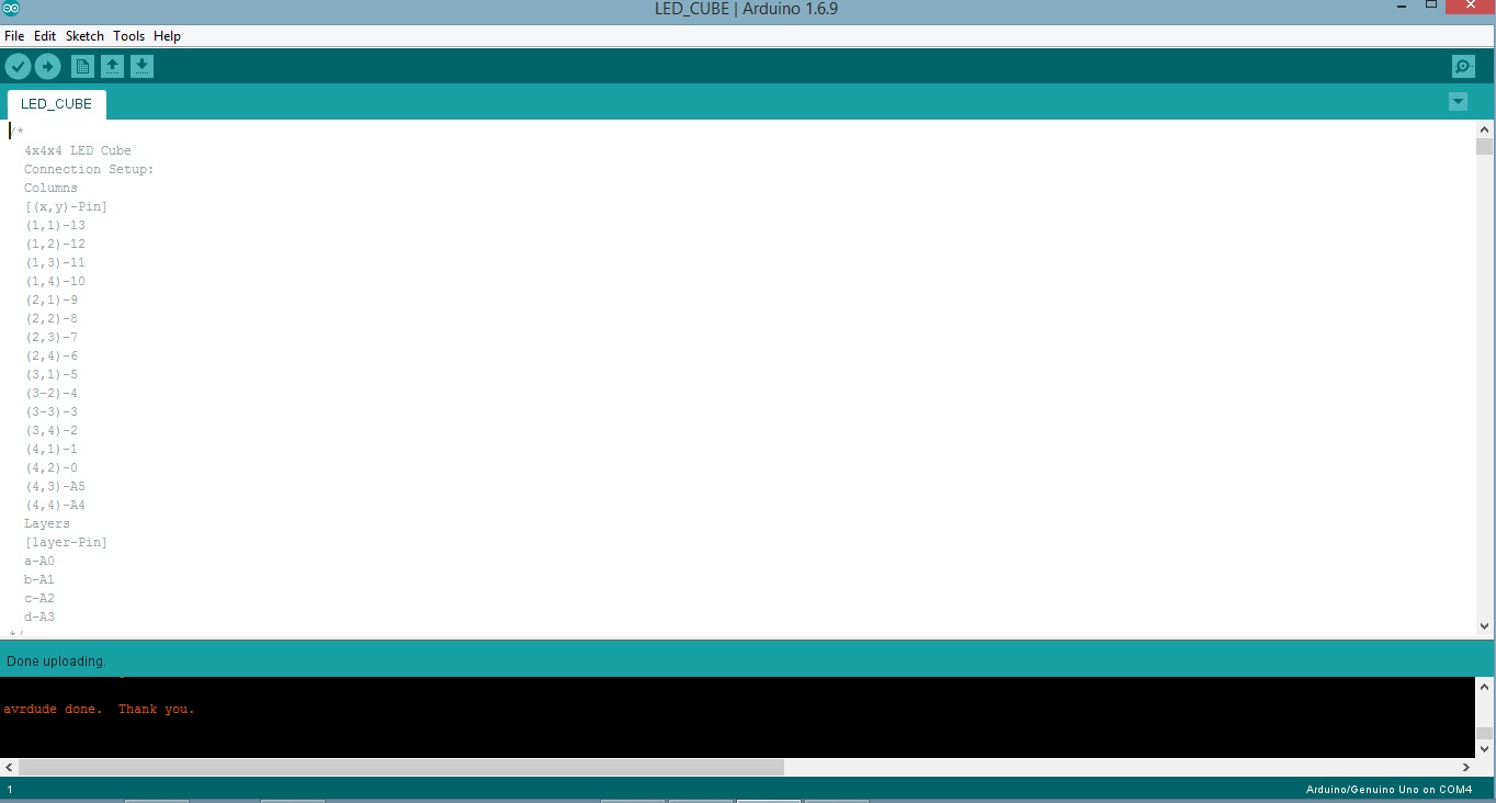
Download the Code and open it in Arduino software.
Connect the arduino to your PC USB port.
Select the Correct Port and your Arduino Board.
Upload the code and your done!
You can power your Arduino using a mobile phone charger.
The Link for the Code from the Creator
Downloads
Working Video and References
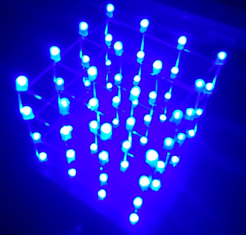
![LED Cube | 4x4x4 LED Cube](/proxy/?url=https://content.instructables.com/F6E/6EHJ/J6IF1ZDP/F6E6EHJJ6IF1ZDP.jpg&filename=LED Cube | 4x4x4 LED Cube)
![wertgvcxz.jpg](/proxy/?url=https://content.instructables.com/FNQ/RRRY/J6IF2BWO/FNQRRRYJ6IF2BWO.jpg&filename=wertgvcxz.jpg)
Congragulations!!
You made yourself a Cool looking LED CUBE to place on a corner of your Desk..!
Watch the Full working video from here.
References
https://www.instructables.com/id/4x4x4-LED-Cube-A...
https://playground.arduino.cc/Main/ArduinoPinCurre...
Thank you very much for checking out my Instructables
If you have any quires , please feel free to post the questions and comments in Section below.
H S Sandesh Hegde
Bengaluru, INDIA