LED Circuit Sculpture


While surfing on social media I got to know about circuit sculpture where in we create freeform structure out of electronic components which resemble real life objects. It can anything like a car, tree, humanoid object or even a satellite.
These sculptures can be used to give user some data in fancy way or even can used as decorative piece to keep in your home as I did.
The Idea


The idea is to use LEDs of single color to display some interesting animations.
LEDs will be the standard 0805 package mono color blue LEDs, smaller package means more LEDs.
To control LEDs, max7219 module will be used which uses multiplexing method to control large number of LEDs.
And finally, to tell max7219 module how to control the LEDs we have Arduino Nano.
Supplies
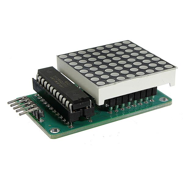
Electronic components:
- Arduino nano (with unsoldered headers) X 1
- Max7219 module X 1
- 0805 blue color LED X 64
Materials:
- Single strand wire
- Enameled copper wire
- Male headers
- Solder wire
- Mini b USB cable
Tools:
- Soldering iron
- Wire cutter
- Sandpaper (to remove enamel coating for soldering purpose)
- 15cm scale (to measure length of wire to cut)
- Tweezer/your hand (to hold small thing)
- Plier
Few Notes on Electronics Components
1. max7219 module
Max7129 can single handedly control up to 64 LEDs. It uses SPI protocol to communicate with a uController and can lit every kind of generic LED having forward voltage range from 1.5v (red) to 3.3v (blue) these factors make it suitable for our project.
The module with green PCB is what we need because the dot matrix as well as the max7219 ic can be removed which we will do so and replace the dot matrix with our custom LED display which we will create.
2. LED
We will use blue color LED, why blue? Because I feel blue is the coolest color and is perfect for home decor.
0805 package is perfect for soldering purpose, not too big and not too small.
3. uController
Any uController would be fit for this project as we only need the SPI pins of the uController. Arduino nano fits perfect because most people are familiar with this board and easy to program using Arduino ide as has a USB to serial chip (CH340) embedded in board itself.
The Design


The design of the sculpture will be like a satellite, this may sound crazy but is fun.
The most common structure of any satellite is that it has 2 or 2 or more solar panels for power and a central pod which has all the main functional things like the communications, sensors. The design I am going to use is shown in the picture above. The 2 solar panels will be replaced by LED module which we will create. And the central part of the satellite will be replaced by our uController and display driver (max7219).
The LED Module

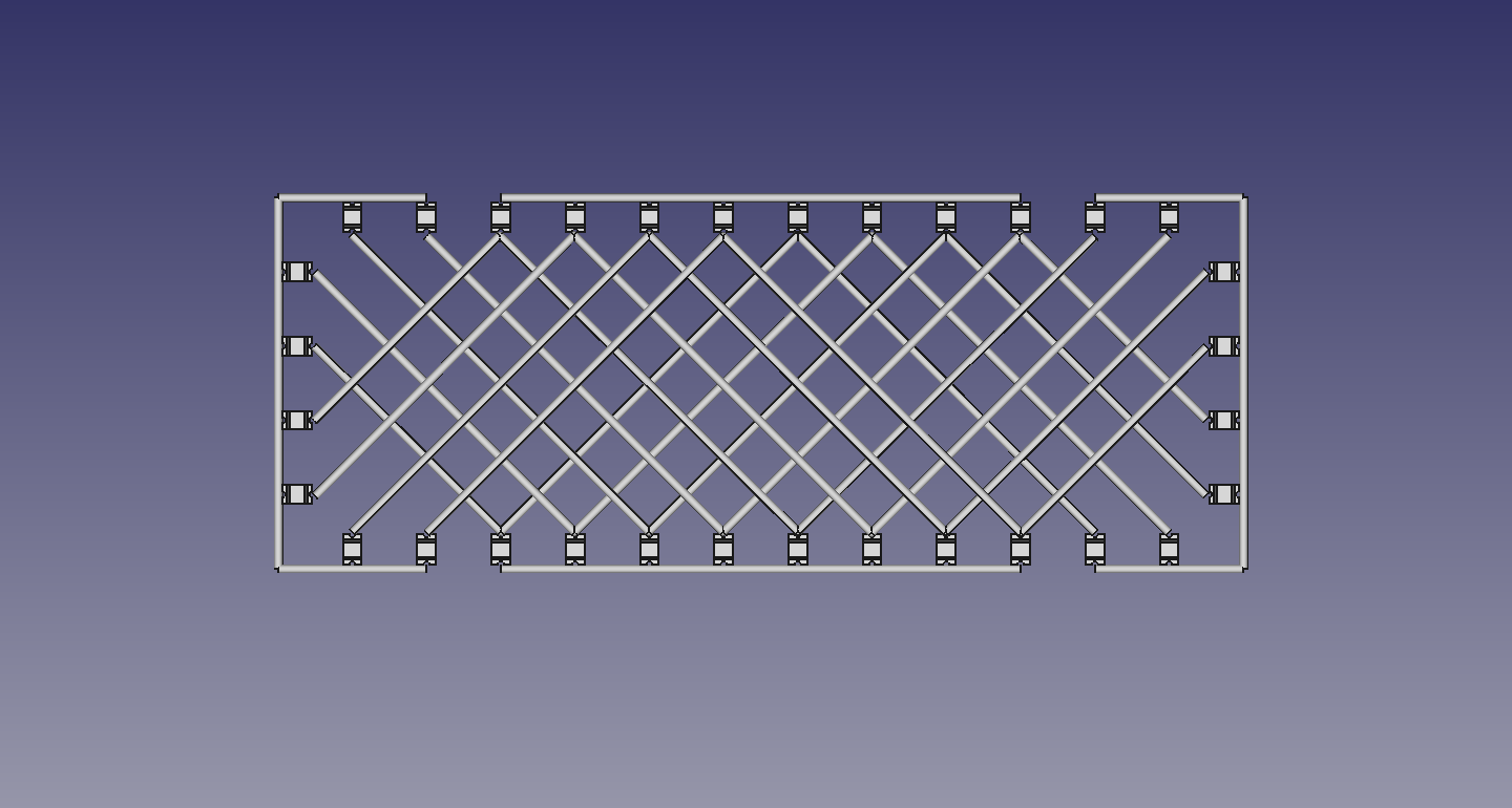

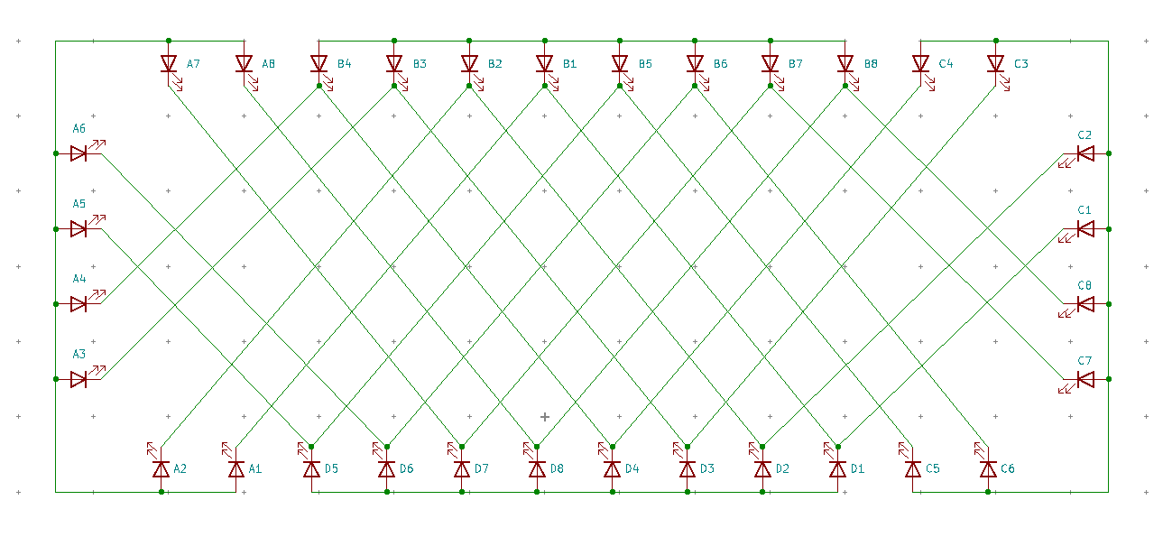


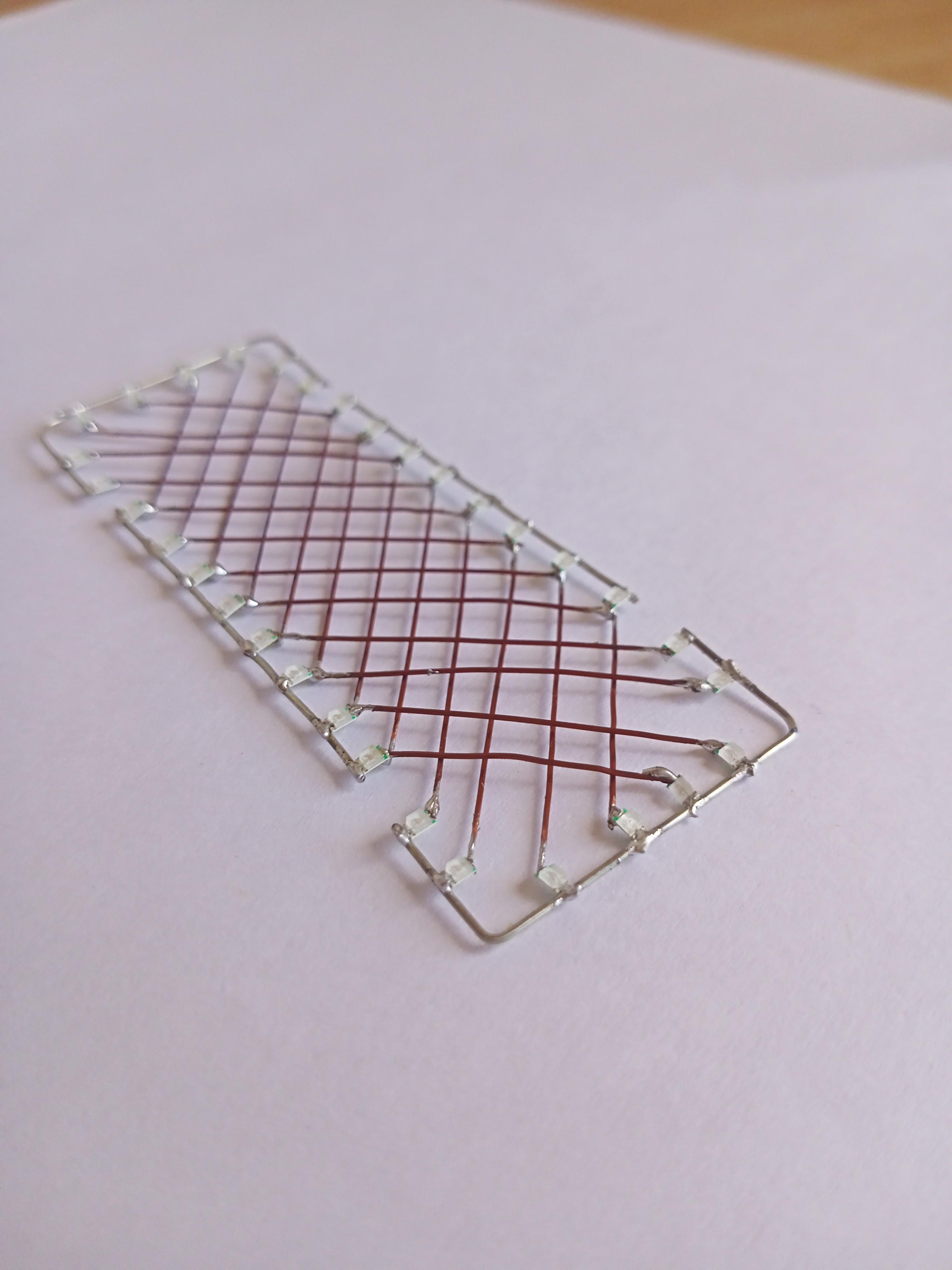

As max7219 can drive at most 64 LEDs and we have two panels therefore 32 LEDs will make a single module.
Build process for both the panels will be same.
The setup goes like this, as we 32 LEDs => 4 X 8 matrix, so the +ve of 8 each LEDs will be joined together and -ve of 4 each LEDs will be joined together (remaining 4 will come from 2nd LED module).
The process
- Using a template to solder and bends is very helpful. I have attached a pdf file which you print it out on A4 size paper and use it
- Prepare single strand wire by remove the insulation and cut out wire of length 2 x 35mm, 2 x 45mm.
- Bend the 45mm wire into C shape the bends be at 10mm from end points.
- These will act as framework for our module.
- Now solder LED to the wire segments with a distance of 5mm in between each LED– make sure that positive of LEDs is soldered to wire and not negative, also in case of C part they should be facing inwards.
- This way we have successfully connected positive of eight LEDs to each now we need to connect negative of every 4 LEDs.
- Cut out enameled copper wire according to dimensions given in picture - enameled is necessary as it avoids electrical connections even when both wires are toughing each other
- Sand out ends of each wire so we can solder them.
- Now this might be a confusing step as there are a lot of connections to make, I refer each LED by a specific notation do refer the picture above.
- Connect A1 to B1, B1 to D1, D1 to C1.
- Then A2 to B2, B2 to D2, D2 to C2.
- Then A3 to B3, B3 to D3, D3 to C3 using enameled copper wire.
Now you must have understood the pattern likewise solder every LED.
Note that in the pictures even if the wires overlap each other but they are electrically isolated.
Do create a 2nd module using same instructions.
Downloads
The UController Module

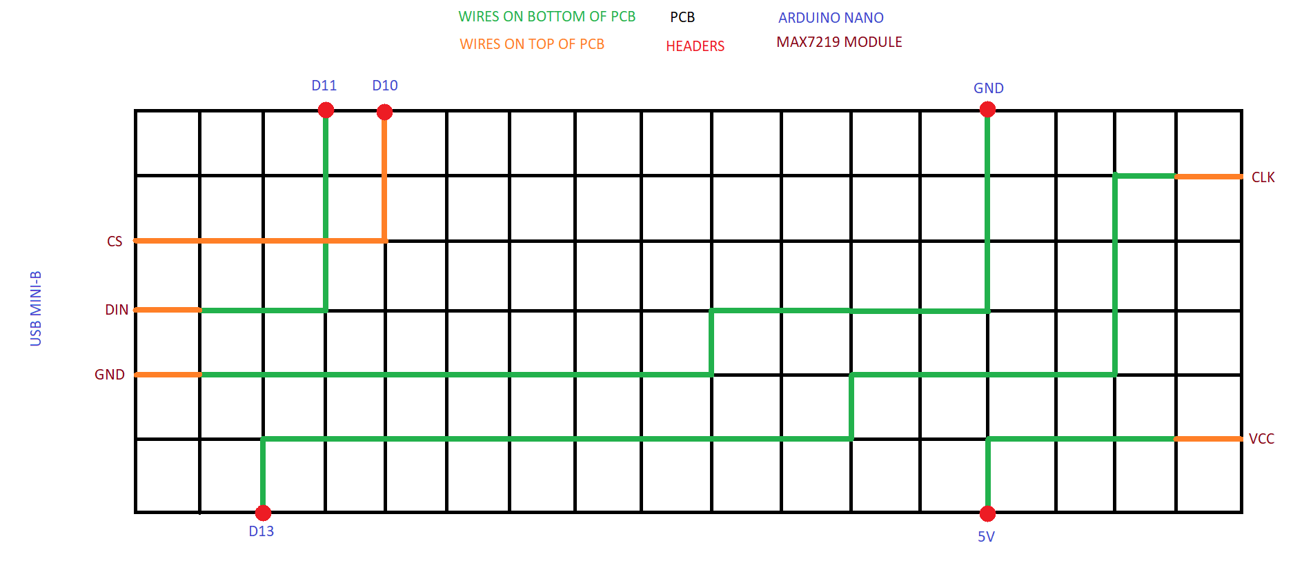


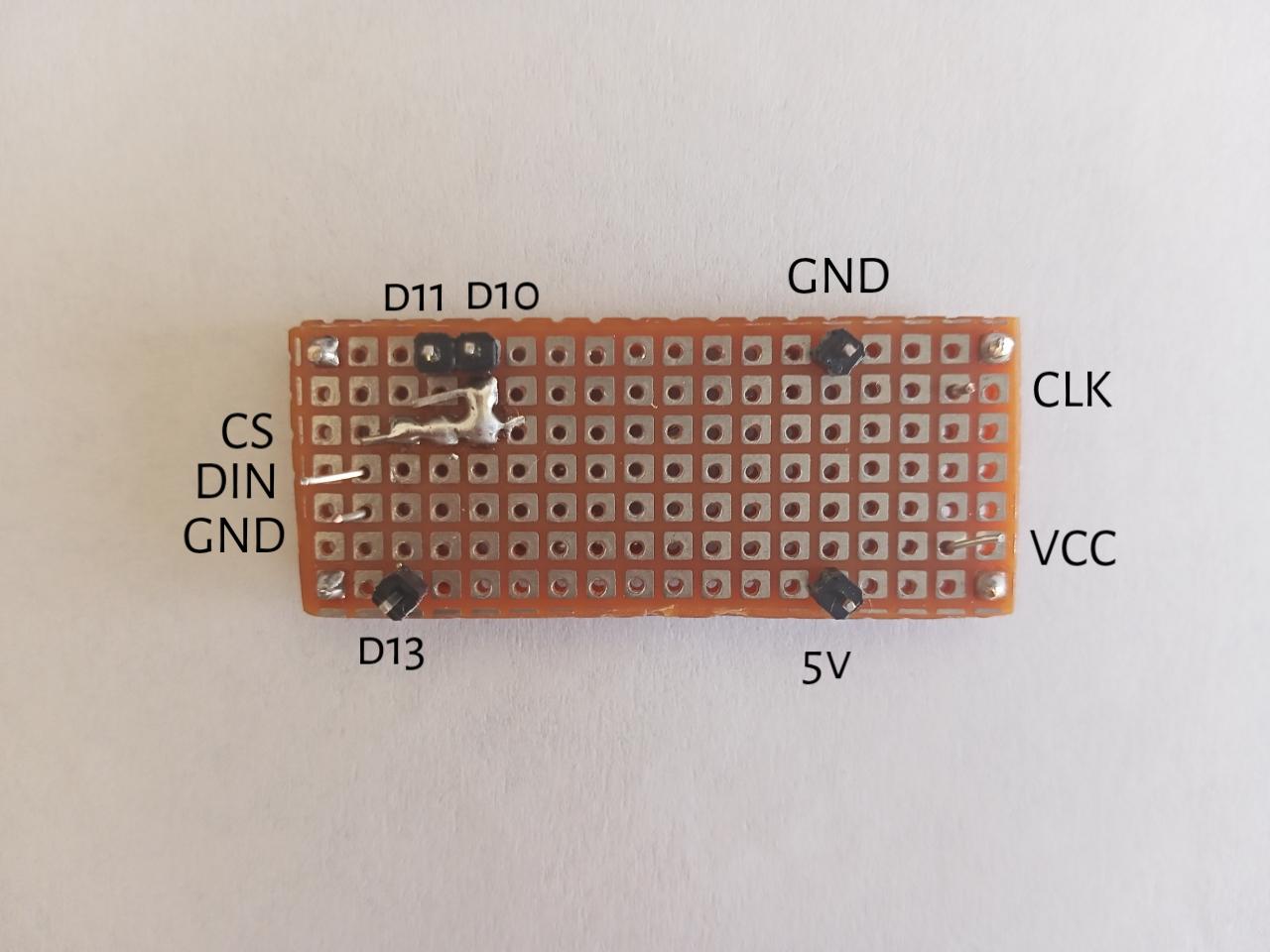
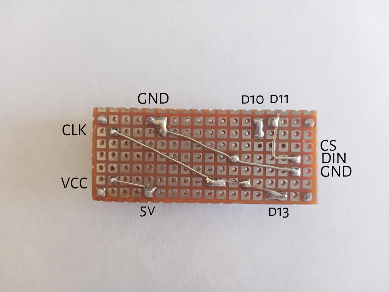


Double side PCB is ideal for this process but sadly I din't had in stock so what I did instead is joined two single layer zero PCB.
We need double side PCB because it will be used to join Arduino nano on bottom and max7219 on top.
Now you might wonder how it is possible to solder two THT module on a single PCB, cause when we solder a THT component it is inserted through one end, solder on other and when we try to solder component on another sider the first component will block its pins.
To solve this dilemma, we will use the holes on Arduino nano (this is the reason why we need unsoldered headers on Arduino nano).
Through the process it will get clear.
The process
- First cut out a 7 X 18 (holes) PCB – if using single side PCB to convert into double we need 2 of them.
- Now to join the two single side PCB solder a single header on four corner of the PCB. 4 should be enough to hold down together also make sure that the solder pads are facing outwards and not inwards.
- Take 5 male headers and solder them to the PCB, the black spacer should be facing towards you if the 2 consecutive headers are on top left corner when you look the PCB from above– it is very well shown in the diagram above where to solder.
- Now solder single strand wire to the PCB according to the picture – this way we bring out the connections to connect max7219 module.
- Now we need to desolder the bent headers on max7219 module and solder new ones so that these can be used to connect to our PCB.
- To desolder – straighten the bend wire using a plier – remove the black spacers, same can be done by plier, now desolder individual header.
- I am using single strand wire instead of headers because they can be soldered individually and are easily bendable.
- When we desoldered the headers, the holes must have filled with solder so in that case, hold soldering iron just touching a hole as the solder starts to melt quickly insert wire from other side this way, we can insert the wire even if holes are filled with solder.
- Solder max7219 module to PCB according to the picture above – use the wires we soldered previously.
- Now solder Arduino nano to PCB – use the headers we soldered previously, if the two consecutive headers are at top left corner, then the mini-USB cable of Arduino nano should be to the left and uController side should face towards you.
Doing so we connected:
Max7219 module -> Arduino nano
VCC -> 5V
GND -> GND
DIN -> D11
CS -> D10
CLK -> D13
Now that Arduino nano and max7219 are joined together we can attach the LED modules to max7219 module to complete the hardware part.
Resistor of LED
When it comes to LED there is a talk of maximum current through the LED
In max7219 the current through all LEDs is controlled by single a resistor which is connected between VCC and Iset pin of max7219 this is the reason why the color (forward voltage) of every LED in the matrix should be same
A 10k resistor is used by the manufacturer for the red dot matrix, we do not need to swap the resistor because a 10k gives nice lower brightness with blue color which is acceptable.
The Assembly


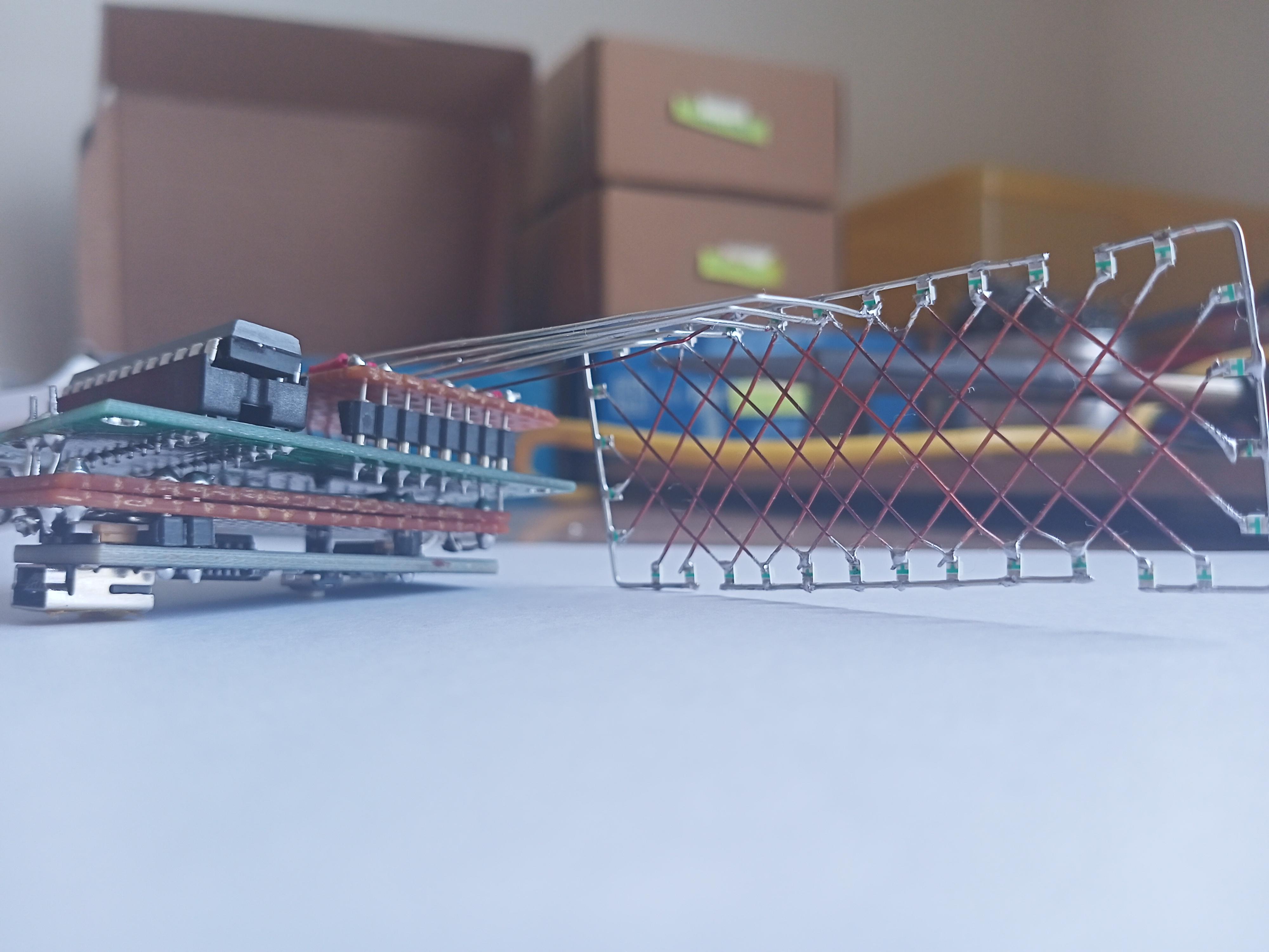


Now is the time to join the 2 LED modules to the uController module
There are total of 12 connections coming out of a single LED module (8 from -ve and 4 from +ve) of which 8 are common to the 2nd LED module (-ve ones)
Now soldering 16 pins in mid air will be quiet challenging also the pin numbering of the dot matrix is not in numerical order, it’s a bit random, which can lead to unnecessary electrical connections, so what I did instead is, I slipped a zero PCB between the female headers on board and wires from LED modules, this way we can rearrange the pins of female headers on zero PCB and solder the wires from LED module to the PCB
Another thing to consider is that the female headers on the max module are not compatible with pins of zero PCB they are slightly offset so we need to use single strand wires which are easily bendable.
The process
- Cut out a 10 x 11 holes zero PCB.
- Now cut 8 of about 7mm single strand wire – we will solder 8 of them at a go.
- In male headers we have black spacers which hold all the pins together while soldering but to solder single strand we will use the female header on board itself
- Insert all eight wires in the female headers.
- Place the zero on the wires and solder them.
- Similarly solder remaining 8 wires on the opposite side – the wires will bend a little because of the offset.
- Now bring all the negative part to the middle of PCB using wires – this way all the -ve parts will be equidistant to both LED modules.
- Now cut out single strand wire of length according to the template – these should be 8 L shaped wires of increasing length.
- Then solder these L wires to LED modules, the smallest goes to -ve of B8 and the longest goes to -ve of B4.
pins of matrix -> pins of female headers
1 -> 12
2 -> 14
3 -> 2
4 -> 1
5 -> 5
6 -> 7
7 -> 8
8 -> 9
Now to solder the LED module to mid part of PCB where we brought the pins of female headers using wires.
10. Now solder the 4 positive of LED module using enameled wire
It should go like this
A -> pin 4
B -> pin 6
C -> pin 10
D -> pin 3
11. Similarly solder the 2nd module but the -ve lines will be mirrored, -ve of E8 will have the smallest and -ve of E4 will have the longest wire.
12. Solder +ve of the remaining with enameled wire
Which goes like
E -> pin 13
F -> pin 11
G -> pin 15
H -> pin 16
Downloads
The Code
Now that we have completed the assembly part, its time to program Arduino nano to display beautiful animations.
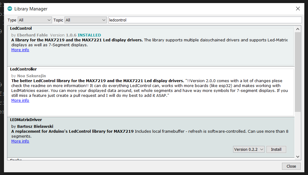
I used a library named LEDControl by Eberhard Fahle. Using this library, we can control individual LEDs and create our own custom animations. LEDs can be controlled by just few functions.
LEDControl lc=LEDControl(11,13,10,1);
This line initializes the communication between Arduino and max7219.
The four parameters are as follows:
- pin 11 connects to DIN of the MAX7219.
- pin 13 connects to CLK of the MAX7219.
- pin 10 connects to pin CS of the MAX7219.
- The number of MAX7219s connected. Which is one in our case
lc.shutdown(0,false);
lc.setIntensity(0,8);
The first line above turns the LEDs connected to the MAX7219 on. If you set TRUE, you can send data to the MAX7219, but the LEDs will stay off. The second line adjusts the brightness of the LEDs in sixteen stages. For both of those functions (and all others from the LEDControl) the first parameter is the number of the MAX7219 connected. If we have one, the parameter is zero… for two MAX7219s, it is 1 and so on.
lc.setLED(0,col,row,true);
this function turns on an LED positioned at col, row connected to MAX7219 #1. Change TRUE to FALSE to turn it off.
So to turn on A1 LED col, row will be 3,2 you can refer the following matrix.
A1 -> (3,2) A2 -> (1,2) A3 -> (6,2) A4 -> (4,2) A5 -> (7,2) A6 -> (5,2) A7 -> (2,2) A8 -> (2,2)
B1 -> (3,4) B2 -> (1,4) B3 -> (6,4) B4 -> (4,4) B5 -> (7,4) B6 -> (5,4) B7 -> (2,4) B8 -> (2,4)
C1 -> (3,3) C2 -> (1,3) C3 -> (6,3) C4 -> (4,3) C5 -> (7,3) C6 -> (5,3) C7 -> (2,3) C8 -> (2,3)
D1 -> (3,1) D2 -> (1,1) D3 -> (6,1) D4 -> (4,1) D5 -> (7,1) D6 -> (5,1) D7 -> (2,1) D8 -> (2,1)
E1 -> (3,0) E2 -> (1,0) E3 -> (6,0) E4 -> (4,0) E5 -> (7,0) E6 -> (5,0) E7 -> (2,0) E8 -> (2,0)
F1 -> (3,5) F2 -> (1,5) F3 -> (6,5) F4 -> (4,5) F5 -> (7,5) F6 -> (5,5) F7 -> (2,5) F8 -> (2,5)
G1 -> (3,6) G2 -> (1,6) G3 -> (6,6) G4 -> (4,6) G5 -> (7,6) G6 -> (5,6) G7 -> (2,6) G8 -> (2,6)
H1 -> (3,7) H2 -> (1,7) H3 -> (6,7) H4 -> (4,7) H5 -> (7,7) H6 -> (5,7) H7 -> (2,7) H8 -> (2,7)
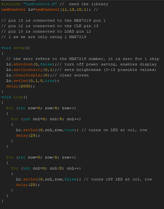
Following is a test code.
#include "LEDControl.h"
// need the library

LEDControl lc=LEDControl(11,13,10,1);
// pin 11 is connected to the MAX7219 pin 1
// pin 13 is connected to the CLK pin 13
// pin 10 is connected to LOAD pin 12
// 1 as we are only using 1 MAX7219

void setup()
{
  // the zero refers to the MAX7219 number, it is zero for 1 chip
  lc.shutdown(0,false);// turn off power saving, enables display
  lc.setIntensity(0,8);// sets brightness (0~15 possible values)
  lc.clearDisplay(0);// clear screen
}

void loop()
{
  for (int row=0; row<8; row++)
  {
    for (int col=0; col<8; col++)
    {
      lc.setLED(0,col,row,true); // turns on LED at col, row
      delay(25);
    }
  }
  for (int row=0; row<8; row++)
  {
    for (int col=0; col<8; col++)
    {
      lc.setLED(0,col,row,false); // turns off LED at col, row
      delay(25);
    }
  }
The Done!


LED sculpture is ready!
To power, plug the USB mini b to a 5v wall adapter or even to a computer as power consumptions are below maximum rating of a computer.