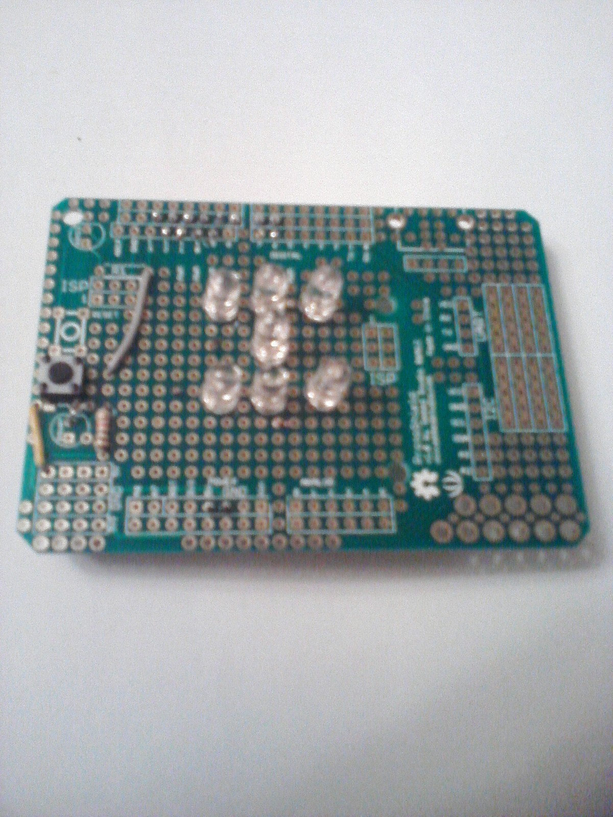
LED Die With Arduino


This project is a die that you will do with 7 LEDs, 8 resistors and a small switch. Once you construct the die, you will connect it to an Arduino hardware to download the program and you can utilize the die by manipulating a small switch.
Or you can use a Protoshield Kit for Arduino and assemble your LED die on it.
Copy and Paste the next websites to see the Video: https://www.youtube.com/watch?v=KTyM7S_y1ls
https://www.youtube.com/watch?v=37zNUG0LZi8
Or you can use a Protoshield Kit for Arduino and assemble your LED die on it.
Copy and Paste the next websites to see the Video: https://www.youtube.com/watch?v=KTyM7S_y1ls
https://www.youtube.com/watch?v=37zNUG0LZi8
Bill of Materials


1 Breadboard
7 LEDs
7 resistors of 200Ω
1 resistor of 1KΩ
1 Mini switch
Or
Use a Protoshield Kit for Arduino and the clear LEDs and the resistors you need to build your LED die.
7 LEDs
7 resistors of 200Ω
1 resistor of 1KΩ
1 Mini switch
Or
Use a Protoshield Kit for Arduino and the clear LEDs and the resistors you need to build your LED die.
Install the LEDs and Resistors


Install the LEDs and resistors of 200Ω on the protoboard by observing the polarities of the LEDs. Remember that short terminal in a LED is the negative terminal that you will have to connect to the resistors of 200Ω by leaving free the other terminals to connect to your Arduino: Li to D7, L2 to D8, L3 to D9, L4 to D10, L5 to D11, L6 to D12 and L7 to D13. And the other terminals of the resistors connect to GND (blue line).
Diagram of Project
Downloads
Continue With the Project


Connect the rest of the components on the protoboard. That is, the preparation of the connections will use to connect to your Arduino later.
Connect the Mini Switch


Connect the mini switch and do the necessary connections on your protoboard to wait only by your Arduino.
Connect Your Arduino


In this step,you will oonnect the arduino hardware to the protoboard and will install the program for this project that you will see in the following step the detailed program for managing the project.
Program of the Project


With the following program, you will have concluded your project once you download it by utilizing Arduino environment and click on load; you will have running the program to utilize your project.
Program for the LED Die Circuit
//Arduino Code
/*LED DIE*/
//Select your led pins
int ledPins[7] = {7, 8, 9, 10, 11, 12, 13};
int dicePatterns[7][7] = {
{0, 0, 0, 0, 0, 0, 1}, // 1
{0, 0, 1, 1, 0, 0, 0}, // 2
{0, 0, 1, 1, 0, 0, 1}, // 3
{1, 0, 1, 1, 0, 1, 0}, // 4
{1, 0, 1, 1, 0, 1, 1}, // 5
{1, 1, 1, 1, 1, 1, 0}, // 6
{0, 0, 0, 0, 0, 0, 0} // BLANK
};
int switchPin = 5;
int blank = 6;
void setup()
{
for (int i = 0; i < 7; i++)
{
pinMode(ledPins[i], OUTPUT);
digitalWrite(ledPins[i], LOW);
}
randomSeed(analogRead(0));
}
void loop()
{
if (digitalRead(switchPin))
{
rollTheDice();
}
delay(100);
}
void rollTheDice()
{
int result = 0;
int lengthOfRoll = random(15, 25);
for (int i = 0; i < lengthOfRoll; i++)
{
result = random(0, 6); // result will be 0 to 5 not 1 to 6
show(result);
delay(50 + i * 10);
}
for (int j = 0; j < 3; j++)
{
show(blank);
delay(500);
show(result);
delay(500);
}
}
void show(int result)
{
for (int i = 0; i < 7; i++)
{
digitalWrite(ledPins[i], dicePatterns[result][i]);
}
}