LED and Motor Control


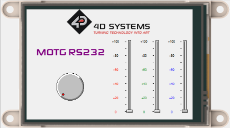
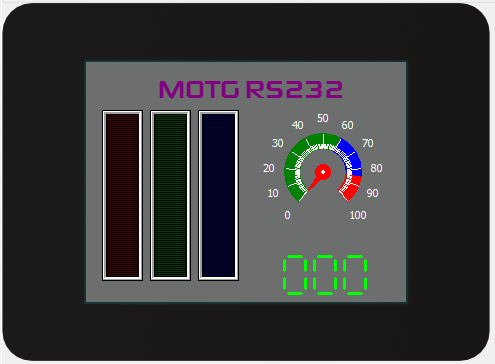
This project uses MOTG RS232 as communication interface between two gen4 display modules. The device 1 is gen4-uLCD-35DT as controller, and device 2 is gen4-uLCD-32D-CLB as monitor at the same time controls RGB Led and Servo motor connected through the PWM pins.
The MOTG RS232 are attached to each devices that converts the TTL level voltage from the display to the RS232 level voltage. This RS232 level voltage can now be transmitted over a distance between the two gen4 displays.
How It Works

Components


- gen4 –uLCD-35DT
- gen4 –uLCD-32D-CLB
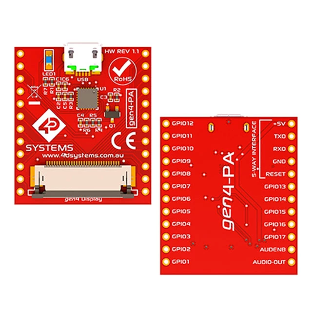
- gen4 PA
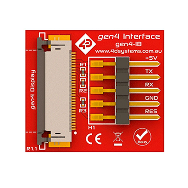
- gen4 IB
- Breadtooth
- MOTG RS232
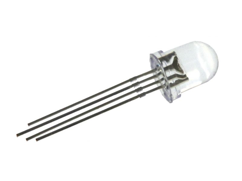
- RGB Led
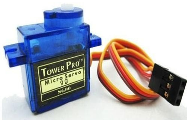
- Servo Motor
- 330 ohm resistors
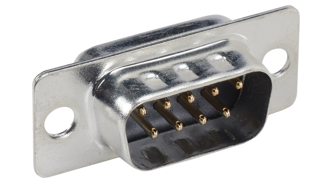
- DB9 Connector(Male)
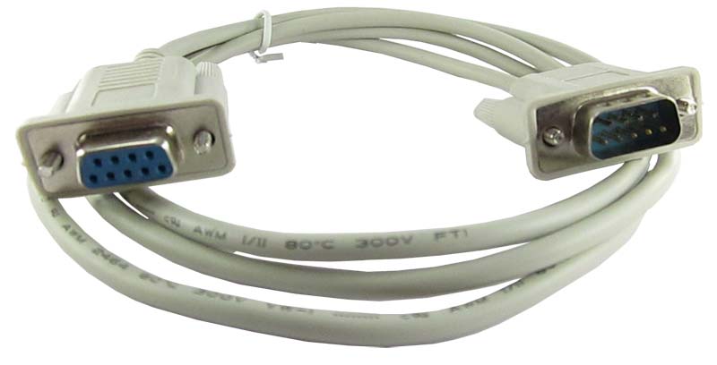
- Serial Cable (female to female)
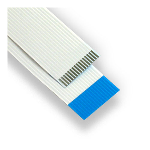
- FFC Cable
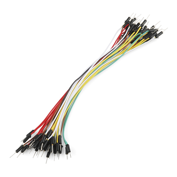
- Jumper wires
Build
Device 1
1. Connect the display and gen4-IB(Interface Board) using FFC cable.
2. Put the Breadtooth to the breadboard.
3. Using jumper wires, connect the Rx and Tx of the gen4-IB to the Rx and Tx of the Breadtooth, respectively.
4. Solder a wire to the DB9 male connector pin 2, pin 3, and pin 5. Connect the wire to the MOTG RS232, pin2 to the Tx, pin 3 to the Rx, and pin 5 to the GND.
5. Slide the MOTG RS232 to the Breadtooth.
6. Connect Serial cable to the DB9 connector.
Device 2
1. Connect the display and gen4-PA using FFC Cable
2. Put the Breadtooth on the breadboard.
3. Using jumper wires, connect the Rx and Tx of the gen4-IB to the Rx and Tx of the Breadtooth, respectively.
4. Solder a wire to the DB9 male connector pin 2, pin 3, and pin 5. Connect the wire to the MOTG RS232, pin 2 to the Rx, pin 3 to the Tx, and pin 5 to the GND.
5. Slide the MOTG RS232 to the Breadtooth.
6. Connect Serial cable to the DB9 connector.
Program


Download the project file here.
Device 1
TrackBar1 – for changing the red colour of the led. (1st image)
TrackBar2 – for changing the green color of the led (2nd image)
TrackBar3 – for changing the blue color of the led (3rd image)
To be able to use the knob you need to include the XYposToDegree library (4th image)
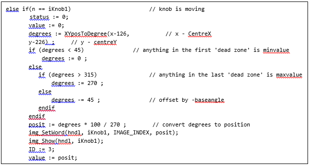
Knob – for changing the angle of the servo motor. (5th image)
Sending data to the Serial (6th image)
Device 2
Define constant (7th image)
Use COM1 (8th image)
Main (9th image)
If the device 2 received the qualifier which is ‘@’,
the two device will now sync and if the buf is greater than 2, it will start capturing data and put it to ID, val and chk.
Click on the “Build Copy/Load” button.
Note: This step could be skipped. However, compiling is essential for debugging purposes.
Connect the display to the PC using uUSB-PA5 and a mini USB cable. Make sure that you are connected to the right port. Red Button indicates that the device is not connected, Blue Button indicates that the device is connected to the right port.
Now click on the “(Build) Copy/Load” button.
Demonstration