LIDAR PointCloud: 3D Mapping With Stepper Motor Control and Visualizer
by Dtucker78 in Circuits > Lasers
14690 Views, 134 Favorites, 0 Comments
LIDAR PointCloud: 3D Mapping With Stepper Motor Control and Visualizer


Project Overview
This project integrates a 2D LIDAR sensor and a stepper motor to create a system capable of scanning and visualizing 3D spatial data. The scanning process captures distance and angle measurements as the motor rotates the LIDAR sensor through a semi-circular range (180°). The collected data is filtered for quality, tagged with rotational angles, and saved in a CSV file for further processing. The system is robust, with built-in error handling to ensure safe shutdown of the motor and LIDAR in case of interruptions. Users can customize the scanning process, such as adjusting the number of scans per step, to suit various applications.
Data Processing and Visualization
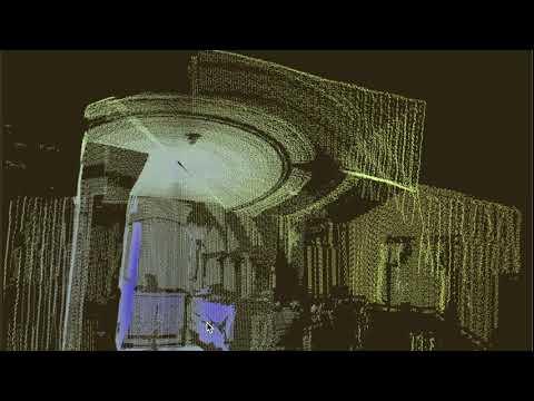
Once the data is collected, a secondary script processes the CSV file to generate a 3D point cloud in Cartesian coordinates. This data is stored in a .ply file and visualized interactively using Open3D. The visualization includes features like:
- Color-coding based on distance
- Point smoothing
- Adjustable rendering options
A user-friendly GUI built with Tkinter allows users to:
- Select CSV files
- Monitor progress
- Visualize the results with ease
Applications
This system is ideal for applications in:
- Robotics
- Spatial analysis
- Educational demonstrations
It offers an accessible yet powerful tool for exploring and understanding 3D environments.
Supplies
- Sturdy Tripod - https://a.co/d/2sOvIEC
- Nema 17 Stepper Motor Bipolar 2A - https://a.co/d/fs6d2Pl
- Stepper Motor Controller Tic T825 - https://www.pololu.com/product/3130
- Slamtec RPLIDAR A1 360 Laser Range Scanner - https://www.adafruit.com/product/4010
- 24V DC Power Supply Adapter 24Volt 2A 48W - https://a.co/d/7g2KmHz
- Access To A 3D Printer
- Four M2.5 Bolts - https://a.co/d/5B4wBcS
- Eight M2.5 Washers - https://a.co/d/5B4wBcS
- DC Power Female Pigtail Connectors 2.1 x 5.5mm - https://a.co/d/0j79Xo2
- Super Glue - https://a.co/d/9rMa1fW
3D Printing
The first step in this project is to 3D print the LIDAR mount and stepper motor to tripod adapter. Attached to this step are the STL files to print. These were created in OpenSCAD.
If you need to modify the 3D prints, here is the code that created the STL files:
Only print LIDARMount.stl and StepperTripodMount.stl You do not need to print RPLIDAR.stl it is included here if you want to use OpenScad and make changes. It is required for LIDARMount.scad
Assembly & Set Up


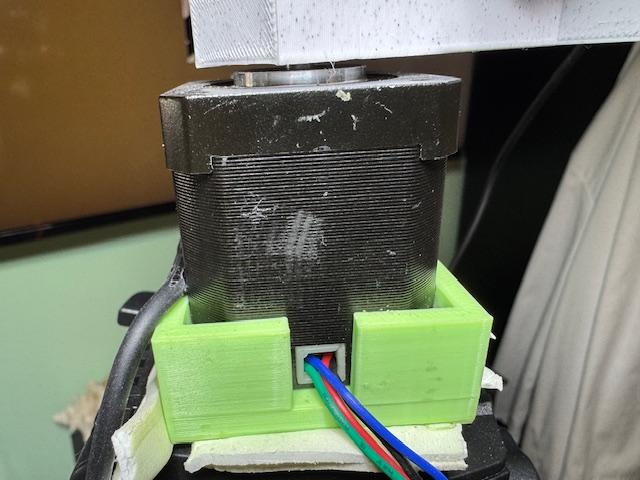
Install the Stepper Motor: Gently press the stepper motor into the StepperTripodAdapter.scad print. Ensure it fits securely. Pay close attention to the motor's orientation, positioning it so the wires route through the cutout on one side of the print.
Set Up the Tripod: Place the tripod on a stable surface. Secure the stepper motor to the tripod by attaching it to the camera mount located at the bottom of the StepperTripodAdapter.
Attach the Lidar Mount: Use four M2.5 bolts to secure the LidarMount to the RPLIDAR A1 module. Be sure to use eight washers—one for each bolt. For each bolt, place a washer first, then pass the bolt through the 3D-printed mount, add another washer, and finally insert the bolt into the RPLIDAR module’s leg. Ensure proper orientation, so the module sits over the long bar extending from the mount.
Press the Lidar Mount onto the Stepper Motor: Firmly press the LidarMount onto the stepper motor shaft using the hole in the long bar. Make sure it fits snugly without obstructing the lidar module. The mount should not bottom out against the stepper motor body. This is a press-fit, but a small dab of super glue on the shaft can help secure it.
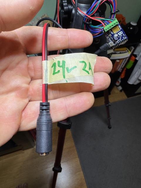
Wire the T825 Stepper Motor Controller: Connect both the power and the stepper motor to the T825 stepper motor controller. Power connections can be made in any manner you prefer. I used a barrel-type DC power female pigtail connector for easy plug/unplug of the DC power supply. For the motor wiring, follow the instructions here: Pololu Motor Wiring Instructions.
Download Controller Software: Download the appropriate T825 stepper motor controller software for your system from the following link: Pololu T825 Resources.
Install Python: Install Python for your system from Python Downloads.
Install Open3D: Install Open3D for your system by following the instructions here: Open3D Getting Started.
Install the RPLIDAR Module: Install the Python module for RPLidar A1 and A2 rangefinder scanners using this link: RPLidar Python Module.
Testing
With everything assembled and the required software installed, you're ready to begin testing your setup.
Testing Steps:
- Test the stepper motor connection: Open the Pololu Tic Stepper Motor Controller software you downloaded from the Pololu T825 Resources page. Connect the controller to power and then plug the USB cable from the controller into your computer. The software should detect your controller, and the interface will activate.
- You can adjust settings and use the "Set Position" slider to test motor movement. If the controller isn’t detected or the motor doesn’t move, refer to the troubleshooting documentation at Pololu Troubleshooting Guide.
- Test the RPLIDAR A1 module: Connect the RPLIDAR A1 to your computer using a separate USB port. When properly connected, the module will spin on its vertical axis, indicating it's powered and ready. Next, create a Python script to test the module. Save the following code as rplidarTest.py:
- Open a command prompt and navigate to the directory where you saved rplidarTest.py. Run the script using the command:
- If the module starts spinning and streams data to the command window without errors, your RPLIDAR is working correctly. If errors occur, verify the PORT_NAME variable matches your system’s port name:
- To find the correct port name:
- macOS/Linux: Run ls /dev/tty.* in the terminal.
- Windows: Use the Device Manager or run mode in the command prompt.
- Update the PORT_NAME variable in the script accordingly.
- Next Steps: Once the tests are successful, you're ready to set up the directory structure and organize your Python files. Proceed to the next step in the tutorial for details.
Python Code
Attached to this step are the 2 Python files for this project:
Scanning Script (Scan.py):
- Motor Control: Uses ticcmd to set up and rotate the motor in small steps (1/4 microstepping) to scan 180°.
- LIDAR Data Collection: Captures distance and angle measurements, filters valid readings, and tags them with rotational data.
- Data Storage: Saves the processed data in a timestamped CSV file under the ./CSV directory.
- Error Handling: Includes safe shutdown procedures for the LIDAR and motor in case of interruptions.
Visualization Script (convertAdjust.py):
- Data Conversion: Converts polar coordinates (angle, distance) and rotation into 3D Cartesian coordinates.
- Styling: Adds color-coding based on distance for visual clarity.
- PLY File Generation: Saves the 3D data as a .ply file in the ./PLY directory. Supports integration with other 3D processing tools.
- Visualization: Utilizes Open3D to display and interact with the point cloud. Features adjustable background colors and point smoothing using voxel downsampling.
- Graphical User Interface (GUI): Built with Tkinter to simplify file selection and provide status logs. Users can load CSV files and visualize the data in 3D with a few clicks.
Workflow:
- Scanning Phase: Run the first script to collect and save spatial data from the environment.
- Visualization Phase: Use the GUI in the second script to load the CSV data, process it into a 3D model, and interactively visualize the results.
Directory Structure:
Your project directory should be set up something like this. You will need to create a CSV and PLY directory next to the scan.py and convertAdjust.py files. These will hold the files create during scanning and processing. The csv and ply files are just examples for what it should look like after you have run a few scans.
○ CSV
├── Garage_20241118_151324.csv
├── Kitchen_20241114_073514.csv
├── LivingRoom_20240912_063249.csv
└── Office_20241203_152838.csv
○ PLY
├── Garage_20241118_151324.ply
├── Kitchen_20241114_073514.ply
├── LivingRoom_20240912_063249.ply
└── Office_20241203_152838.ply
○ convertAdjust.py
○ scan.py
Note: Be sure to update the LIDAR setup value in your scan.py script to match the PORT_NAME from your test above.
Locate the following line in scan.py:
Replace /dev/tty.usbserial-0001 with the port name you identified during testing. This ensures your script connects to the correct port for the RPLIDAR module.
Run a Scan

Now that your tests are successful and your folder structure is set up with the necessary Python files, you're ready to start scanning!
Steps to Begin Scanning:
- Open a command prompt and navigate to the directory where you set up this project.
- Run the scan by typing the following command:
- You should hear the motor engage and see data streaming from the RPLIDAR A1 module. The motor will step horizontally every few seconds, scanning until it completes a 180° arc. Once finished, the script will automatically exit back to the command prompt.
- If you encounter any errors, refer to the previous testing steps to troubleshoot potential issues.
Verify the Scan Data:
- Navigate to the CSV directory in your project folder.
- Look for a file with a name similar to scanData_20240905_090655.csv. This file includes the date and time of the scan in its name.
- Open the CSV file to inspect the recorded data. You should see the results of the scan logged in this file.
Convert CSV to PLY and View Your Scan

Now to see the scan you made and output the PLY file. From the same directory where you ran your scan, launch the visualizer and converter using python convertAdjust.py. This will open a new window called Point Cloud Visualizer where you can select a CSV file. Click the Open CSV button at the top and select the CSV file created in the previous step. This will open another window titled Open3D. You can zoom in and rotate your scan in 3D using this window. Once done, you can close the Open3D window and select another CSV file for viewing or close the program. Once you select a CSV file and view it, the script will also save a PLY file of the data you are visualizing in the PLY directory in your project setup. You can use this PLY file in any application you want to further work with or edit the data.
Note: This has only been tested on macOS, so you might need to modify the script to get it working on your system.
Tips and Troubleshooting
Wire Routing and Tangling: Make sure your USB wires are not getting caught on anything and that the RPLIDAR mount can spin 180° with no interference on the stepper motor.
RPLIDAR Needs to Be Level on Motor Shaft: If you notice a mismatch or offset in the two halves of the scan (180° x 2 = 360), this may be caused by the RPLIDAR mount not being level on the motor shaft.
Vibration Control: If you observe excess noise in your visualizations, such as undefined edges of objects or uneven surfaces, this may be caused by vibrations in your setup. Check that there is little to no play in the mount at the top of the camera tripod. If there is, use foam or other material to secure the 3D-printed motor mount. Additionally, ensure your tripod is sturdy and not moving.
Proper USB Port for RPLIDAR: Verify that you are using the correct port by running the RPLIDAR test script mentioned above.
Where to Go From Here....
There are several ways to extend and improve the project for different applications:
- Data Processing Enhancements:
- Explore additional data processing techniques, such as noise reduction or outlier filtering, to improve the accuracy and quality of the 3D point cloud data.
- Implement more advanced algorithms for 3D reconstruction or mapping, such as SLAM (Simultaneous Localization and Mapping) to make the system capable of more complex tasks.
- Hardware Improvements:
- Experiment with different LIDAR sensors or stepper motors to see how changes in hardware affect the system’s performance.
- Upgrade the tripod or mounting setup to allow for better stability and more precise scanning.
- GUI Enhancements:
- Customize the Tkinter GUI by adding features like real-time monitoring of the motor’s progress, interactive point cloud adjustments, or advanced export options for the data.
- Adding additional functionality, such as the ability to export the data in different formats (e.g., XYZ, PCD, or LAS) or integrate with other software tools.
- Automation and Scripting:
- Automate the scanning process by writing scripts to control scanning intervals, angles, and other parameters based on user input or environmental conditions.
- Set up batch processing to automatically scan multiple areas or objects, saving time and improving efficiency.
Additional Videos


