LOGO Emulator Using AVR


Forty years ago, researchers developed a programming language that would become a brilliant educational tool. Logo was an interesting Programming Language, designed by Seymour Papert for children, once much used in schools, but never fully appreciated. Logo was about manipulating a triangle on the screen (a dot in my project) that can leave a mark behind it, with the intention of drawing pictures. Logo is rarely used these days in today’s classroom. In order to take a trip down the memory lane I have designed a machine capable of emulating some of the basic Logo commands.
Operation

Back in 80's the turtle looked like a little triangle in the middle of the screen. The head indicated the turtles direction. When the turtle moved it drew a line behind him. Using a mere 8 x 8 LED matrix for display, implementation of a triangle was not feasible. The project uses a blinking dot to represent the turtle. Some of the supported commands are given below.
Basic Supported Commands :
- FD 0-7 (Move the turtle forward 0-7 steps)
- BK 0-7 (Move the turtle forward 0-7 steps)
- RT 45/90 (Turn the turtle to the right 90º or 45º)
- LT 45/90 (Turn the turtle to the right 90º or 45º)
- PU (Pick the turtle's pen up off the display)
- PD (Put the turtle's pen back down on display)
- CS (Clear the screen and start over)
- HT (Hide the turtle)
- ST (Show the turtle)
Design

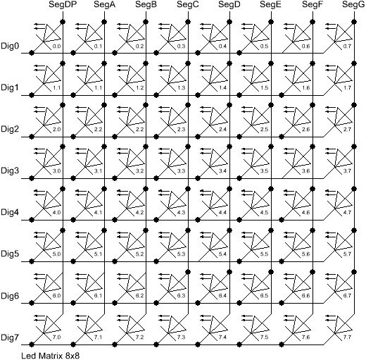
The project uses an 8x8 LED matrix to display the player’s move.The LED matrix is controlled by a display driver from Maxim Integrated- MAX7219. The MAX7219 are compact, serial input/output common-cathode display drivers that interface microprocessors (µPs) to LED Matrix.The MAX7219 takes care of all the multiplexing, decoding and refresh circuitry.
MAX7219 is controlled by a ledcontrol library. The library provides a basic set of functions by which either individual or groups of LED's can be switched on and off. Below is a code snippet which is used in the project to address individual LED's:
//switch on the led in the 3'rd row 8'th column
//and remember that indices start at 0!
lc.setLed(0,2,7,true);
//Led at row 0 second from left too
lc.setLed(0,0,1,true);
delay(500);
//switch the first Led off (second one stays on)
lc.setLed(0,2,7,false);
A LED Bargraph is also wired to display the turtle's orientation. For any given orientation the turtle can either move forward or backward. 8 different orientation are possible namely: N , NE , E , SE , S , SW , W , NW , N.
Input is taken via a normal PS/2 keyboard. The CLK and Data pins of PS/2 keyboard are connected to pin 5 & pin 6 of Atmega328 respectively.Command input size is restricted to 4 characters only.
Schematics

Code
The code is written using arduino IDE. Import all the necessary libraries before compiling and uploading the code. Follow the instruction here to import the libraries.
Pictures & Video


