LYME: Sending Live Video Through the Air on a Laser Beam
by daniely101 in Circuits > Electronics
209 Views, 2 Favorites, 0 Comments
LYME: Sending Live Video Through the Air on a Laser Beam
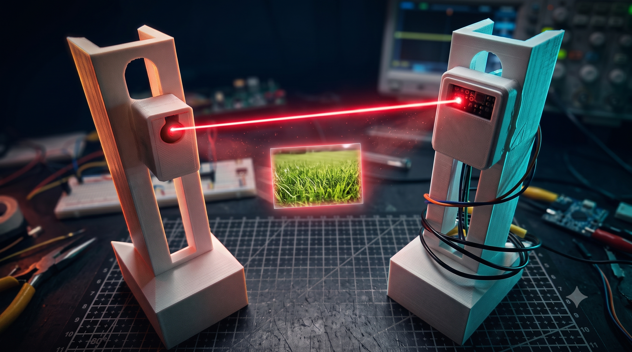
LYME is a fully custom, free-space optical (FSO) link that sends real-time analog video across open air on a laser beam: no WiFi, no digital radio, no compression. Instead of blinking the laser on and off to send bits, the laser's brightness is smoothly modulated to track a standard Composite Video (CVBS) waveform, the same analog signal old CRT TVs and CCTV cameras use.
The build uses about as little as possible on purpose: one transistor on the transmit side and one op-amp on the receive side, carrying ~5 MHz of bandwidth — enough for full-motion, full-color video, live, over a beam of light.
Carrying that much bandwidth over a raw analog circuit means you have to precisely measure what's happening across the airgap. A massive shoutout to PCBWay for sponsoring this project and sending over the oscilloscope you see on my bench. Beyond their famous circuit board manufacturing, PCBWay also has a massive store full of test equipment and tools for creators. Check them out: pcbway
I deliberately picked the hardest payload I could think of. Sending text over a laser is easy and proves almost nothing. Video pushes cheap analog hardware to its actual limit — and getting it to lock into a clean, stable picture on a monitor is genuinely satisfying to watch happen.
LINK FOR GITHUB: LINK
Supplies
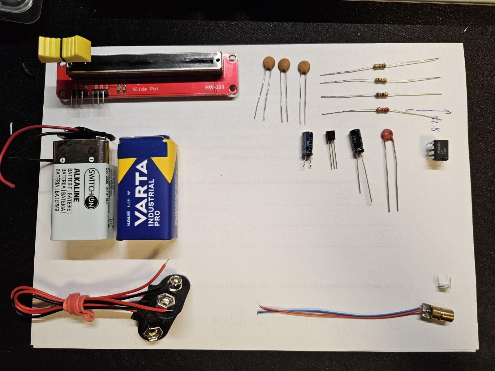
Video source (pick one)
- ESP32 dev board (for generating test patterns — easiest first test)
- Raspberry Pi (any model with a composite/TV-out RCA port) + Raspberry Pi camera or USB webcam — for live video
- Raspberry Pi OS Buster/Legacy image (newer Bullseye/Bookworm breaks the analog TV-out) or an esp32
Transmitter (TX)
- 1× Red laser diode module
- 1× 2N2222 NPN transistor
- 1× 10 kΩ potentiometer — DC bias / brightness
- 1× 1 kΩ resistor — base series resistor
- 1× 100 Ω resistor — laser current limit
- 1× 47 µF electrolytic capacitor — AC coupling (low freq)
- 1× 100 nF ceramic capacitor — AC coupling (high freq)
Receiver (RX)
- 1× BPW34 PIN photodiode — not a solar cell
- 1× LM318N high-speed op-amp — do not substitute LM358/TL072
- 1× 2.2 kΩ resistor — transimpedance gain
- 1× 8.2 pF capacitor — feedback compensation, critical for stability
- 1× 100 µF electrolytic capacitor — output AC coupling
- 1× 75 Ω resistor — series impedance terminator (fixes capture-card smearing)
- 2× 100 nF capacitors — supply decoupling
- 2× 9 V batteries + clips — true ±9 V dual rail supply
Capture / display
- USB capture card (e.g. EasyCap) or any TV/monitor with a native RCA composite input
- RCA cables
Enclosure
- 3D printer + filament (STL files: `base.stl`, `boxTX.stl`/`lidTX.stl`, `boxRX.stl`/`lidRX.stl`) NOT necessarily
Tools
- Breadboard or perfboard
- Soldering iron
- Oscilloscope (very helpful for calibration, not strictly required)
- Multimeter
How It Works: Why Analog Video, Not Digital Bits
Before building anything, it's worth knowing why this project is analog end-to-end — the two "obvious" digital approaches both fail:
- Raw digital bits: an uncompressed 640×480 grayscale frame is ~307,200 bytes (~2.45 Mbit) *per frame*. A basic microcontroller-and-transistor optical link topping out around 1 Mbps delivers under 0.5 FPS. Forcing 15 FPS shrinks resolution to a useless ~32×32 pixels.
- Still images over audio tones: robust against interference, but encoding and sending one image takes 8–120 seconds. Not remotely "live."
The fix is to go back to an analog broadcast standard: Composite Video (CVBS). A single ~5 MHz analog waveform carries sync pulses, brightness, and color all at once. Instead of switching bits, the laser's intensity is amplitude-modulated to track that waveform directly — sidestepping digital bandwidth limits entirely and giving smooth 50/60 FPS video.
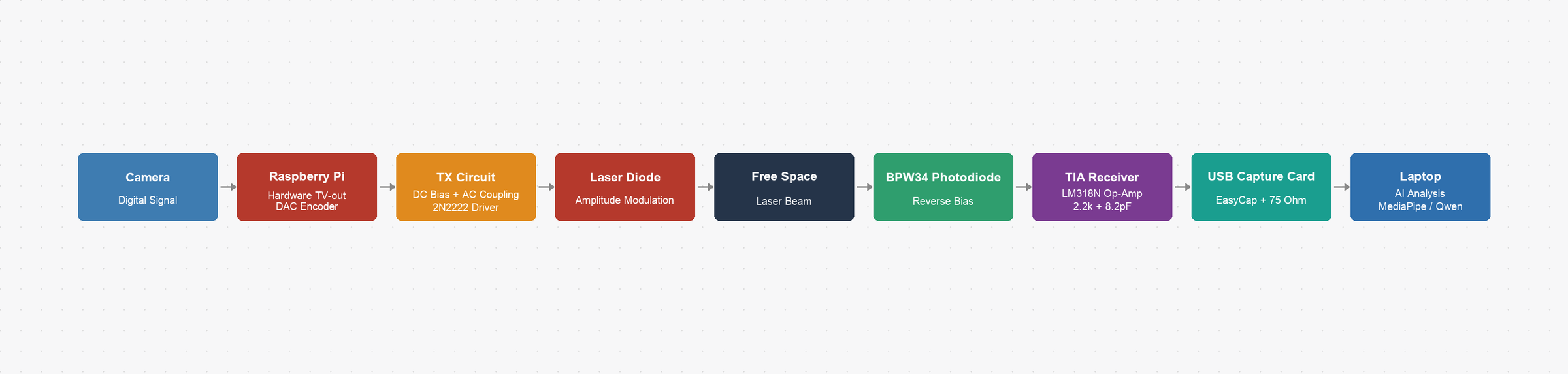
The full signal path:
1. Camera → Raspberry Pi (digital video in) / or esp32
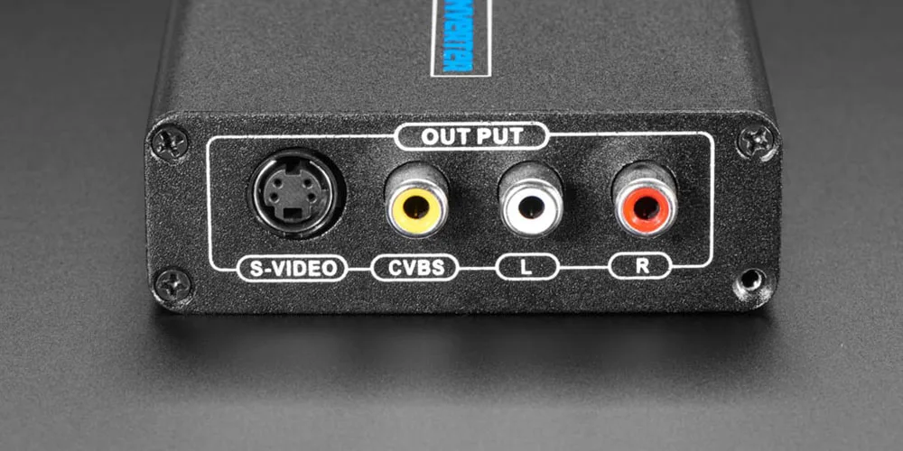
2. Pi's hardware TV-out → analog CVBS signal
3. Transmitter circuit → mixes CVBS onto a DC bias, drives the laser
4. Laser beam crosses open air
5. BPW34 photodiode (reverse-biased) → tiny photocurrent
6. Receiver TIA → converts photocurrent back to a video voltage
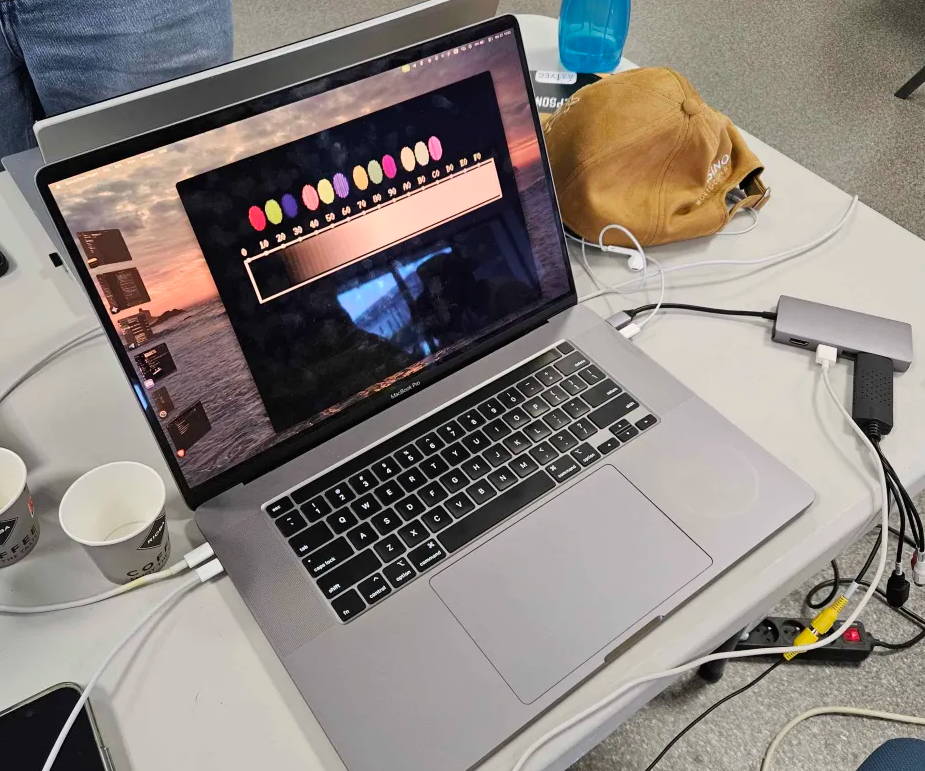
7. USB capture card / RCA display → picture
Generate a Test Signal With an ESP32
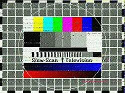
Before wiring up a live camera, prove the laser link itself works using an ESP32's built-in 8-bit DAC.
1. Flash the ESP32 with code that generates an NTSC test pattern.
2. Output the analog waveform directly from GPIO26/25.
3. Use this clean, repeatable test signal to calibrate the transmitter and receiver before adding the complexity of a live camera feed.
This step is optional if you're confident in your circuit, but it isolates variables and saves debugging time later.
Set Up the Raspberry Pi As the Live Video Source
1. Flash Raspberry Pi OS Buster (Legacy) — not a newer release. Newer versions use a Wayland/Mutter graphics stack that conflicts with direct access to the analog composite output.
2. Connect a camera (Pi Camera or USB webcam) to the Pi.
3. Do not connect an HDMI monitor — plugging one in disables the analog composite (yellow RCA) port. Control the Pi headlessly instead:
```
ssh pi@raspberrypi.local
```
4. Start the video stream directly to the framebuffer:
```
sudo ffmpeg -f v4l2 -video_size 640x480 -i /dev/video0 -pix_fmt rgb565le -f fbdev /dev/fb0
```
5. The Pi's hardware TV-out encoder converts this into a standard analog PAL/NTSC CVBS signal, available on the yellow RCA port.
Build the Transmitter
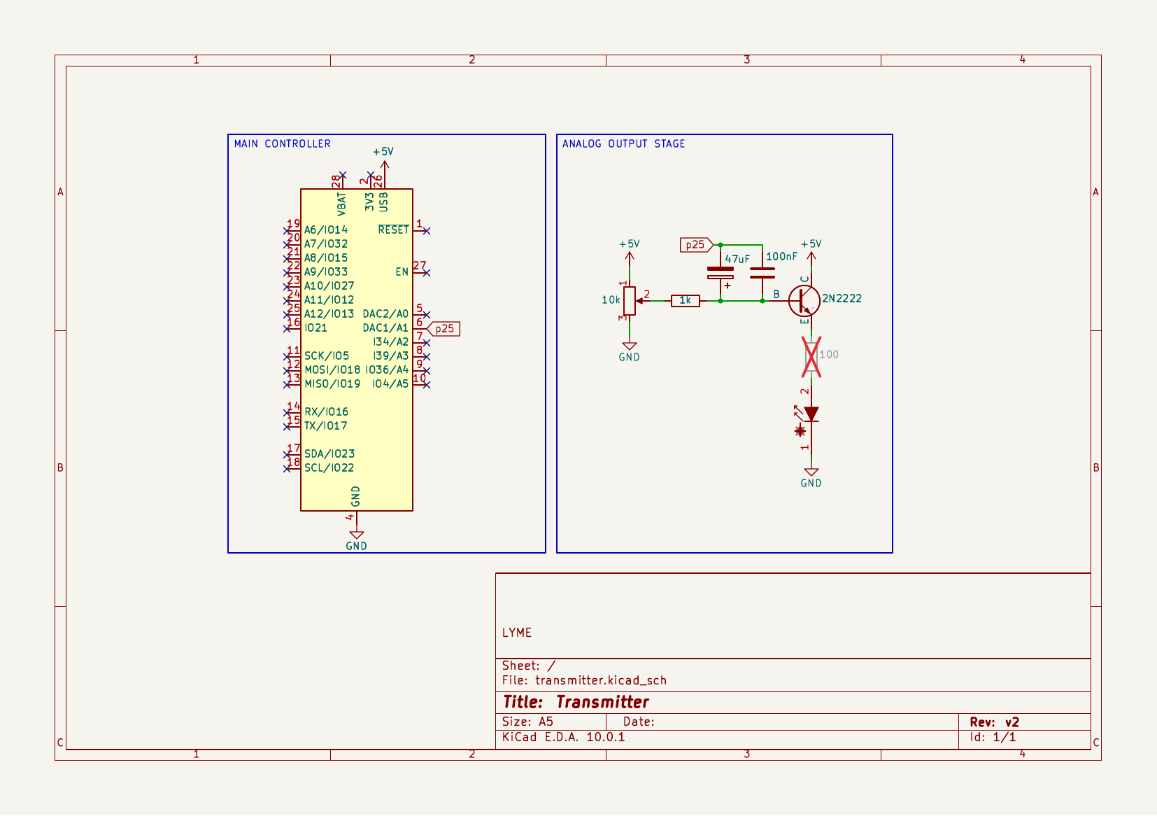
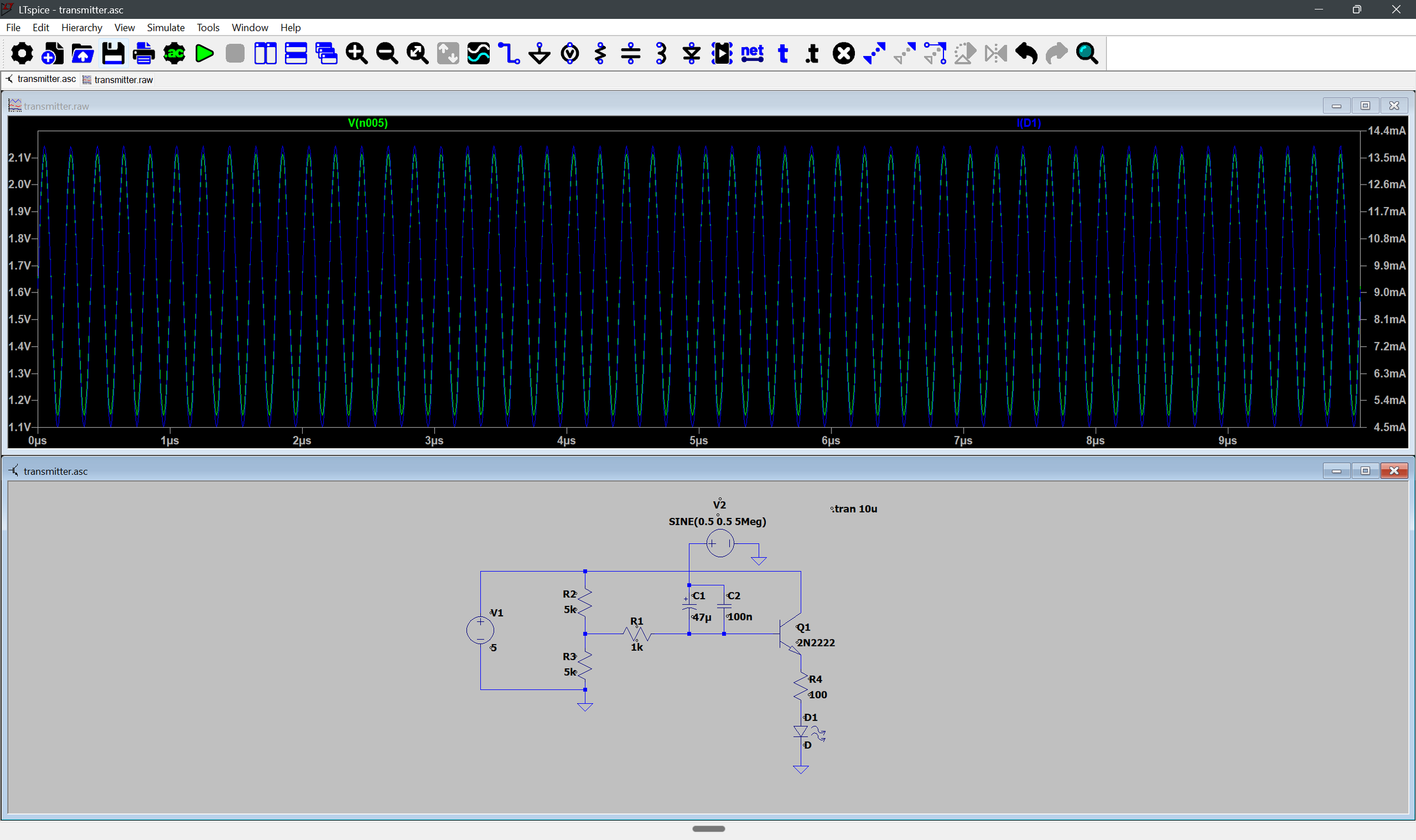
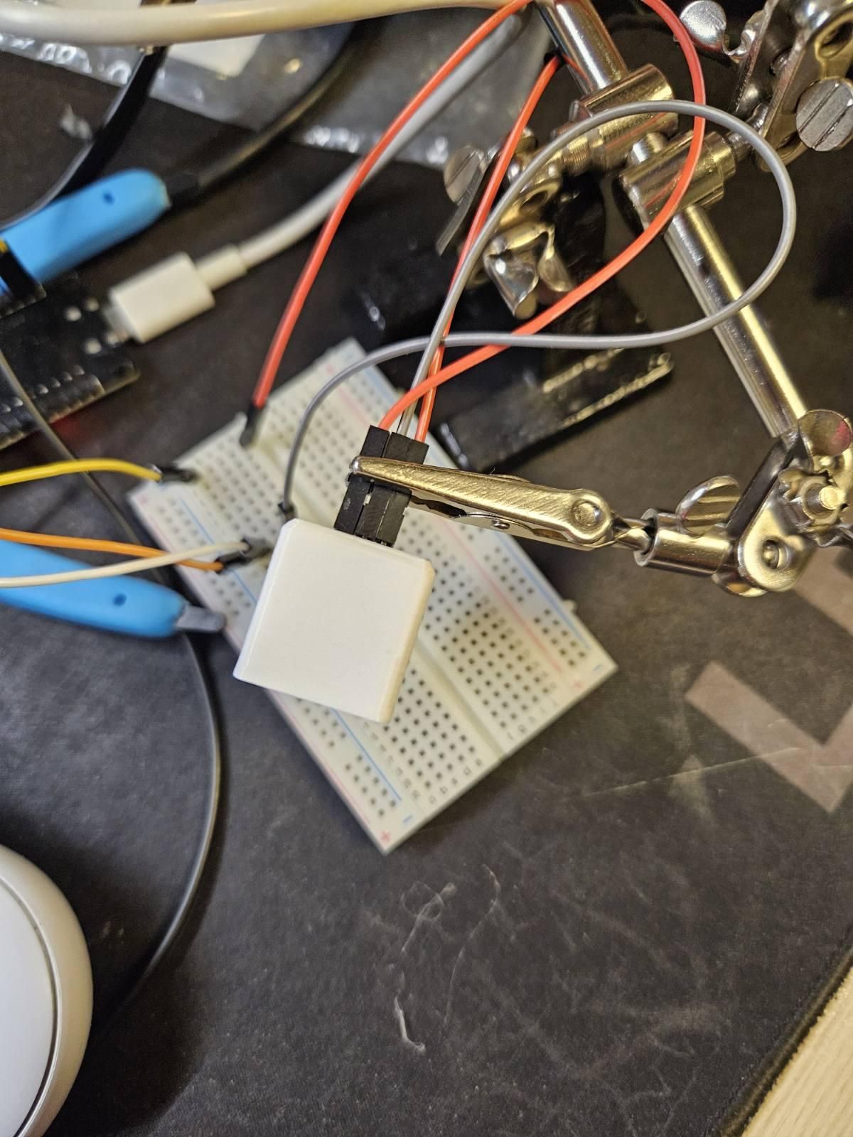
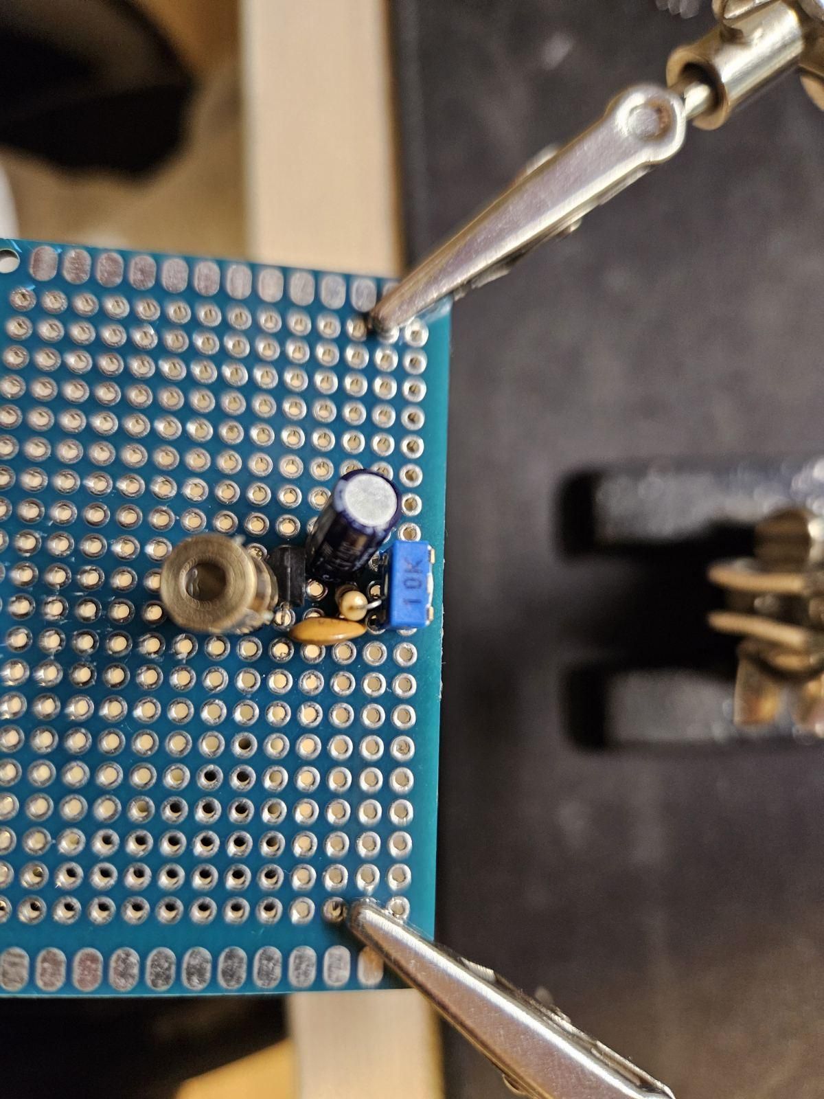
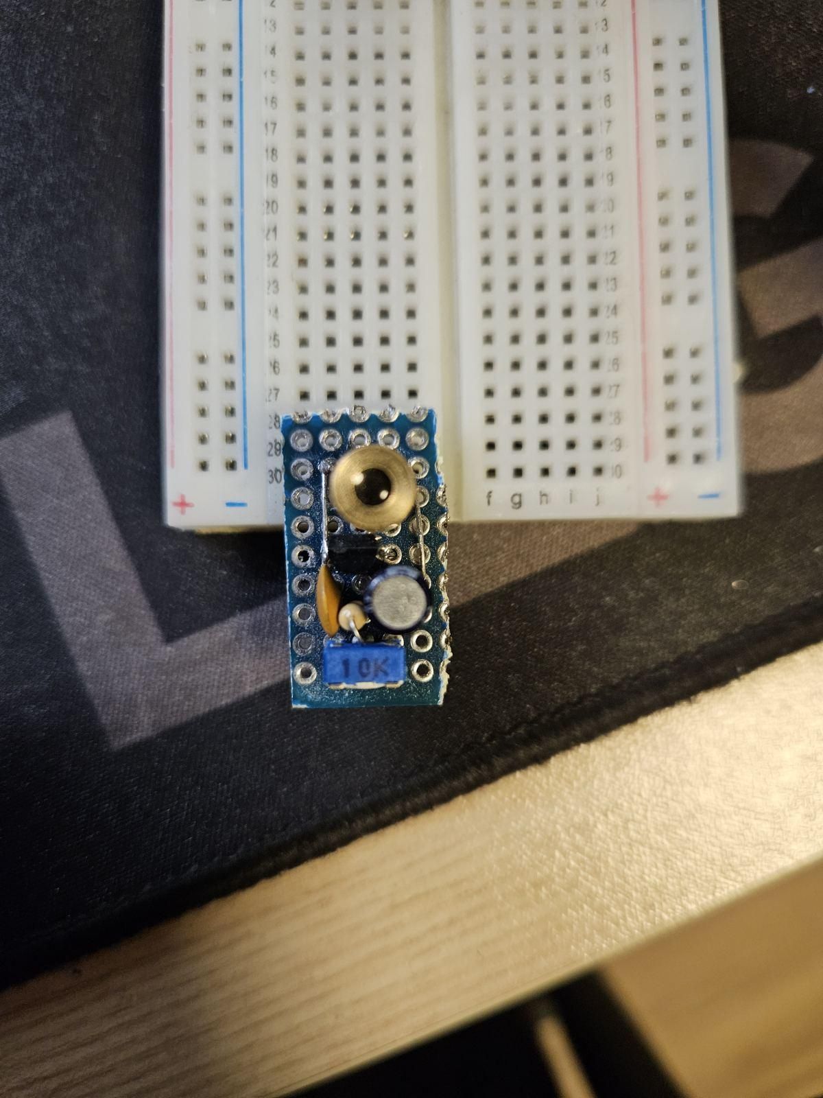
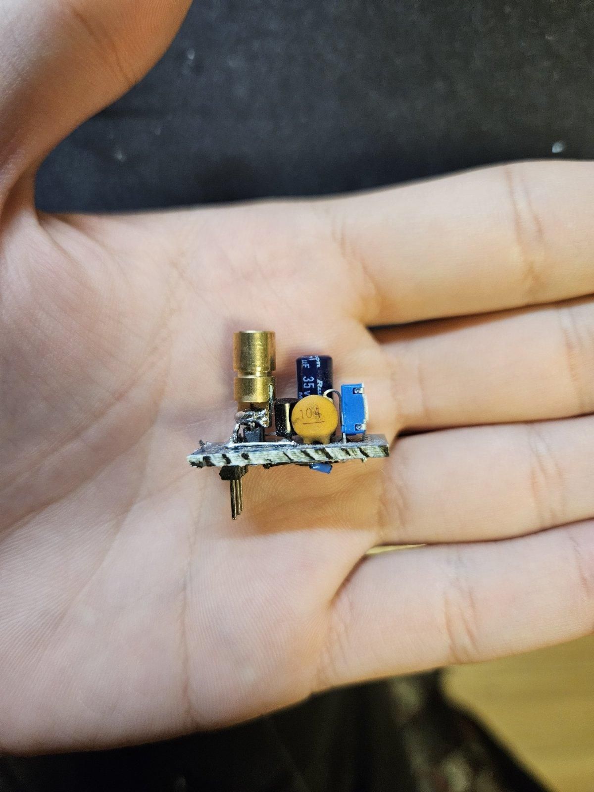
A laser diode won't respond to a raw ~1 Vpp video signal — it needs a DC bias of 2.5–3.0 V just to start emitting, plus ~20–30 mA of current, both well beyond what a video output can supply directly. So the circuit builds this up in stages, starting with bias:
stage1:
1. Wire the 10 kΩ potentiometer (RV1) between +5 V and GND as a voltage divider.
2. Feed the wiper through a 1 kΩ resistor into the base of Q1 (2N2222).
3. This holds the laser at a steady average "carrier" brightness (its Q-point) that you can fine-tune later.
stage2:
The AC video signal has to ride on top of that DC bias without shorting it out.
1. Feed your composite video signal through two capacitors in parallel: a 47 µF electrolytic and a 100 nF ceramic.
2. Why two? The 47 µF electrolytic passes low frequencies cleanly (e.g. the 50 Hz V-sync pulses) but has too much parasitic inductance for high frequencies. The 100 nF ceramic reacts instantly to the MHz-range picture detail. Together they cover the full CVBS spectrum.
3. The junction where these capacitors meet the DC bias divider is the magic node — this is where the AC picture signal and DC carrier level combine.
stage3:
1. Feed the magic node into the base of 2N2222, wired as a common-collector (emitter follower).
2. Connect Q1's collector to +5 V and its emitter to the laser diode (through a 100 Ω current-limit resistor).
3. This stage doesn't amplify voltage — the emitter just follows the base minus ~0.7 V — but it dramatically boosts current, pulling the amps the laser needs straight from the +5 V rail without loading down the Pi's video output.
4. Power up, and adjust RV1 until the laser glows steadily — that's your carrier level.
Build the Receiver
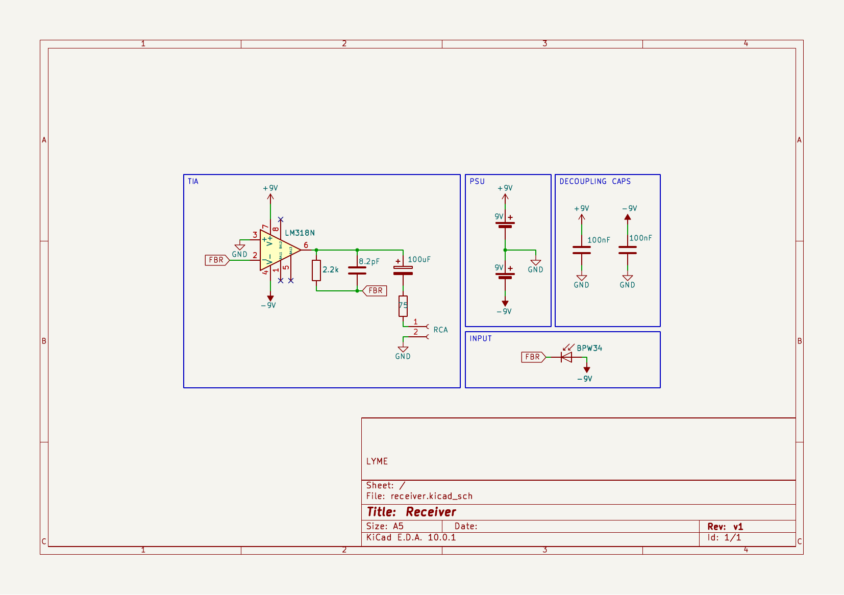
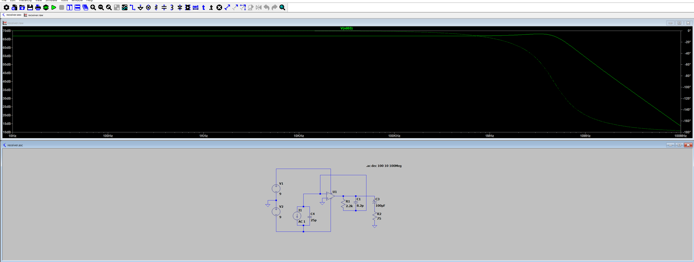
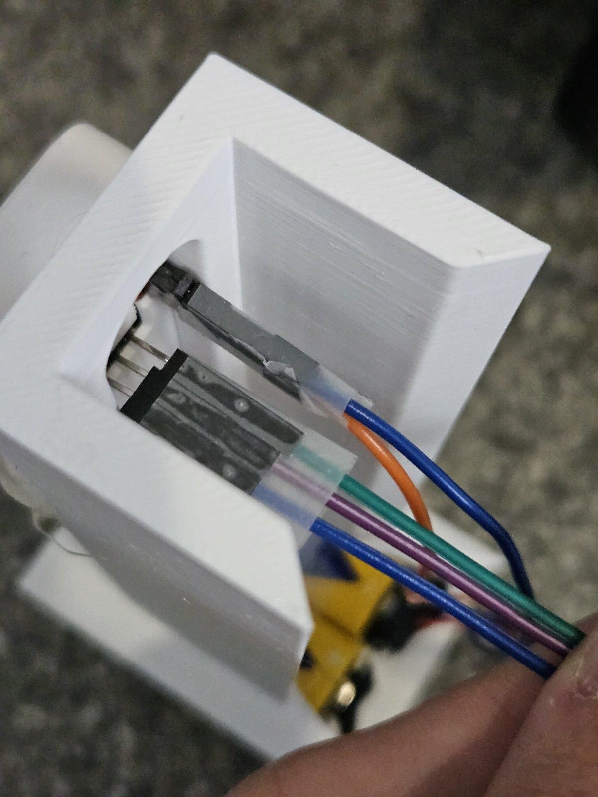
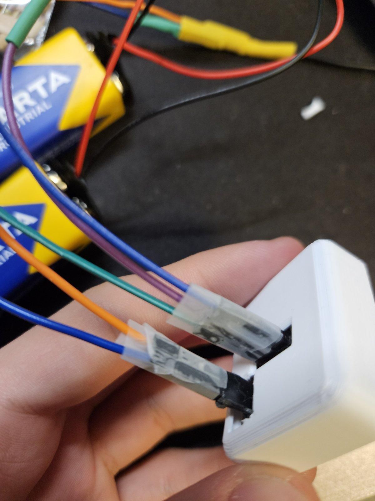
stage1:
1. Use a BPW34 PIN photodiode — not a solar panel. Solar cells have a huge junction area and microfarad-scale parasitic capacitance, which acts as a low-pass filter and limits response to tens of Hz. Useless for a 5 MHz signal.
2. Wire the BPW34 in reverse bias: anode to −9 V, cathode to the amplifier's virtual ground. Reverse bias shrinks the junction capacitance and speeds the diode up enough to track the video signal.
stage2:
The photodiode only outputs a tiny current (nA–µA range) — the TIA converts that into a usable video voltage.
1. Build the TIA around an LM318N op-amp. Don't substitute a general-purpose audio op-amp like the LM358 or TL072 — their gain-bandwidth product and slew rate are far too low and will smear the video.
2. Power the op-amp from a true dual supply: two 9 V batteries wired for +9 V / GND / −9 V, so the AC video output can swing symmetrically without clipping.
3. In the feedback path between output (pin 6) and the inverting input (pin 2), place:
- Rf = 2.2 kΩ — sets the current-to-voltage gain (Vout = −Iphoto × Rf).
- Cf = 8.2 pF — this is the critical part. The op-amp's and photodiode's combined capacitance creates instability (ringing) without it; 8.2 pF introduces a compensating zero and keeps the amplifier's phase margin above 45°.
At this point, point the laser at the photodiode and check the receiver output on a scope or a TV with a native RCA input — you should see a recognizable, if noisy, video waveform.
Fix Capture-Card Artifacts
1. Cause of the smearing: the LM318N's very low output impedance slams the signal into the RCA cable at full strength. Part of that energy reflects back down the cable when it hits the capture card's input impedance mismatch, creating an echo that smears the image.
- Fix: add a 75 Ω resistor in series at the output, right after the 100 µF AC-coupling capacitor and before the RCA center pin. This absorbs the reflections.
2. Cause of the diagonal tearing: the recovered signal's voltage is too high for the capture card's strict sync-slicer chip, which needs the H-sync pulses to sit at the lowest voltage in the signal.
- Fix: go back to the 10 kΩ potentiometer on the transmitter and carefully turn it down, lowering the laser's DC bias (and therefore the recovered signal's overall amplitude) until it falls inside the capture card's expected window. The tearing should vanish and the picture should lock into a stable 50/60 FPS stream.
3D Print and Assemble the Enclosures
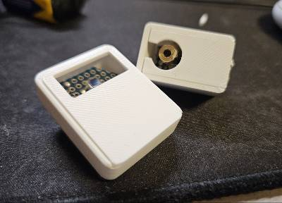
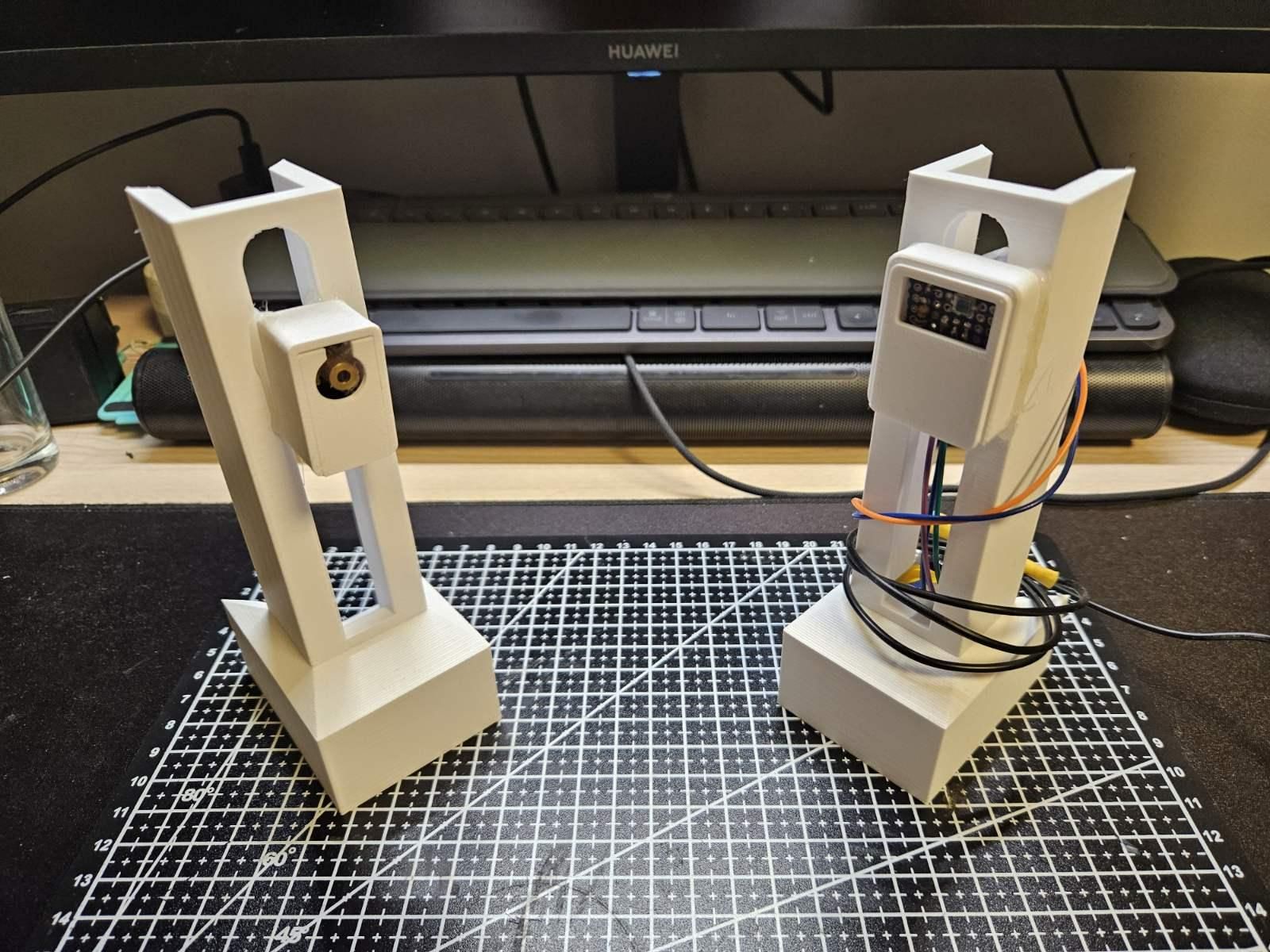
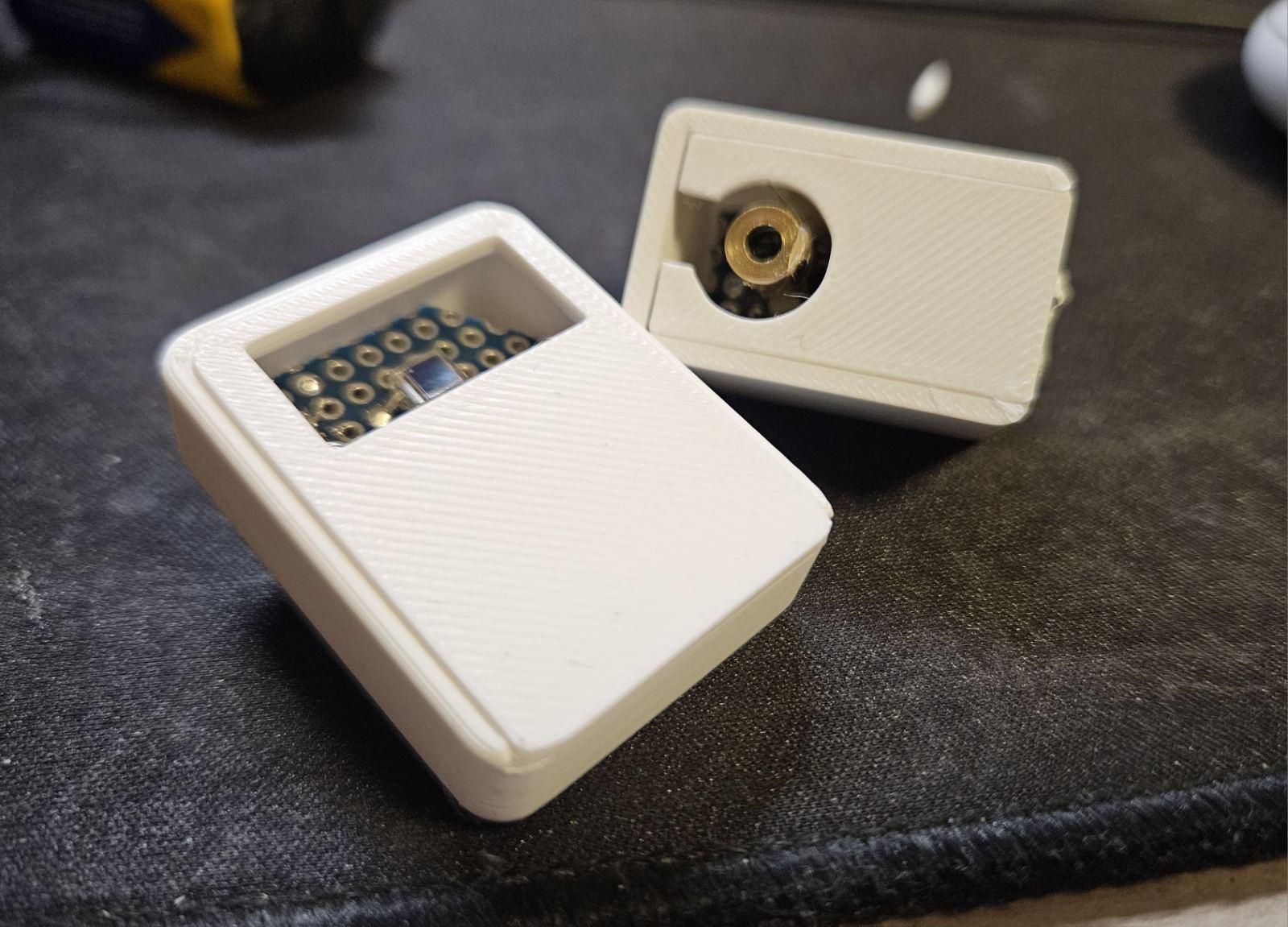
1. Print `base.stl`, plus `boxTX.stl` / `lidTX.stl` for the transmitter and `boxRX.stl` / `lidRX.stl` for the receiver.
2. Mount the TX board and laser diode in the TX box, aligned so the beam exits cleanly through the front.
3. Mount the RX board and photodiode in the RX box, with the BPW34 facing the same direction as the incoming beam.
4. Secure both onto the base for consistent alignment during testing.
Align, Power Up, and Watch It Work
1. Place the TX and RX enclosures facing each other, a few feet apart to start.
2. Power the transmitter (+5 V) and receiver (±9 V batteries).
3. Start your video source (ESP32 test pattern or the Raspberry Pi ffmpeg command from Step 3).
4. Connect the receiver's output to your capture card or RCA display.
5. Fine-tune the TX potentiometer (Step 9) until the picture locks in clean.
6. Widen the distance between TX and RX gradually and re-check alignment — free-space optical links are line-of-sight and sensitive to beam divergence.
You should now have live, real-time analog video crossing open air on a laser beam, built from a single transistor and a single op-amp.