Lady Gaga LCD TV Sunglasses
by pavithrabandara9188 in Circuits > Electronics
118 Views, 0 Favorites, 0 Comments
Lady Gaga LCD TV Sunglasses
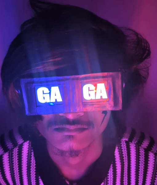
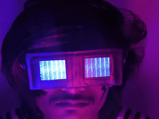
Ever wanted to turn heads the moment you walk into a room?
Inspired by the iconic, tech-infused fashion of Lady Gaga, I built a pair of custom LCD display sunglasses that can show animations, graphics, and even play short video clips right on the lenses. These aren't just sunglasses—they’re a wearable display system powered by an ESP32 and dual TFT screens.
This project combines electronics, programming, and creativity to create something truly eye-catching. Whether you're into cosplay, performance art, or just love pushing the limits of DIY tech, this build lets you wear your imagination—literally.
In this Instructable, I’ll walk you through everything: from wiring the hardware and configuring the displays to converting and uploading animations. By the end, you’ll have your own pair of programmable display glasses that look like they came straight out of a futuristic music video.
Supplies
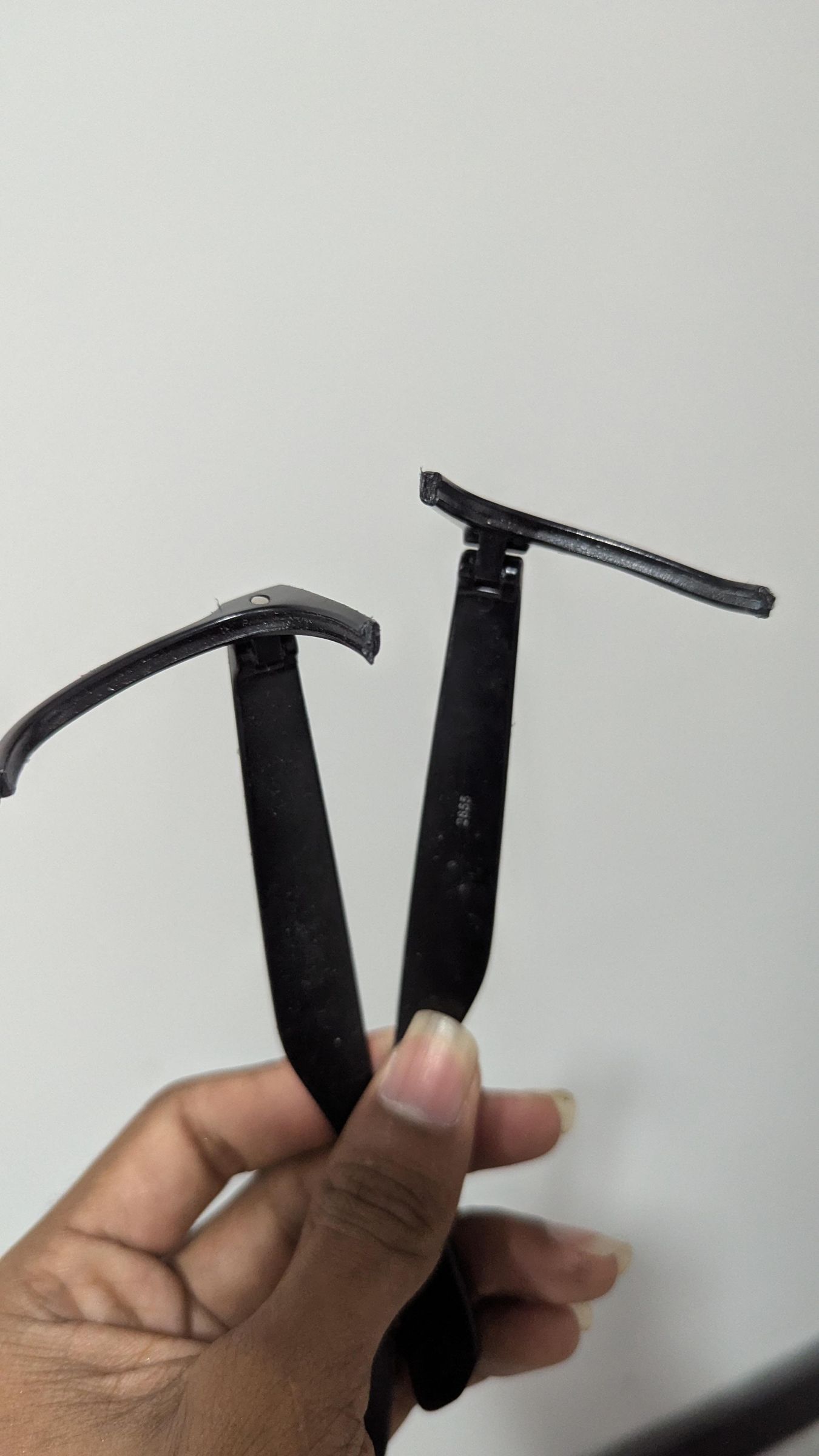
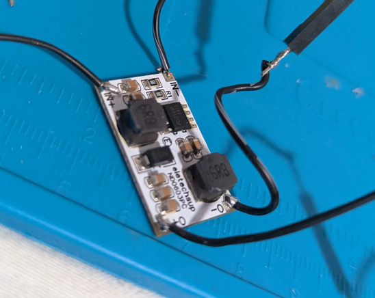
Supplies
To build these LCD display sunglasses, you’ll need a mix of electronic components, basic tools, and a few optional items depending on how polished you want the final result to be.
Electronics
- ESP32 development board (any standard version should work)
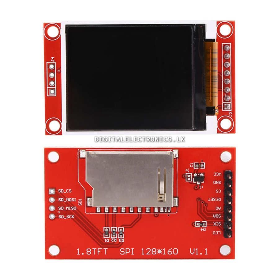
- 2 × 1.8" SPI TFT displays (ST7735, 128×160 resolution)
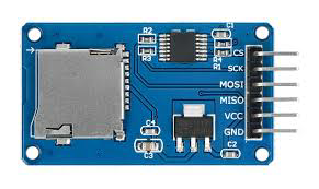
- Micro SD card module (TFT with built-in SD slot didn't work for me, so recommend using a separate module)
- Micro SD card (for storing animations/images)
- Jumper wires (male-to-male / male-to-female) - For Prototyping
- Small breadboard (for testing phase)
- Lithium-ion battery (3.7V)
- 5V Boost converter module ( When running both displays and ESP32 with the SD card module, it need more voltage than 3.3V so boost converter module is recommended if you are using Li Battery)
- TP4056 charging module (for charging battery)
️ Wearable Structure
- Old Sunglasses frame (preferably wide or flat-front style)
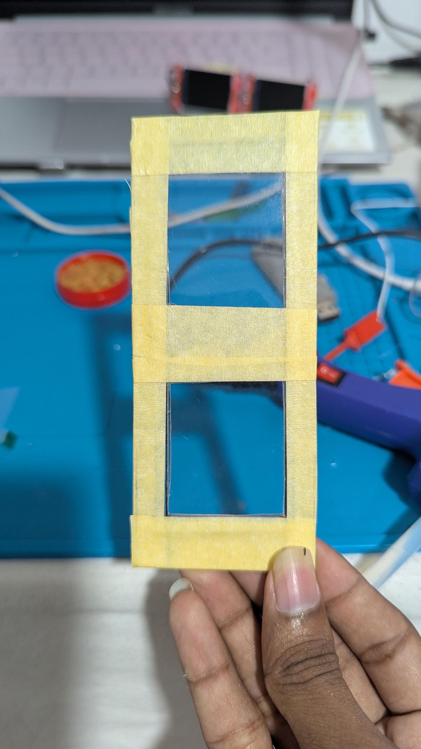
- Black acrylic sheet / plastic sheet(to mount displays)
- Foam, tape, or spacers (for positioning and comfort)
️ Tools
- Soldering iron + solder
- Hot glue gun / strong adhesive
- Wire cutter/stripper
- Small screwdriver set
- Double-sided tape
Software and Libraries
- Arduino IDE
- <AnimatedGIF.h>
- <bb_spi_lcd.h>
- <SPI.h>
- SD.h>
Optional (but recommended)
- 3D printed frame parts (for a cleaner, custom fit)
- On/off switch
- Resistors (for backlight control, if needed)
- Heat shrink tubing (for durability and neat wiring)
How It Works
This project is built around the ESP32, which acts as the main controller.
Here’s what happens behind the scenes:
- The ESP32 reads GIF files from an SD card
- Each frame is decoded using the AnimatedGIF library
- Pixel data is converted into a format the displays understand (RGB565)
- The same frame is sent to two TFT displays in parallel using SPI
The displays use the ST7735 TFT display driver, which is fast and perfect for small embedded projects.
🎬 Smooth GIF playback (not just static images)
⚡ High-speed SPI rendering (up to ~35–40 MHz)
🖥️ Dual display output (mirrored visuals)
💾 SD card storage for animations
🔋 Compact and wearable-friendly
You'll learn how to,
Wire up the ESP32, two TFT displays, and an SD card
Configure shared SPI communication correctly
Upload optimized GIF-ready code
Convert and prepare GIFs for fast playback
Tune performance for smooth animations
Mount everything into a wearable form
This project is beginner-friendly with some basic Arduino knowledge.
You should be familiar with:
- Uploading code to an ESP32
- Basic wiring (VCC, GND, GPIO)
- Installing Arduino libraries
Software Preparation


Before uploading the main code, we need to set up the Arduino environment and install the required libraries.
📦 Install Required Libraries
Go to Sketch → Include Library → Manage Libraries and install:
1️⃣ GIF Decoder
- AnimatedGIF
- 👉 This is what allows the ESP32 to play GIF animations frame by frame.
2️⃣ Display Driver
- bb_spi_lcd
- 👉 This library directly controls the TFT displays at high speed.
3️⃣ Built-in Libraries (Already Included)
These come with the ESP32 core, so no need to install manually:
- SPI.h
- SD.h
📁 Preparing the SD Card
- Format your SD card as FAT32
- Download and place the GIF files here and copy them to the SD card, I recommend you to eject before removing the SD card from the PC, You can make your own GIF files, should be 128*160 resolution
Assembling the Circuit on a Breadboard
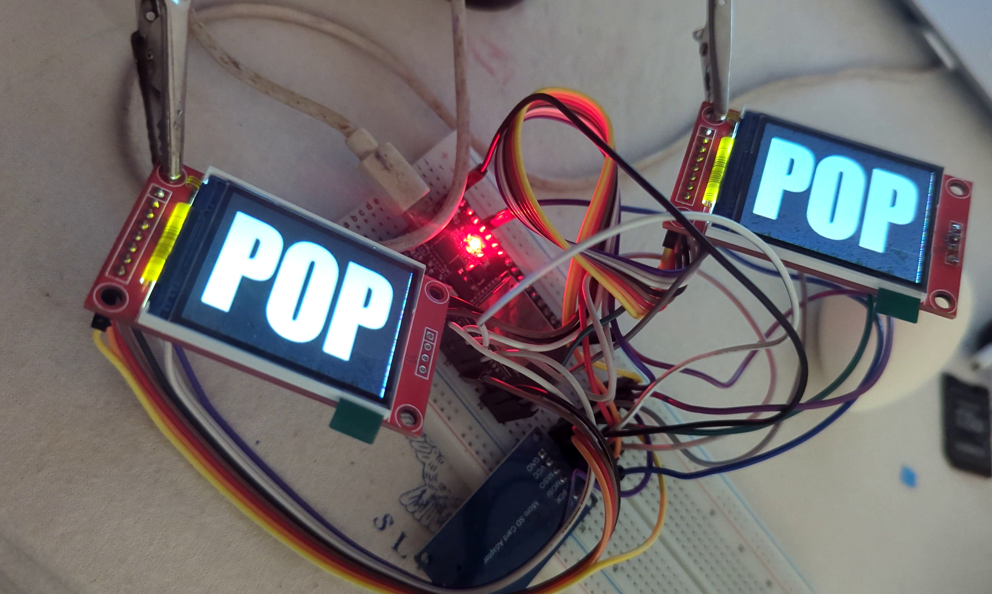
Place the Components
Start by placing your main components:
- ESP32
- Two ST7735 TFT display modules
- SD card module
Position them so that:
- The ESP32 sits in the center
- The two displays are on either side
- The SD card module is easily accessible
Set Up Power Rails
Use the breadboard power rails:
- Connect 3.3V from ESP32 → positive rail
- Connect GND from ESP32 → negative rail
Then connect:
- Both TFT VCC pins → 3.3V rail
- Both TFT GND pins → GND rail
- SD VCC → 3.3V or 5V (depending on the module you have)
- SD GND → GND
💡 Make sure all components share a common ground.
Connect Shared SPI Lines
Now wire the shared communication lines:
- GPIO18 → SCK of both TFTs + SD
- GPIO23 → MOSI of both TFTs + SD
- GPIO19 → MISO of SD only
👉 You can use short jumper wires to split these connections across the breadboard.
Connect Control Pins
TFT Display 1
- GPIO5 → CS
- GPIO16 → DC
- GPIO4 → RESET
TFT Display 2
- GPIO17 → CS
- GPIO21 → DC
- GPIO22 → RESET
SD Card Module
- GPIO13 → CS
Backlight Connection
- Connect both TFT LED pins directly to 3.3V
- (This keeps the displays always on)
First Power Test
Before uploading code:
- Plug in the ESP32
- Check:
- Both displays light up (backlight on, white)
- No loose wires, glitches
Uploading the Code & Troubleshooting
Now that everything is wired and tested on the breadboard, it’s time to upload the code and bring the project to life.
⬆️ Uploading the Code
- Open the Arduino IDE
- Paste or open the provided Arduino sketch
- Connect your ESP32 via USB
Select the correct settings:
- Board: ESP32 Dev Module (or your variant)
- Port: Select the correct COM port
- Click Upload
▶️ What Should Happen
After uploading:
- Both ST7735 TFT display screens should turn on ( Congratulations you are so lucky !!!)
- GIF animations should start playing from the SD card
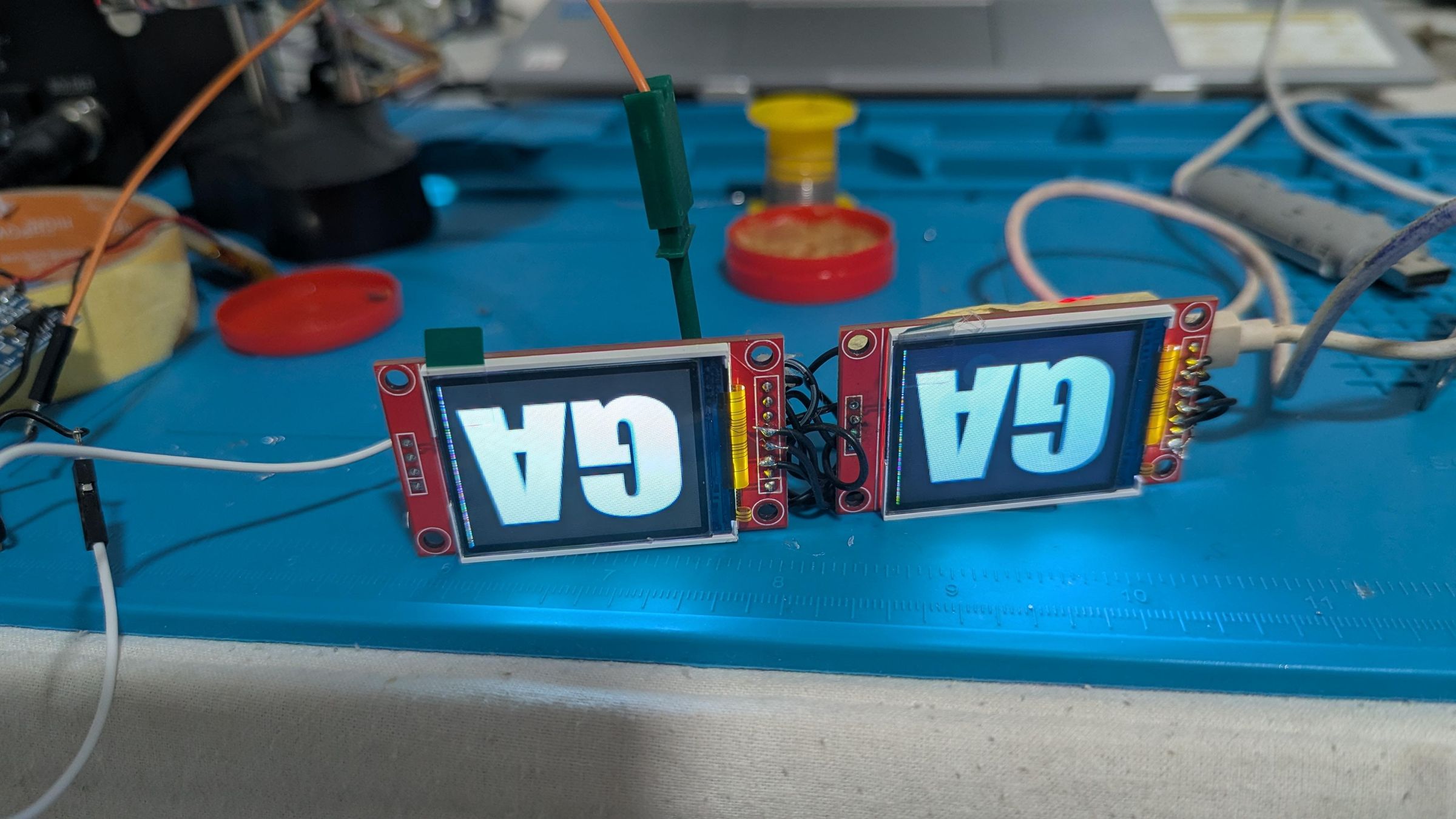
- Both displays should show the same animation in sync
🛠️ Troubleshooting Guide
Here are the most common issues and how to fix them:
CHECK WIRING !!!
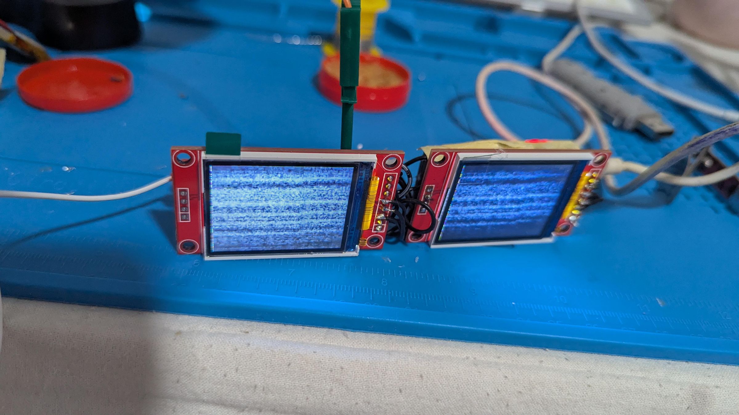
🎨 Colors look wrong / inverted
Causes:
- SPI signal instability (too fast)
- Slight wiring issues
Fix:
- Try disconnect from the power and power back on
💾 SD card not detected
Check:
- SD CS pin (GPIO13)
- MISO connection (GPIO19)
- Card format → must be FAT32 !!!
🔄 Code uploads but nothing happens
- Make sure file names match exactly:
- Check Serial Monitor for errors
💡 Pro Tips
- Start with lower SPI speed, then increase gradually
- Always test on breadboard before soldering
- Keep wiring neat for best performance
Downloads
Final Assembly (Soldering & Mounting)
Plan Before Soldering
Before you start soldering:
- Decide where each component will sit
- Keep displays symmetrical (important for wearable use)
- Plan for short SPI wires
💡 A little planning here saves a lot of frustration later.
Solder the Connections
Using your verified wiring:
- Create solid joints for:
- Power (3.3V & GND)
- Shared SPI lines (SCK, MOSI)
- Control pins (CS, DC, RESET)
💡 Recommended approach:
- Make small junction points for shared pins (SCK, MOSI, 3.3V)
- I connected LED backlight pins to 5V for increased brightness, add a resistor if you needed
- Avoid long wires
- Keep connections neat and secure
Keep Wiring Clean and Short
This is very important for performance:
- Keep SPI wires as short as possible
- Avoid crossing wires randomly
- Use consistent wire lengths for both displays
👉 This helps maintain stable high-speed communication.
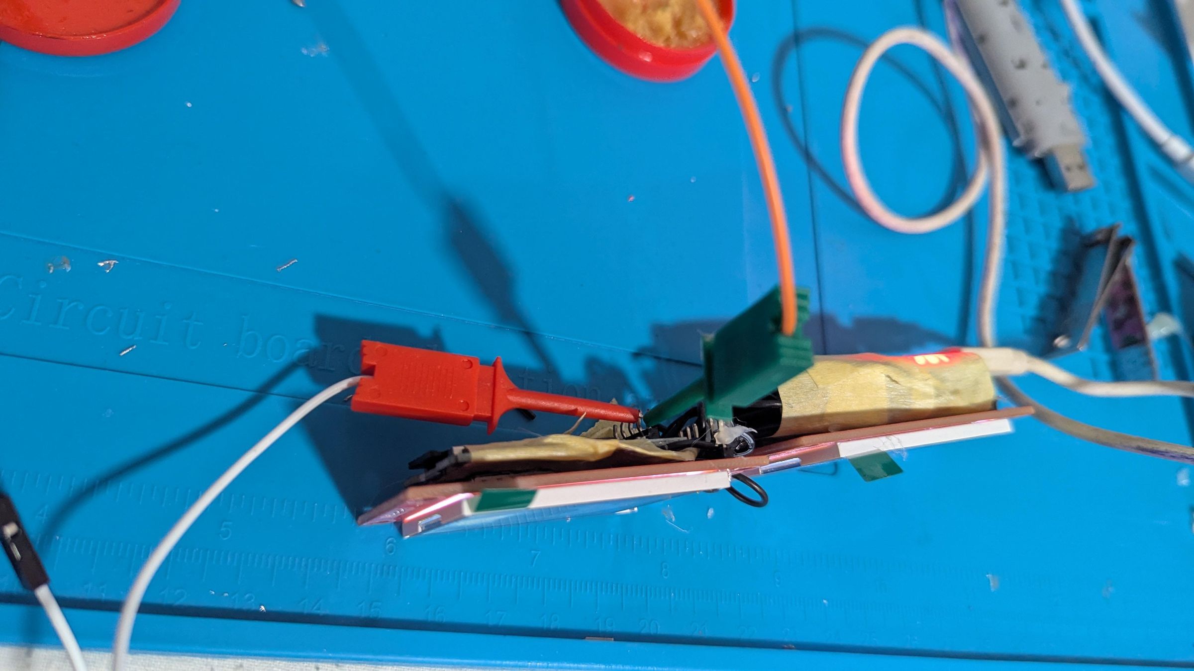
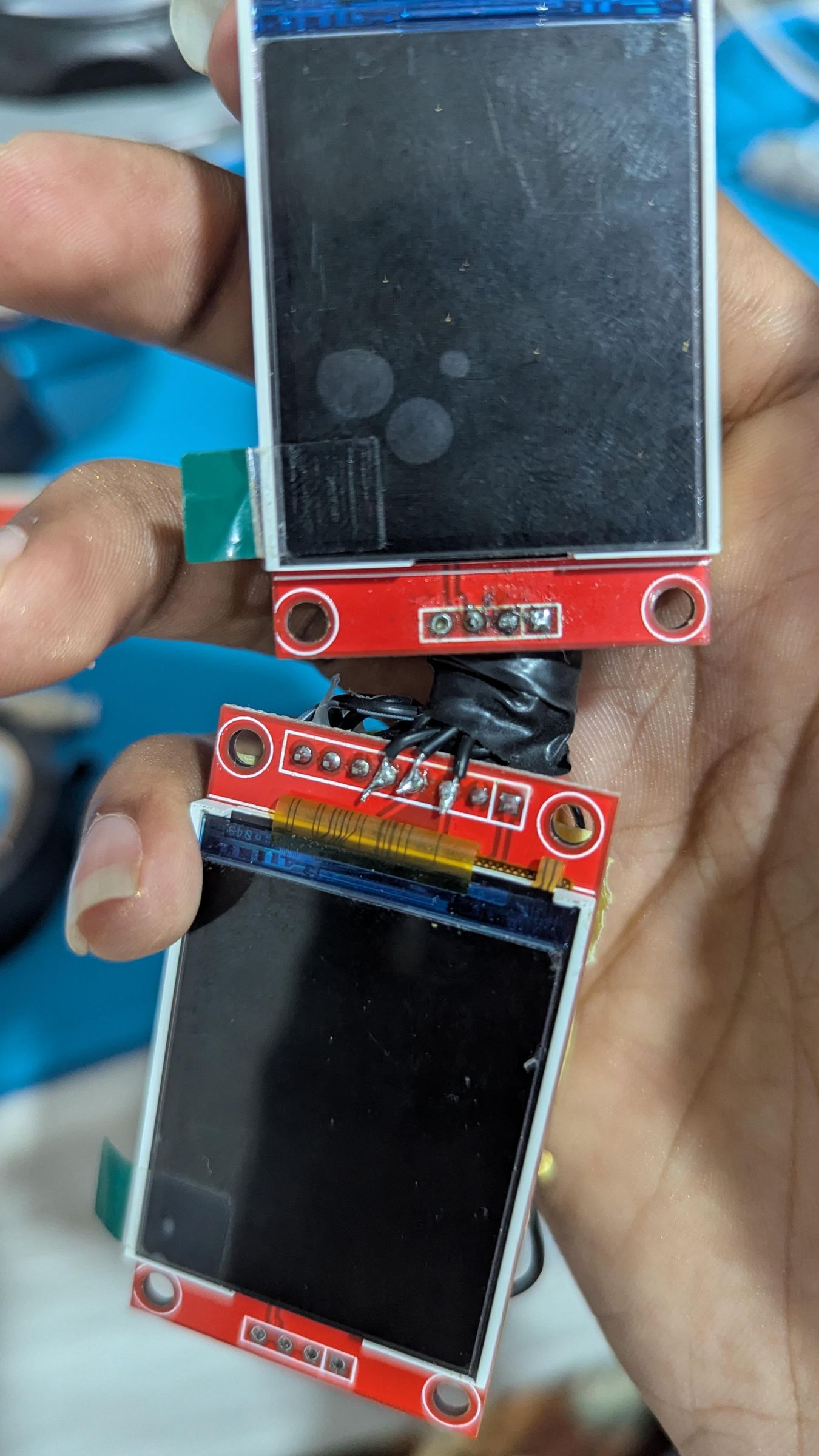
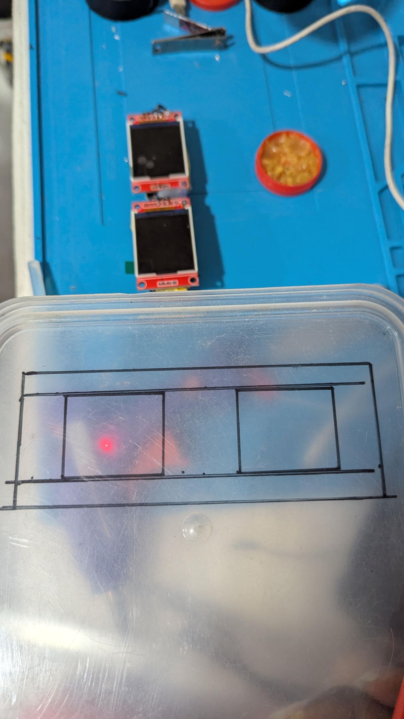
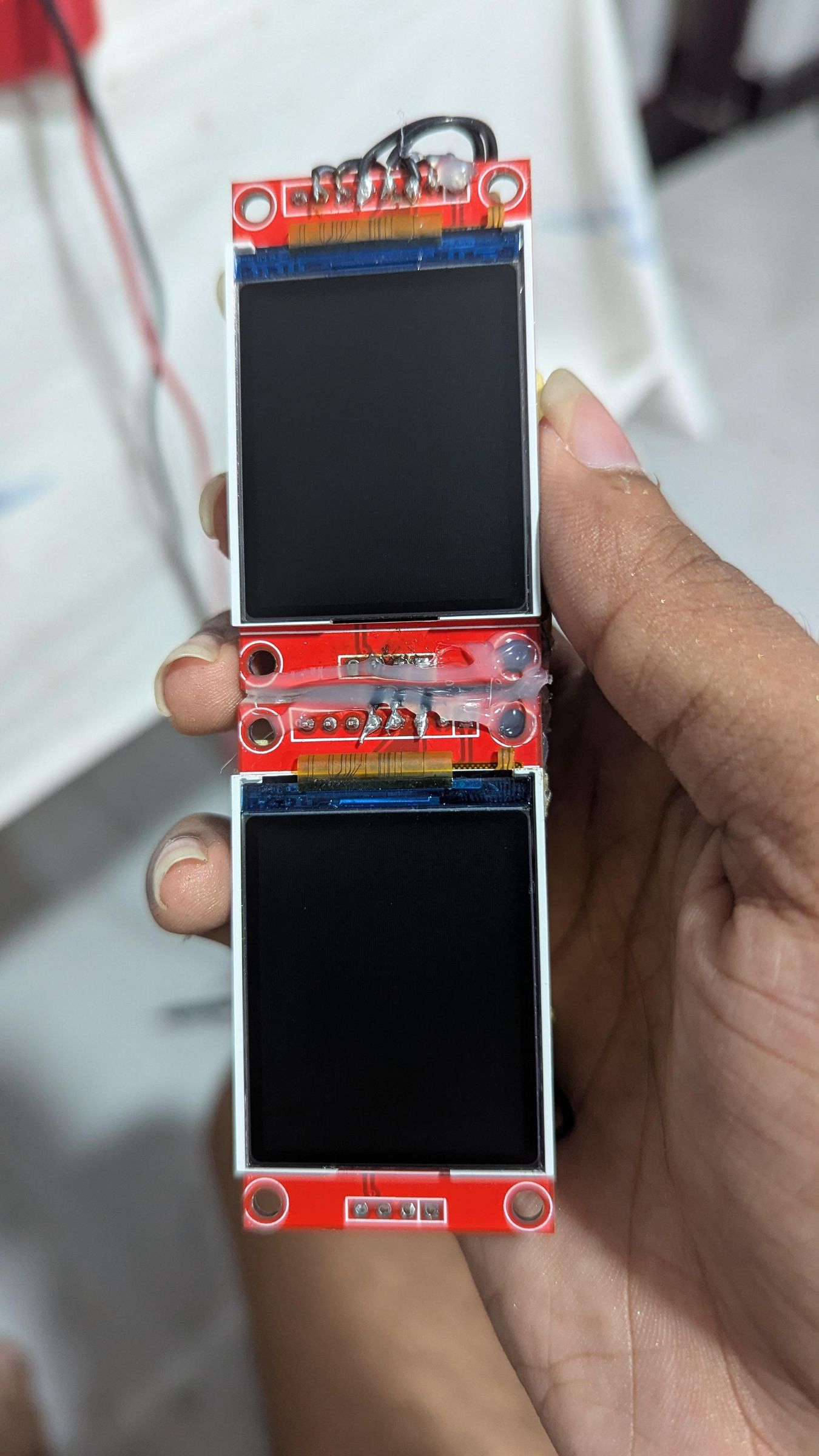
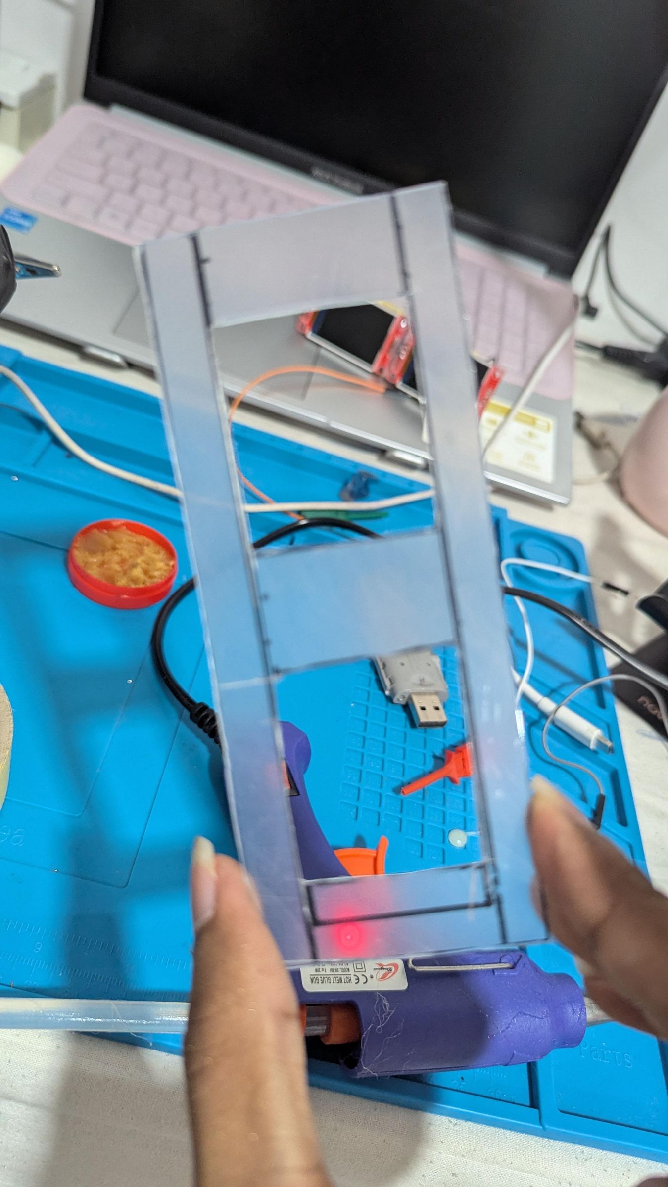
Mount the Components (Refer images to take an idea)
Depending on your design, you can:
Option 1: Wearable (Glasses / Visor)
- Mount the two ST7735 TFT display modules side by side
- Align them with your eyes
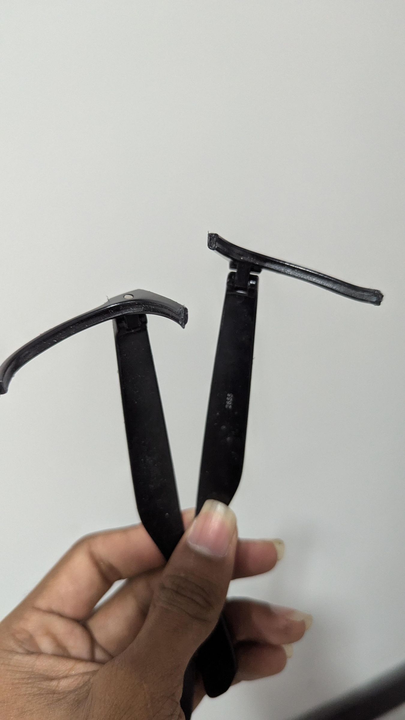
- Use a hard plastic sheet to cut out a frame and place components on it, then glue the old sunglass frame
- Place the ESP32 behind the on one Eye, you can place everything on back of the head also, make sure wires are not too long
Option 2: Compact Module
- Stack components behind the displays
- Use Tape and cover the metal contacts of the components without shorting out
Secure Everything
- Use:
- Hot glue
- Double-sided tape
Power Setup
You can power the system using:
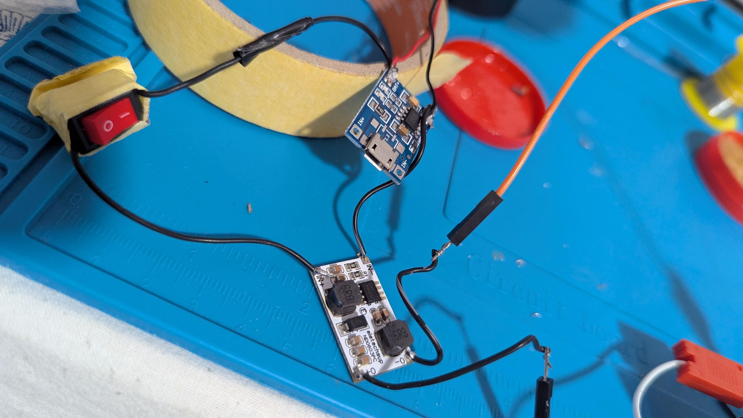
- LiPo battery + 5V Boost Converter + TP4056 sharging module with a toggle switch
Final Test
After assembling:
- Power the system
- Check:
- Both displays turn on
- GIFs play smoothly
- No flickering or glitches
⚠️ Final Checks
- No exposed wires touching each other
- Strong solder joints
- Secure mounting
- Stable power connection
🎉 Done!
You now have a fully working LADY GAGA LCD Glasses !!! Now dance to the Fame !!!.
https://vt.tiktok.com/ZSH1f6stR/
Share your thoughts on this !!!