Laser Cut 3D Instructables Robot Model
by dgouws123 in Workshop > Laser Cutting
422 Views, 3 Favorites, 0 Comments
Laser Cut 3D Instructables Robot Model
This Instructable describes a method to adapt (using LightBurn) 2d bitmap images (with simple colour pallettes) for laser cutting and constructing a 3D representation of the image. The image is traced to a vector representation, sliced and disassembled. Different features of the image are grouped, cut and engraved on the corresponding MDF layer.
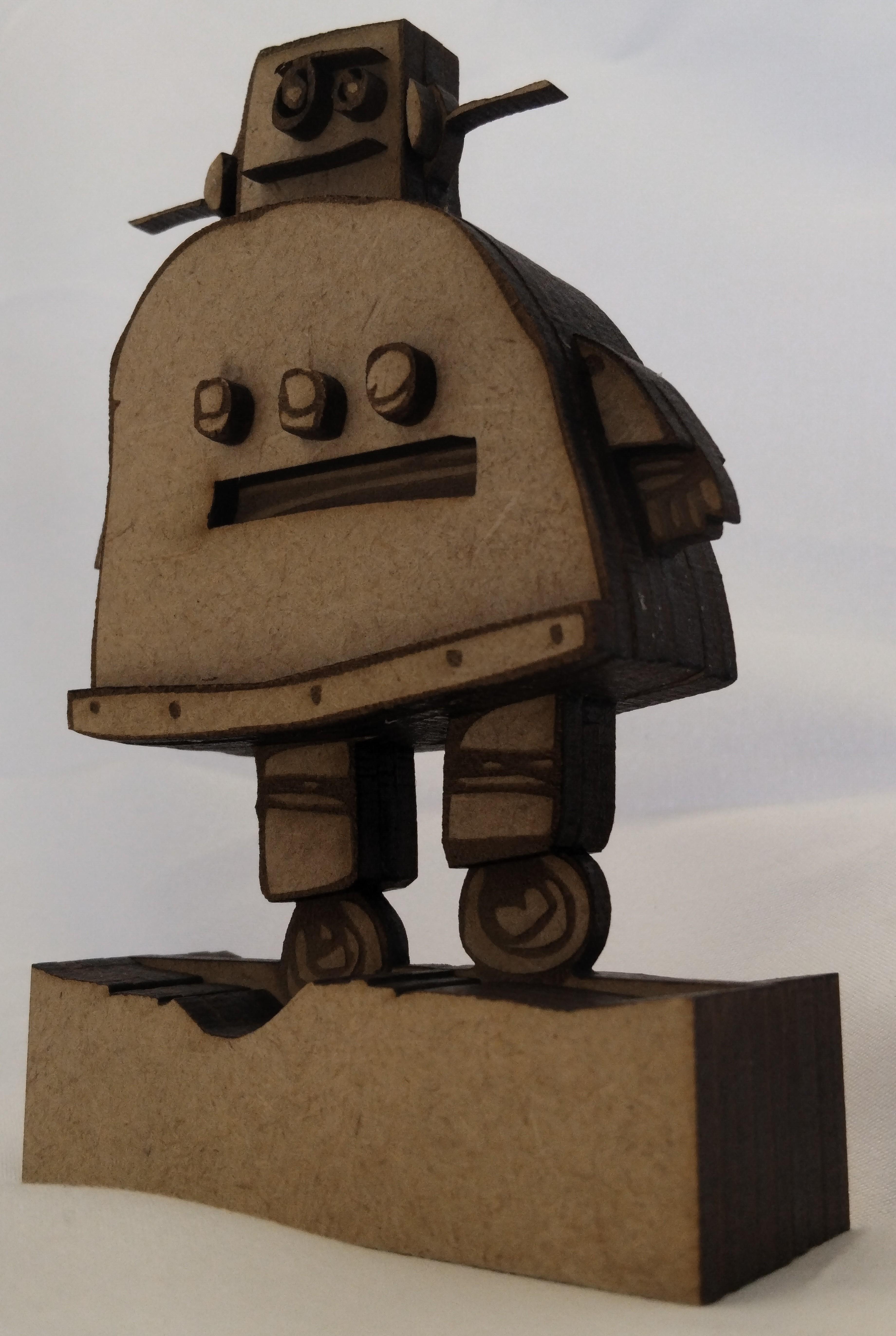
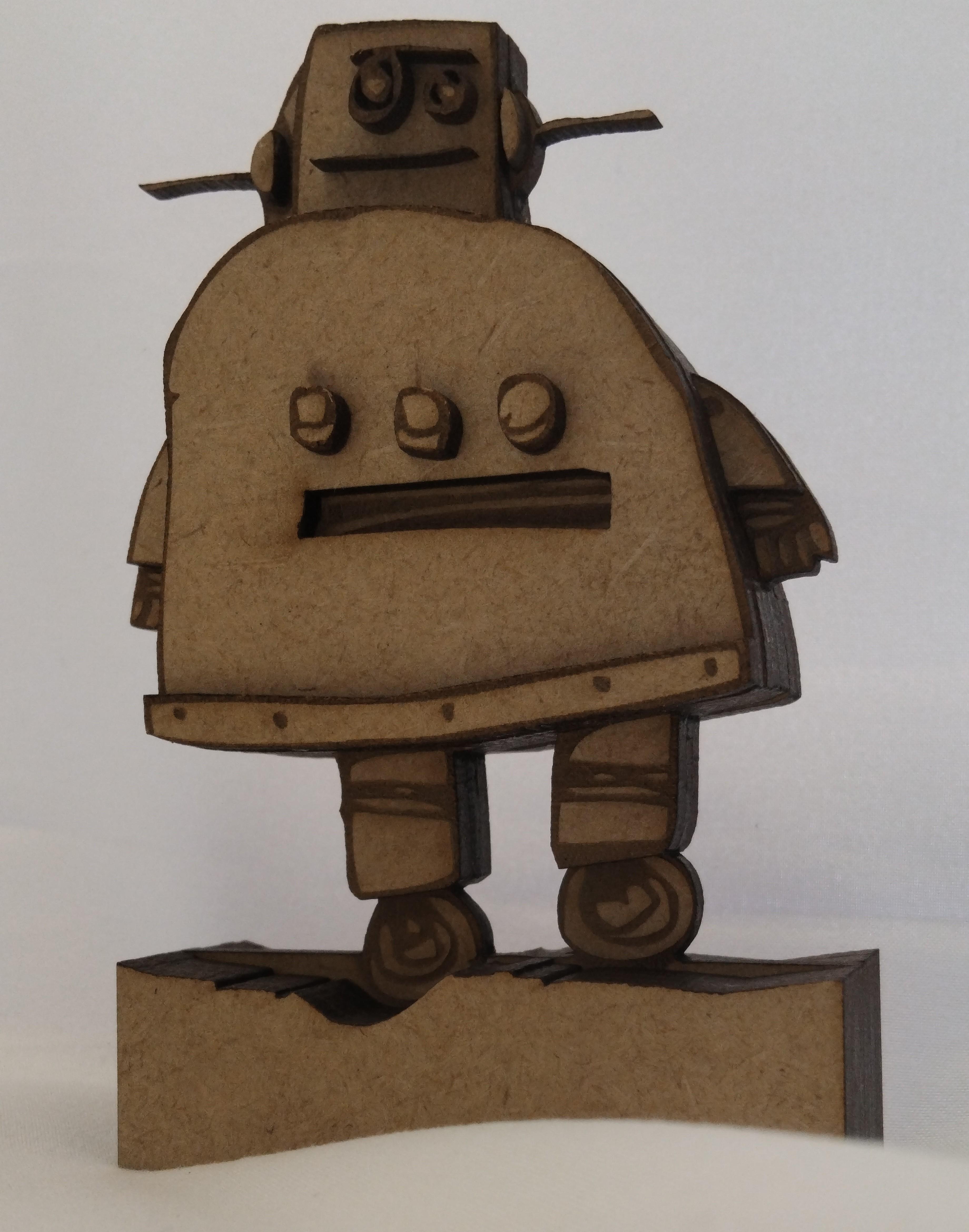
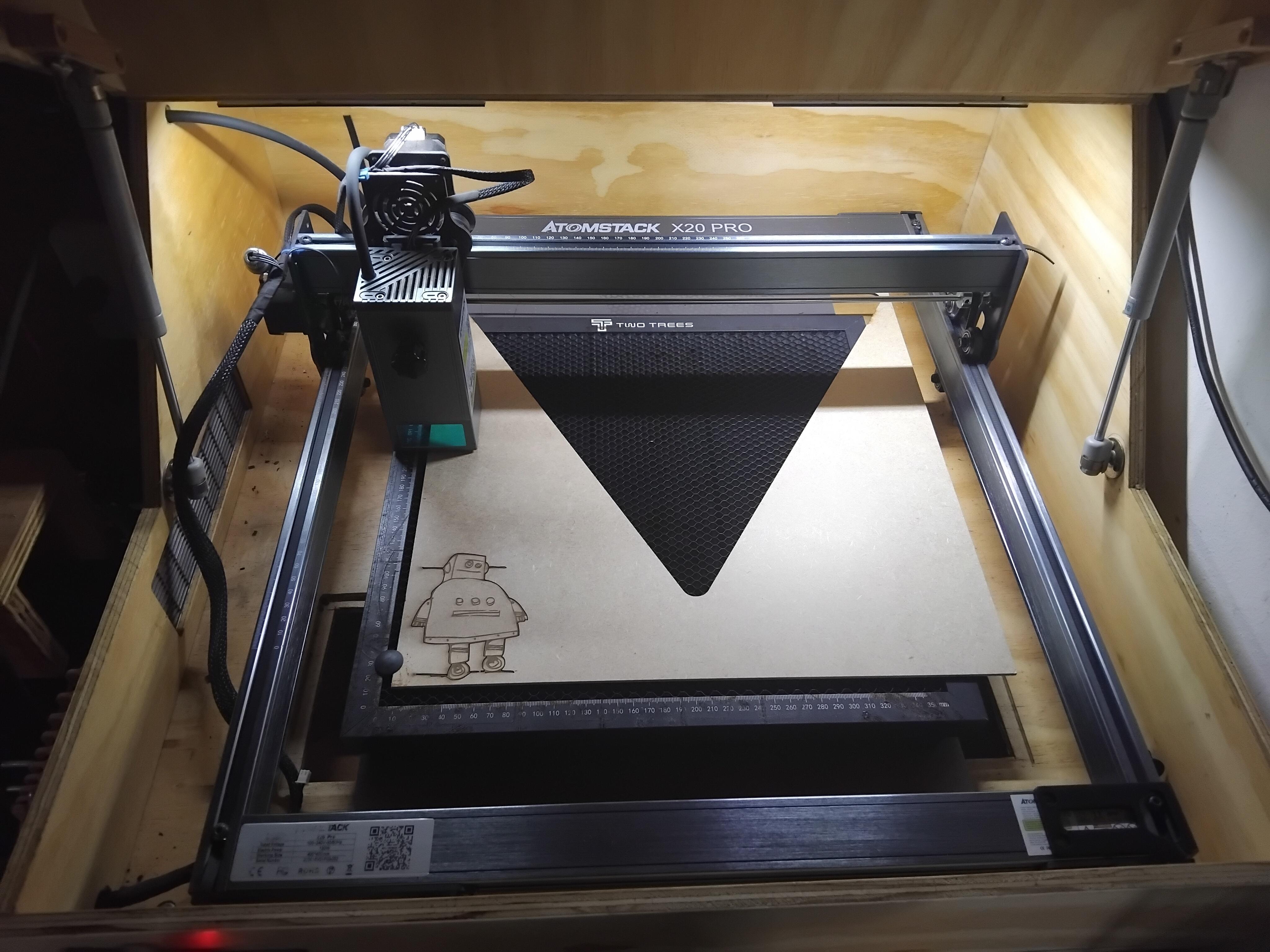
I wanted to bring the Instructables robot into the 3d realm, according to my own interpretation, personal expertise and available technology. I had access to an Atomstack X20 Pro laser cutter for this project. In order to create an accurate representation and limit the project to be mostly technical, the original Instructables logo is used with minimal modification. The model will be built up using multiple sheets of MDF(Medium Density Fibreboard) to give step depth and thickness to the different features of the robot. Additionally, the details on the robot will be laser-engraved on the model.
Unfortunately, experience shows that it is usually frustratingly difficult to adapt existing images into workable designs for manufacturing when the process imposes requirements not originally taken into account. In this regard, I present a step-by-step method for adapting simple 2d images to this type of manufacturing process (laser cutting, engraving and stacking MDF). The method can be extended to produce 3D laser-cut models with detailed engraving from similar images.
I also wished to demonstrate that laser-cutting with MDF sheets is a rapid alternative to 3D printing when prototyping small to medium-sized objects. Although this is typically limited to 2D objects, creative application of multiple layers of MDF allows for objects with variable thickness.
The design is done around the abilities and restrictions of a Diode laser cutter. Some experience with LightBurn or laser cutting and etching in general will make design choices and explanations clearer.
Supplies

The following is required:
- A diode laser cutter. Preferably 20W or more. A 5W laser would be very slow.
- Several 4mm MDF sheets. Ensure you get the type suitable for laser cutting. Some types only ash and burn and don't cut properly.
- Wood glue
- A suitable image to cut. Further details in the next step.
- Access to LightBurn (Or an alternative laser software with vector shape editing ability if available). Note that LightBurn is paid software but has a 1-month trial period. I'm using version 1.4.05.
- Enough persistence and motivation to reach the end. Some things are finicky.
Find a Suitable Image
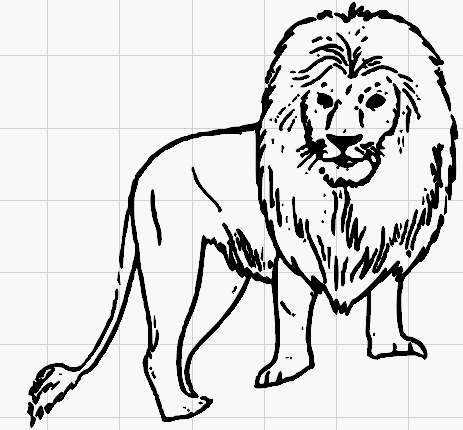
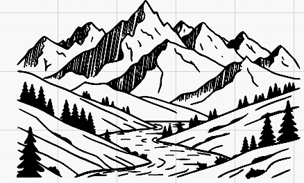
Find a simple vector image or a bitmap image created from a vector image. Look for images with clearly separated depth layers. Ultimately, laser cutters can only produce very limited shades of colour. Images should be chosen such that the critical features are not ruined by this limitation but rather accentuated by it. Thin lines may create problems, and gradients will likely be omitted during the trace.
Some suitable examples are attached. Originals found here:
Trace Bitmap to Get Vector Image
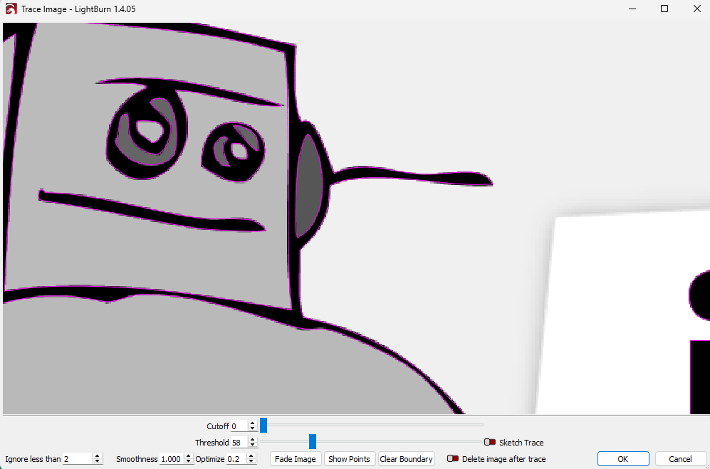
Lightburn requires the images to be in a closed-loop vector format for laser cutting. Engraving of bitmap images is a different field.
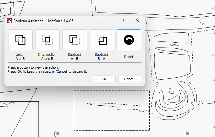
Lightburn has a very effective, highly recommended built-in trace functionality. An image of the trace tool in action is attached. The tool assumes you have a desired image of a single colour caught between a lighter and a darker colour. It attempts to place line loops on the thresholds between the three colours. "Threshold" sets the border on the lighter colour and "cut-off" the border on the darker colour. These can be adjusted to capture the colour borders you deem most important. Note that the operation can be repeated and the loops aligned and combined if you wish to capture more than three colours.
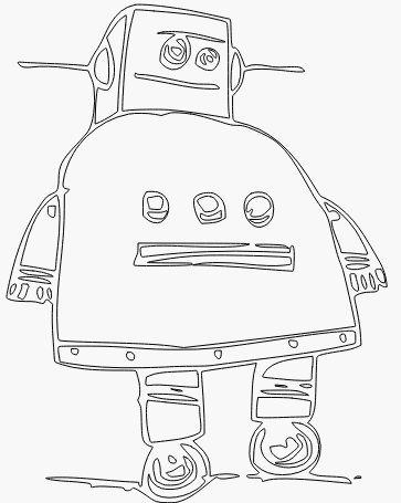
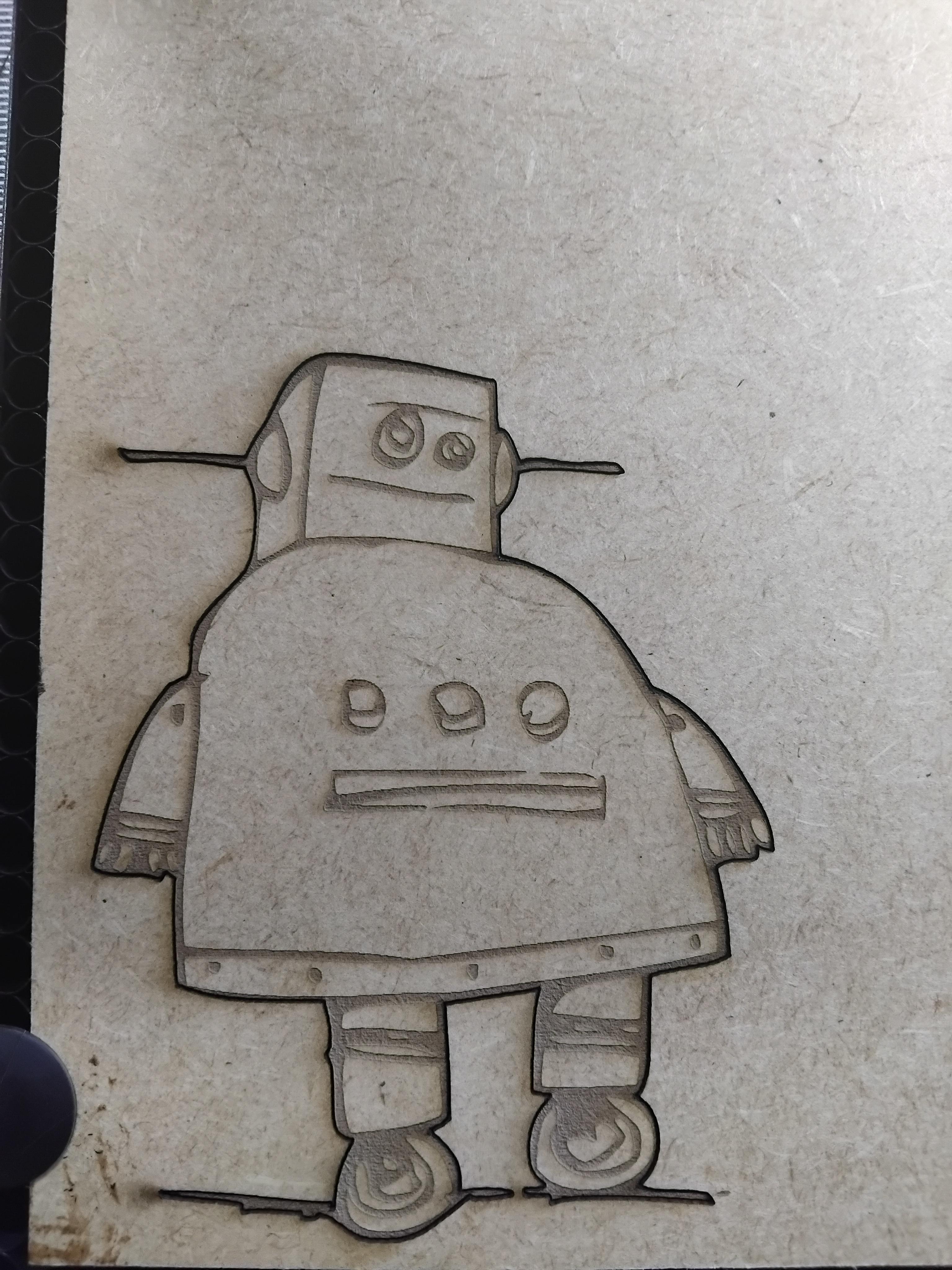
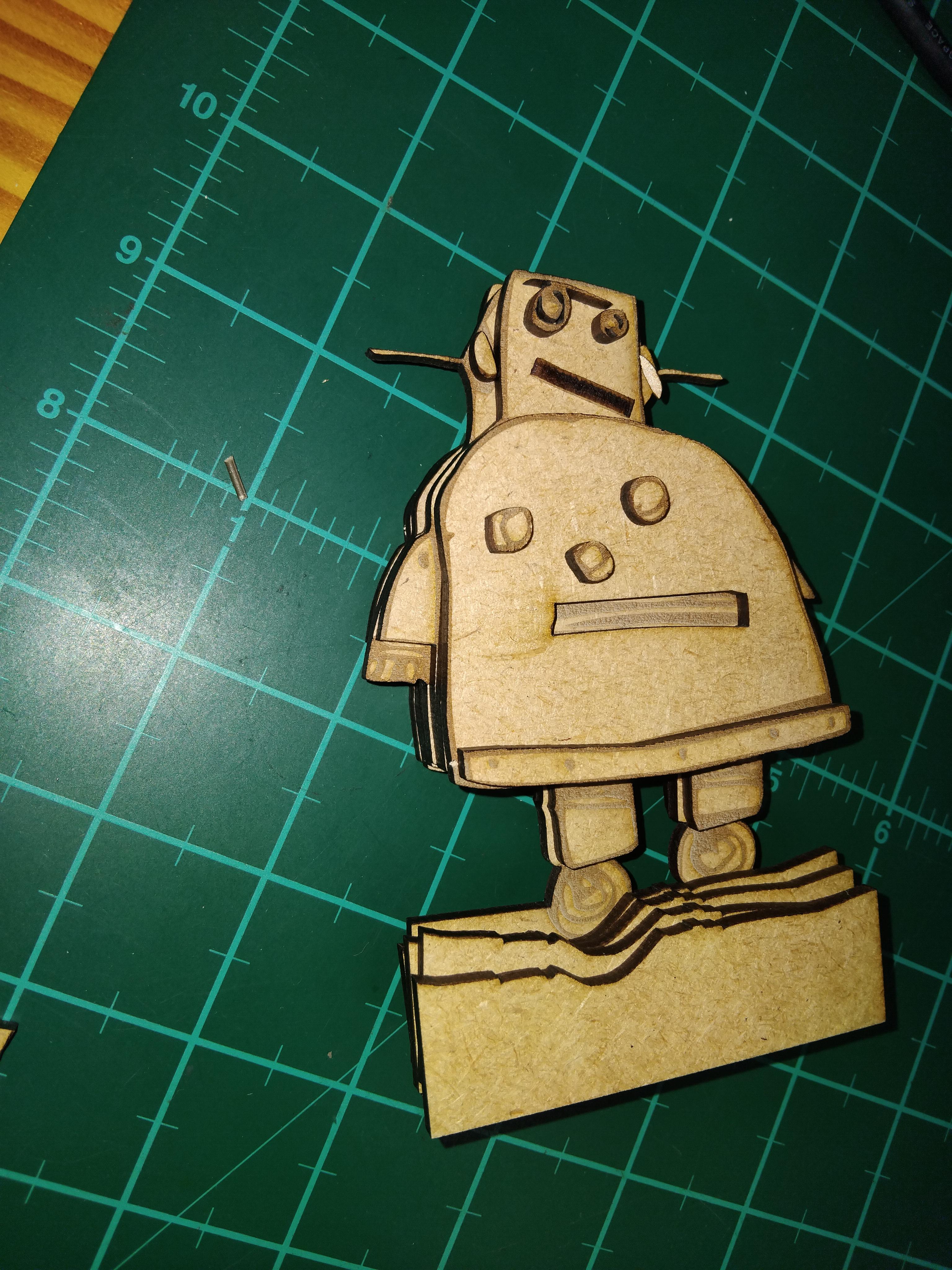
Now that you have a traced image, you could cut the outline and engrave it on a single layer of MDF as is normally done (see image) and get a good result. However, laser cutters give access to the 3d world (especially if not afraid to eat through MDF sheets). I believe leveraging this allows for much more artistically impressive works.
Consider Which Features to Place in What MDF Layers
We need to plan how to realise the design in three dimensions. Think about how you want to interpret the 3D nature of the object. Which parts should pop and be highlighted, and which should be sunken into the background?
For this robot, I view it as having a chubby frame with a small head, arms and legs and thin hands and wheels. The knobs on the body stand up while the slot is sunken in. The strip at the bottom is riveted over the body. For stability, the whole setup should be mounted to a base.
To manufacture the model, the above should be translated into which features are exposed on what layer of MDF. For the robot:
- Hands and wheels are on the central layer. The head side panel is also exposed here
- The arms and legs are on the next layer to add thickness and a clear step height difference. Also, add the ears and face layer here.
- The next layer is the eyes and the slot.
- Next is the body.
- Finally, the Buttons and the lower strip are added.
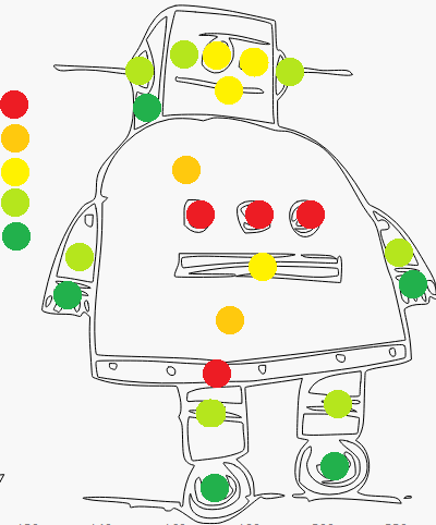
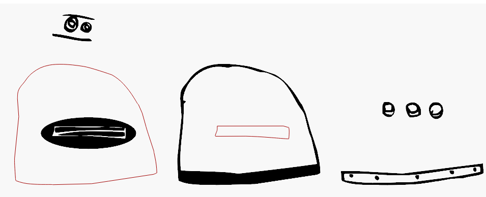
A colour-coded image is attached to clarify the feature split. This totals to 5 Layers of MDF. It is practical to add more if a greater thickness is desired.
Overview of the Adaptation Process


The easiest way to create the design for a given layer is to start with the full trace of the robot and cutting away everything that shouldn't be on that layer. Start at the central layer and gradually work outwards. Cutting is done either using boolean operations or directly editing the nodes of the vector image. As we move up in layers, more and more is cut away.
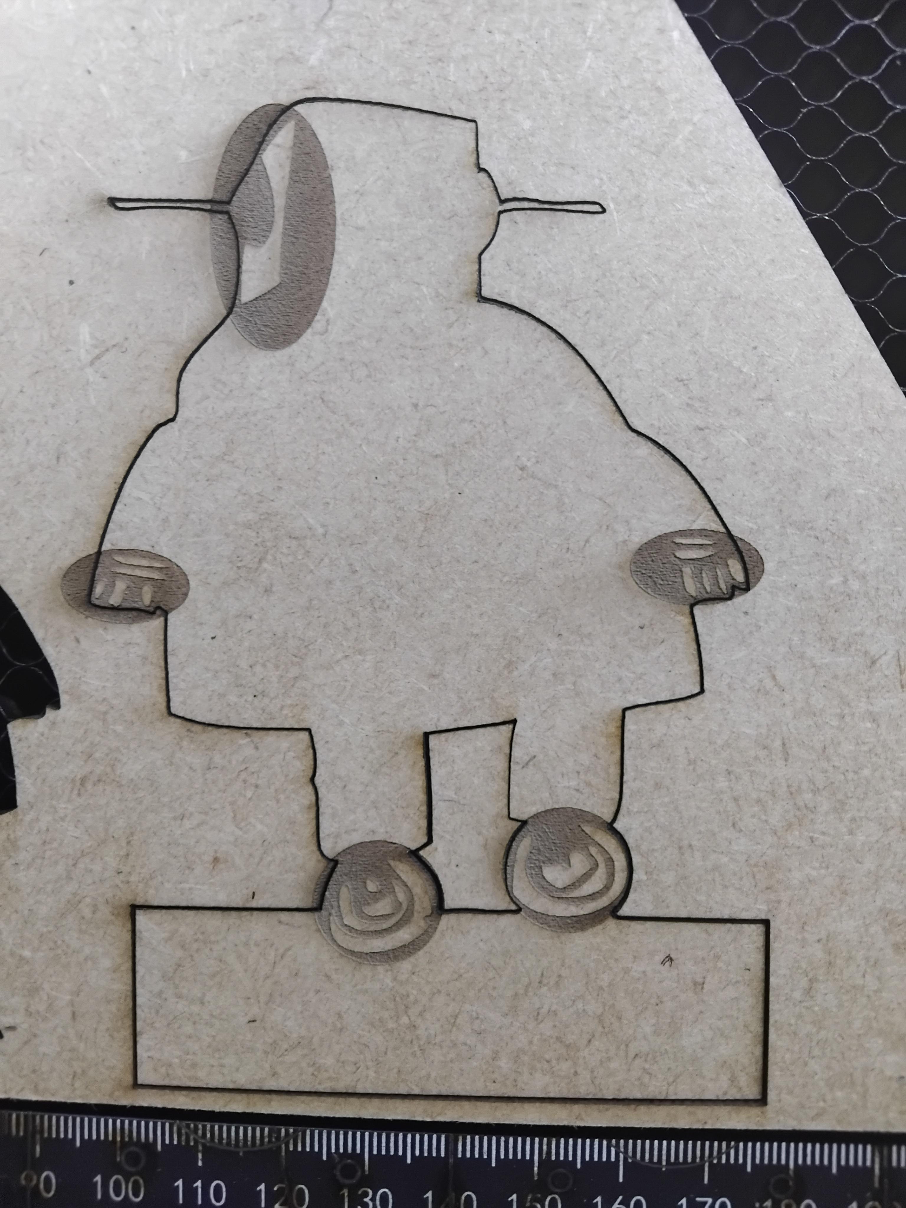
The first MDF layer contains the entire outline. This should be combined (see image of boolean union) with a rectangle for ground stability, since the wheels aren't level. Use a boolean subtract (see image) to remove dirt splash next to wheels and clean up with node editing (see image). As mentioned in the previous step, the wheels and hands are exposed on this layer. After making sufficient copies of the geometry and shifting them out of the way (shift + arrows), delete inner features except for those on hands and wheels.
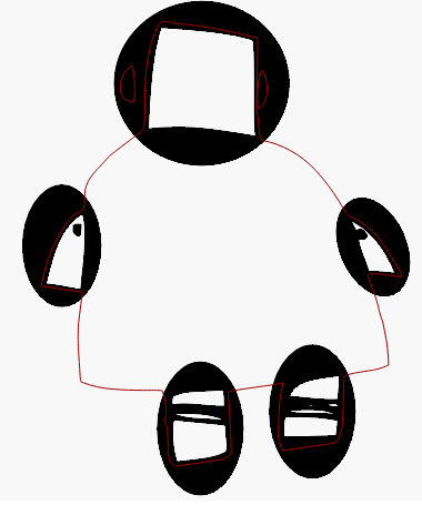
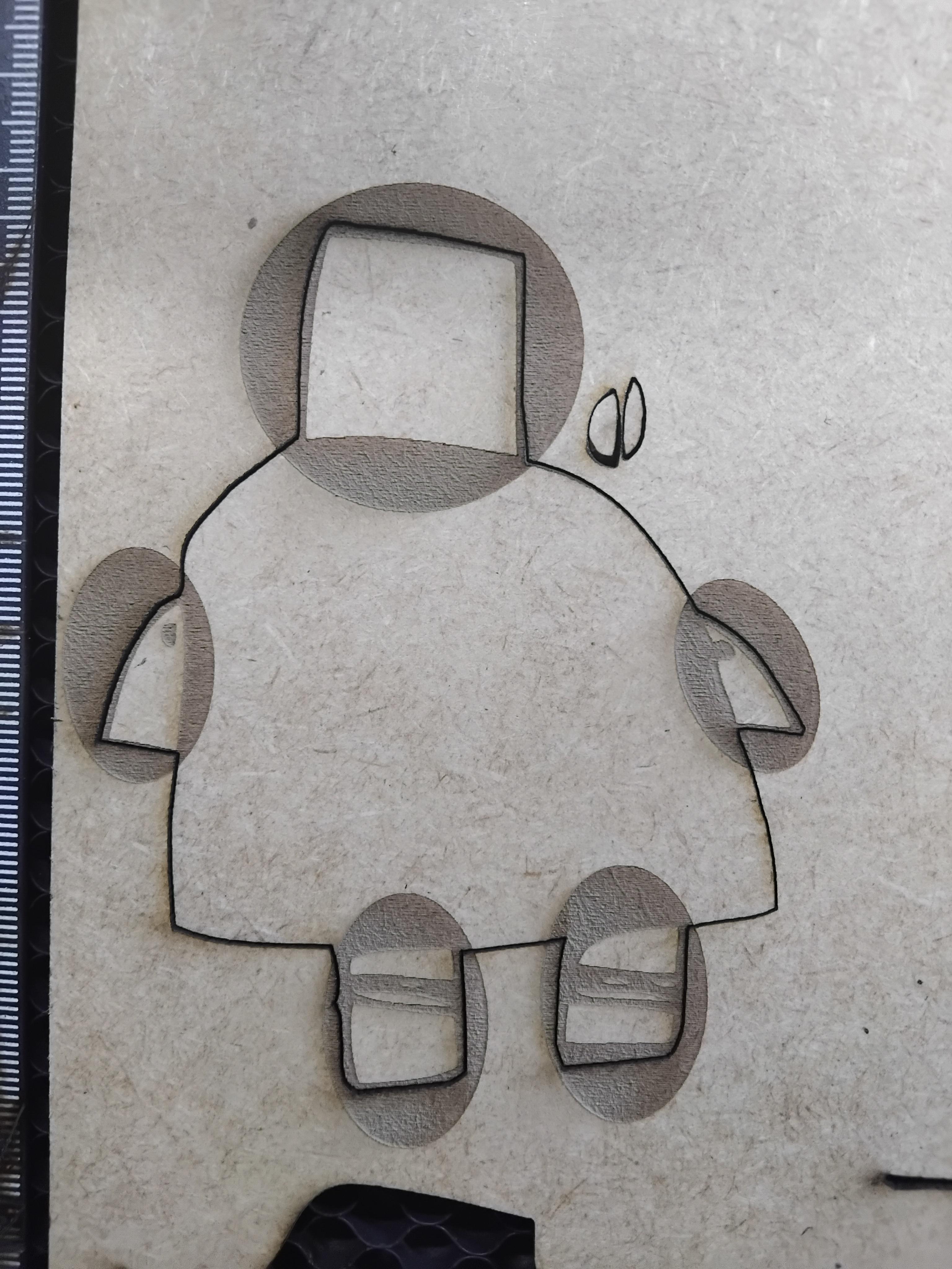
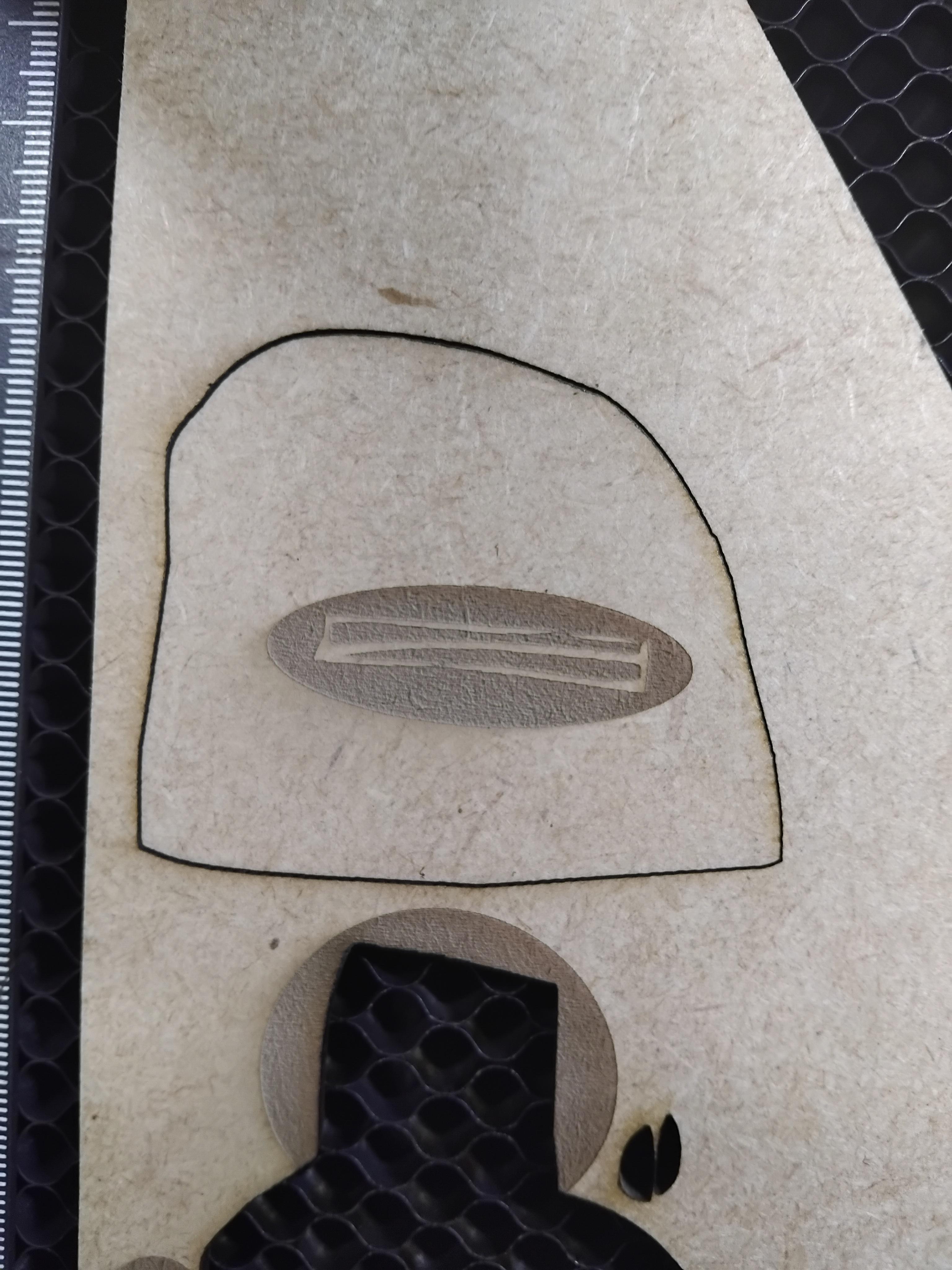
Currently, the fingers are correctly etched (colour not inverted if we reuse the outline for cutting and etching), but so is the entire robot (see image of black robot). Although this will be hidden under the next MDF layer, burnt, rough edges may be visible, and the etching time will be significantly longer. This can be resolved by not using the outline for the etch. Instead, we replace it with a much smaller, simple bounding shape (an oval or rectangle) to act as the new etch boundary (see image of red outline for cutting and black ovals for etching). Now we get some etching of the area outside the robot, but the total etch area (and the etch time!) is greatly decreased.
The centre layer is now ready to be cut and etched.
Layer 2
We follow the same procedure as with the centre layer, but this time the hands and wheels have to be cut away. Start again with the geometry of the full robot. Add shapes to cover the hands and wheels. Use boolean subtraction to remove those segments and create a new outline. Fix the jagged edges created by the Boolean subtract using node editing (ctrl + `). Delete the inner features except those on the arms and legs, and add boundary shapes to get the area to be etched correctly.
As mentioned in the feature to layer plan, the ears are also exposed on this layer. They are used as an outline and are cut.
Note that LightBurn allows grouping to select multiple geometry pieces with a single click. Additionally, groups can be grouped and will retain their subgroups when they are ungrouped. Moving related geometry around is much easier if it remains grouped.
Layer 3 to 5
The other layers follow a similar approach. Note that several duplicates of the rectangular base need to be made to keep the model stable. Notably, the belly slot is exposed one layer below the body. Some top or centre objects, like the buttons and strip, do not use bounding objects for etching but can rather reuse the cut outline as the etch outline. The bottom strip stands out on top of the body layer.
Cut Out on Laser
We assume a laser cutter is available and you are familiar with it. Follow all applicable safety rules, including protective glasses and proper ventilation.
Attempt to cut multiple layers out of a sheet of MDF. Alignment of the different cuts and etches shouldn't be necessary. I leave the back of the robot blank to avoid having to etch one side and realign the layer to etch the other side. Note that double-sided alignment is possible if you are willing to spend more time and material. Cut and etch profiles for the MDF will have to be tuned beforehand for good results. Some layers could be cut twice and stuck together if additional thickness is preferred.
Glue Layers Together
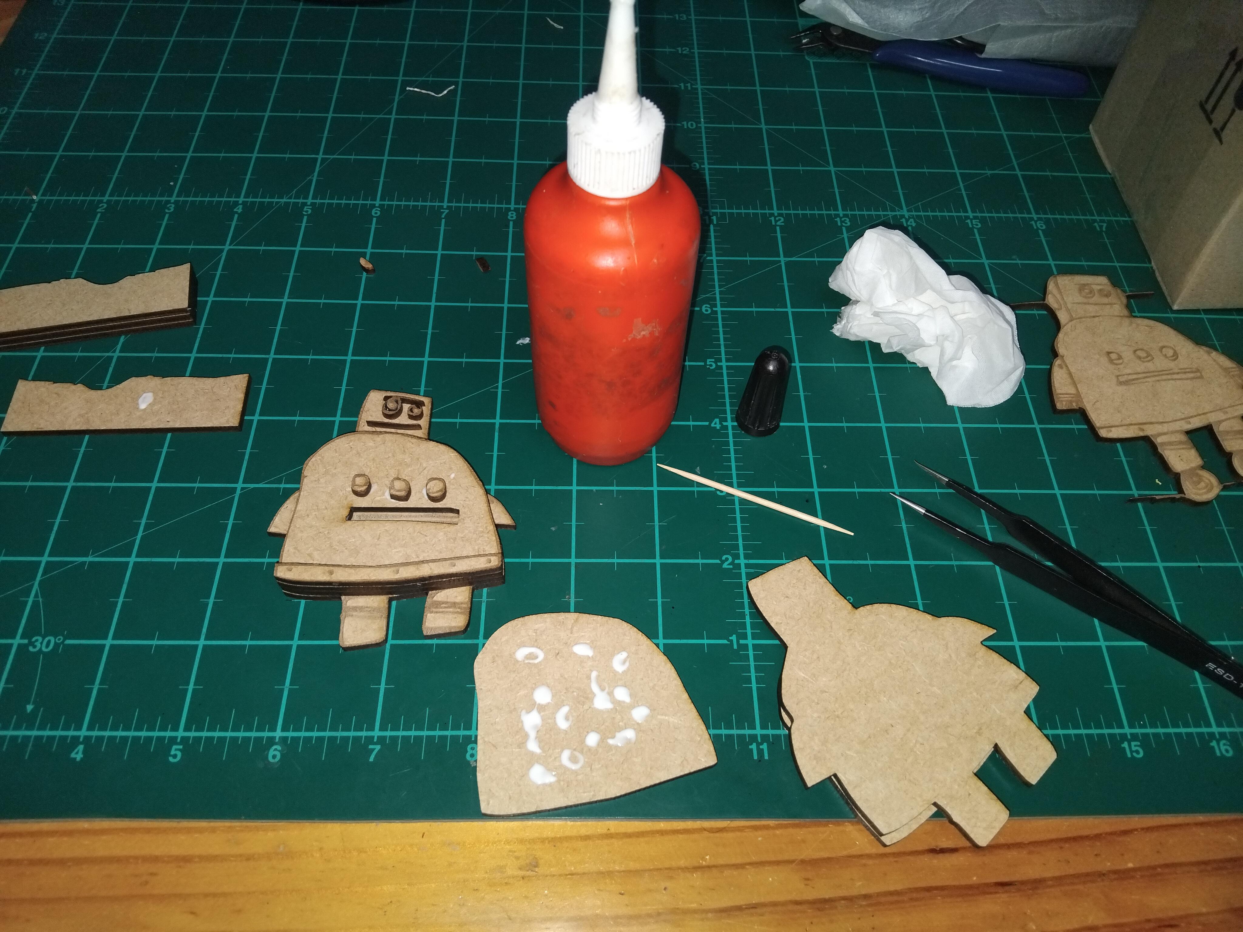
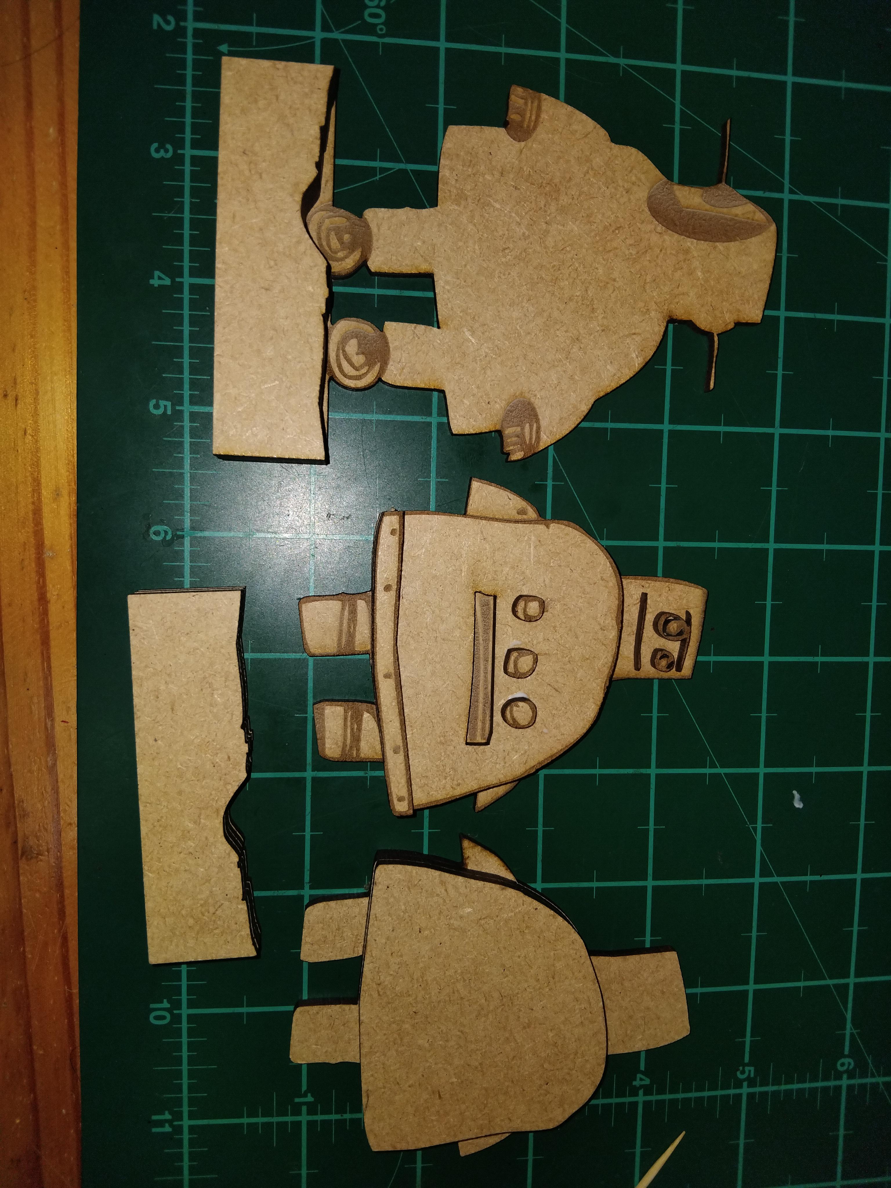
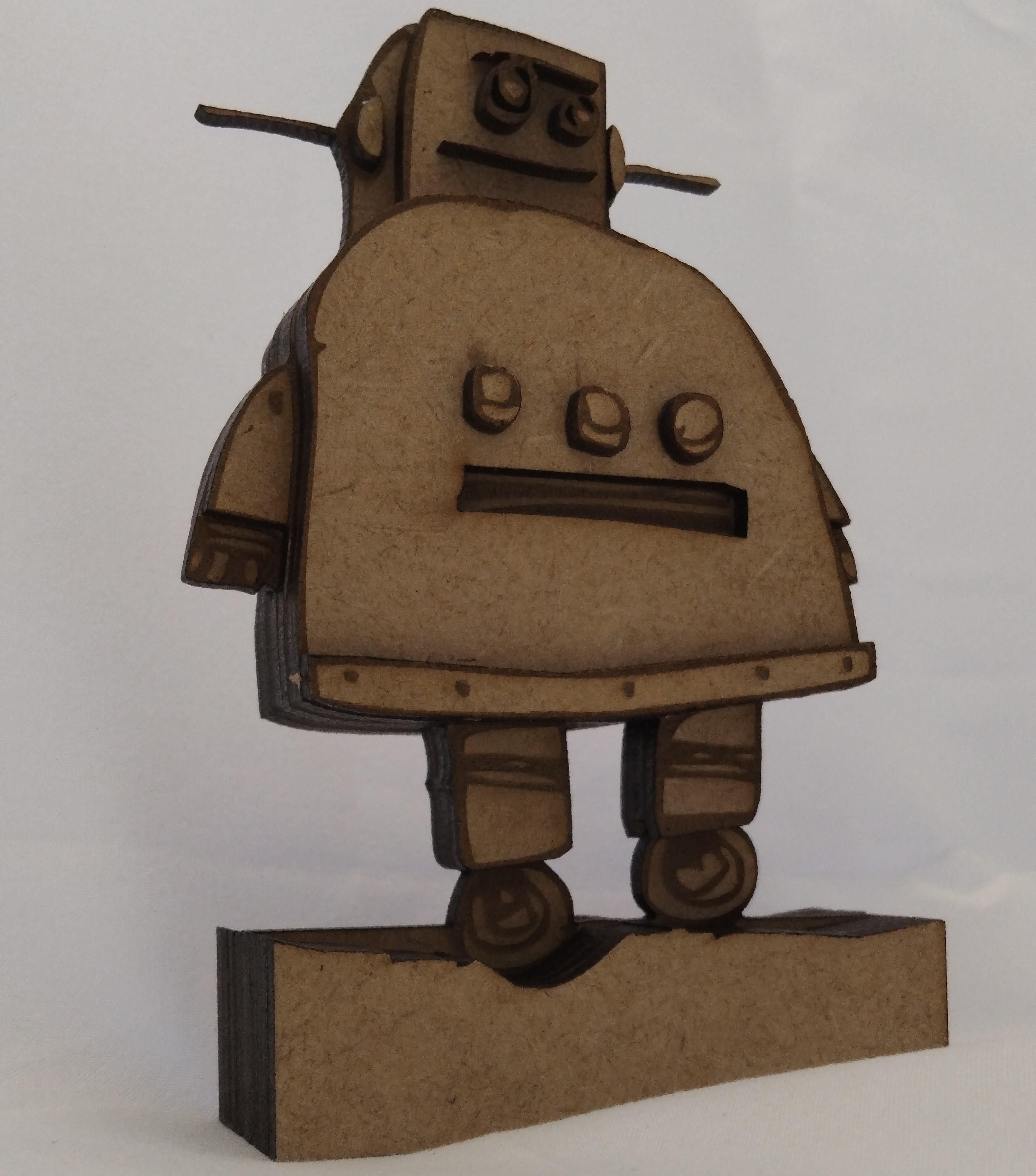
Post-processing shouldn't be necessary. Apply wood glue and stick the layers together correctly. Use a toothpick to apply glue to small components. Use a wet paper towel to remove excess glue. Leave to dry. Hopefully, the result is as you hoped.
Conclusion
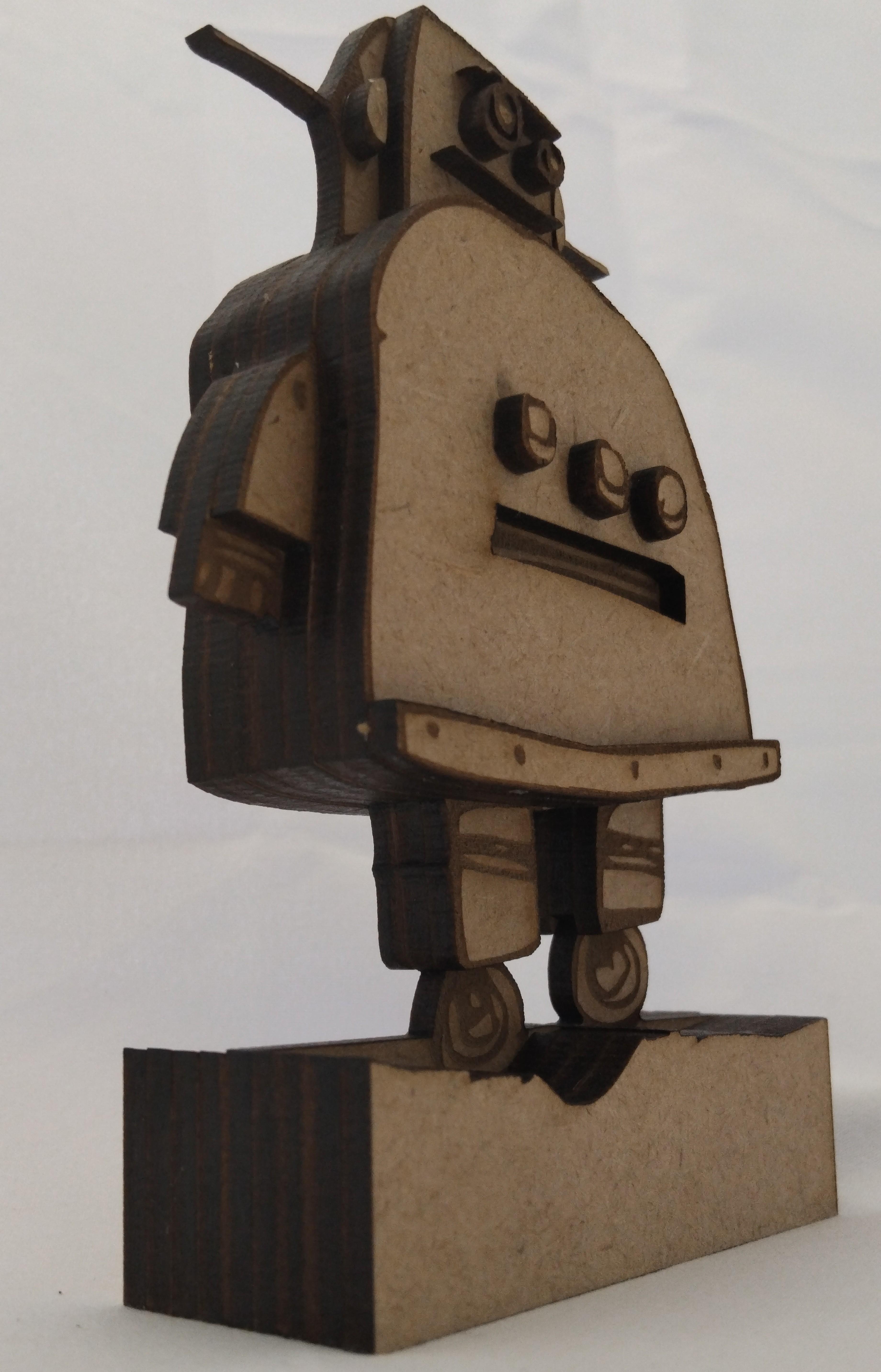
The created model is purely for artistic display and is not meant to be functional. Hopefully, the method can help you bring your own 2d images into the 3d world. The lightburn file for this project is attached.
An extra tip: Laser cutters work well on paper and cardboard when cutting numerous complex shapes. The above model could be further colourised by adding paper cut layers to highlight or cover certain features. Mind that the use of coloured paper might interfere with the semi-natural style of the scorched MDF.
Thanks for reading. Happy Birthday to Instructables.