Launchpad : Build a Wireless Model Rocket Launching System
by The Uncertified Engineer in Outside > Rockets
158 Views, 2 Favorites, 0 Comments
Launchpad : Build a Wireless Model Rocket Launching System
.png)
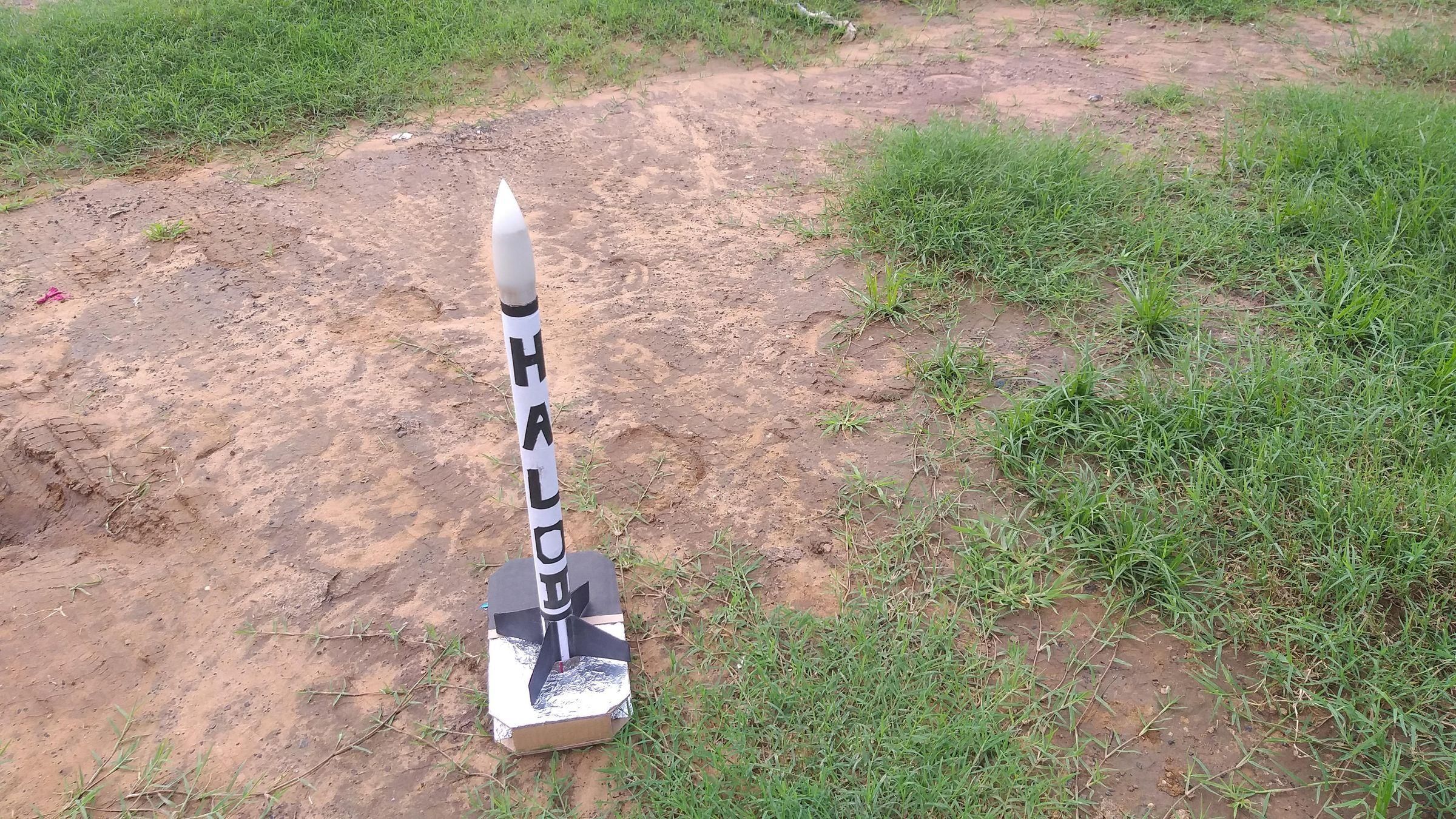
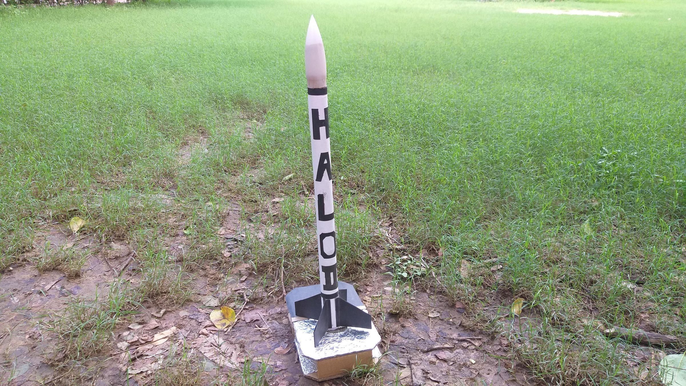
Every backyard rocket launch has that one awkward moment: someone crouches down next to the rocket, touches a wire to a 9V battery, and just... hopes. Everyone else is standing "a safe distance away," which usually means a few nervous steps back. It works, sure, but it's not really safe, and it doesn't feel like the big countdown moment it should be.
I wanted to fix that.
Meet Launchpad — a WiFi-controlled ignition system for model rockets, built around an ESP32, a relay, and a buzzer, tucked inside a heat-shielded cardboard enclosure. Instead of crouching next to your rocket with a battery in hand, you just connect to Launchpad's own WiFi hotspot from your phone — from a proper safe distance — and run the whole launch through a clean little web page.
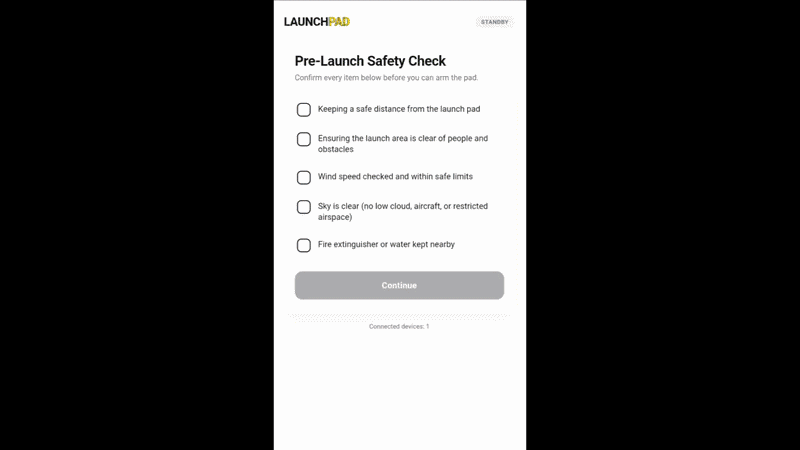
Before you can do anything fun, the page makes you tick off the same checklist any sensible flier already runs through in their head:
- Are we keeping a safe distance?
- Is the launch area actually clear?
- Is the wind okay?
- Is the sky clear?
- Do we have a fire extinguisher or water nearby, just in case?
Only once all five are checked can you arm the pad. Arming takes a deliberate tap, launching needs a solid 3-second hold on the launch button (so no accidental jabs), and then you get a proper 10-second countdown with a buzzer that gets more urgent as it counts down — enough time for everyone to get ready and actually enjoy the moment. And if your phone ever drops off the pad's WiFi while it's armed, it disarms itself automatically. No connection, no ignition. Simple as that.
End result: backyard rocketry that feels less like "hope this wire doesn't spark early" and more like an actual launch console — one that's honestly pretty satisfying to use, whether you're the one flying the rocket or the neighborhood kid who just wants to hold down the big yellow button.
Here's how I built mine.
Supplies
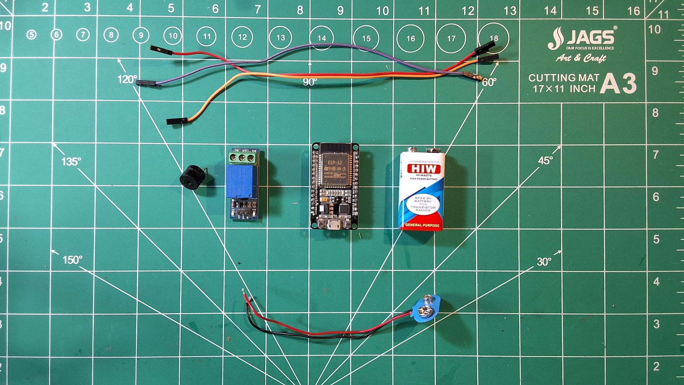
Here's everything that went into building Launchpad — split into electronics, enclosure materials, and tools.
Electronics
- ESP32 Dev Board (WiFi + runs the whole show)
- 1-Channel 5V Relay Module (switches the igniter circuit)
- Active Buzzer (countdown beeps + ignition tone)
- 9V Battery + Battery Snap Connector (power)
- Jumper Wires (male-to-female, for relay/buzzer/battery connections)
- Electric matches or igniters (Ignites the rocket motor)
Enclosure Materials
- Corrugated Cardboard (enclosure body — reused from packaging)
- Aluminum Foil (heat-shield lining inside the ignition chamber)
- Bamboo Skewer (launch rod / igniter guide)
- Glue Gun / Craft Glue
- Tape (for holding foil in place while gluing)
Tools
- Cutting Mat
- Craft Knife
- Ruler & Pencil (for marking cut lines and hole positions)
Safety Notice (Before You Build)
A quick but important word before diving in.
Model rocketry is a well-established, genuinely safe hobby — millions of launches happen every year without incident — but that's because the hobby takes safety seriously, not despite it. Launchpad is designed to support good safety practice, not replace it. A few things worth being upfront about:
- This is a remote ignition controller, not a substitute for judgment. The safety checklist in the web UI is there to reinforce good habits, not enforce them by itself. You are still responsible for actually keeping a safe distance, checking real wind conditions, and using a rocket motor appropriate for your setup.
- Follow your local model rocketry regulations. Depending on where you live, there may be rules around motor sizes, launch site requirements, or airspace notifications (especially near airports). Know them before you fly.
- Never leave a loaded, armed pad unattended. Even with the auto-disarm-on-disconnect safety feature, the pad should always be within your sight and control.
- Test the electronics separately from a live motor first. Bench-test the relay and buzzer behavior (covered later in this guide) before ever wiring up a real igniter.
- Keep a fire extinguisher or water nearby — which, fittingly, is also one of the five checklist items in the app itself.
If you're new to model rocketry, organizations like the National Association of Rocketry (NAR) publish a model rocket safety code that's worth a read before your first launch.
None of this is meant to scare you off — it's a genuinely fun hobby, and that's the whole point of building something like Launchpad. Just build (and fly) responsibly.
IMPORTANT SAFETY & DESIGN LIMITATION NOTE
Designed From Scratch for Class A & B Motors Only:
This entire launch pad system—including the foil-shielded enclosure and launch rod mount—was built completely from scratch out of lightweight materials. It is strictly engineered to handle low-power Class A and Class B model rocket motors.
Why You Should NOT Use Larger Motors:
- Enclosure Limits: Motors larger than Class B (such as C-type or D-type motors) produce significantly higher thermal exhaust, thrust, and pressure that this lightweight, custom-built setup cannot safely handle.
- Backyard Safety Radius: From a safety standpoint, launching rockets with motors larger than Class A or B in a typical suburban backyard is dangerous and strongly discouraged. Larger motors achieve much higher altitudes and require significantly wider recovery areas and safety clearance zones than a standard backyard space can safely provide.
Rule of Thumb: Keep your backyard launches restricted exclusively to Class A or Class B motors, and always ensure your launch site meets local rocketry guidelines!
How It Works
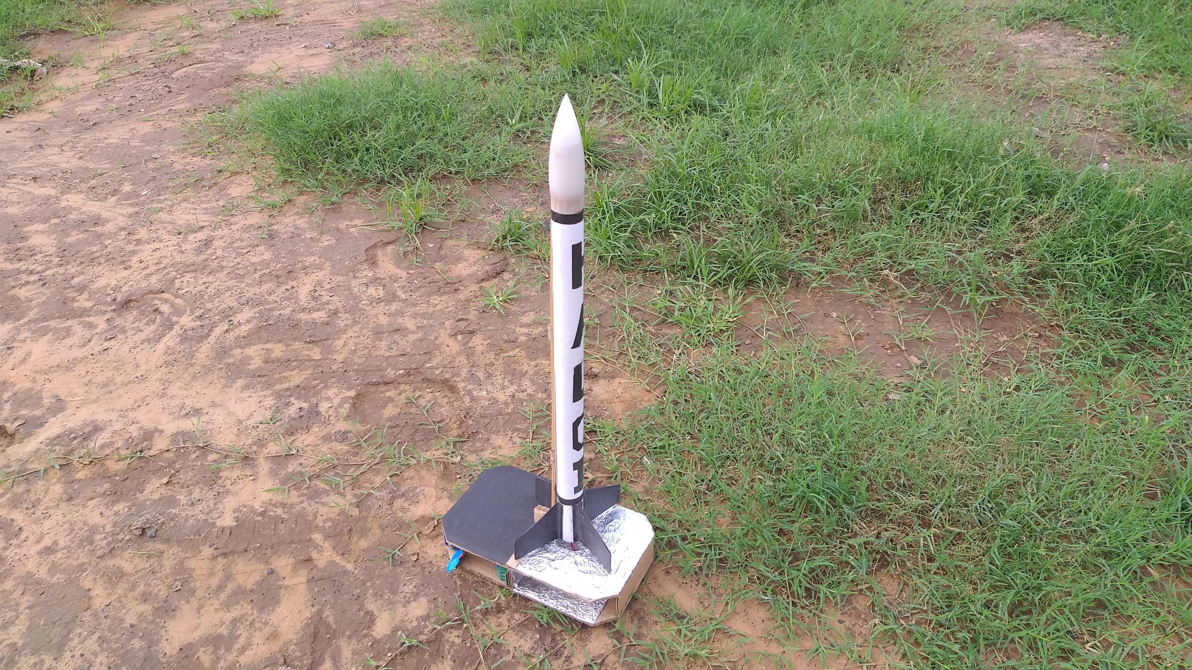
Before we start cutting cardboard and soldering wires, here's the 30,000-foot view of what's actually happening inside Launchpad — so the wiring and code make sense later instead of feeling like magic.
The ESP32 does three jobs at once:
- It creates its own WiFi network. No router, no internet connection needed — the ESP32 runs in Access Point mode, broadcasting a network called Launchpad. Your phone connects directly to it, the same way you'd connect to any WiFi hotspot.
- It hosts a web page. Once connected, browsing to the ESP32's address loads a small web app running entirely off the board itself — the safety checklist, the arm screen, the hold-to-launch button, the countdown. All of it is served by the ESP32, no external hosting involved.
- It runs the safety logic. This is the part that matters most: the state of the launch pad — whether it's disarmed, armed, counting down, or firing — lives on the ESP32 itself, not in your phone's browser. Your phone just sends simple requests ("arm," "launch") and polls the ESP32 every fraction of a second to see what state it's in. This matters because it means closing the browser tab, your phone locking, or even a bug in the web page can't accidentally leave the pad armed or trigger a launch. The ESP32 is always the one actually in charge.
The relay is the muscle. The ESP32 itself can't handle the current needed to fire an igniter — and shouldn't, for isolation reasons. Instead, it sends a small signal to the relay module, which acts like a remote-controlled switch, completing a separate high-current circuit (igniter + battery) only for the ~2 seconds it needs to fire.
The buzzer is the voice. It beeps steadily through the 10-second countdown, speeding up in the final few seconds, then holds a solid tone at the moment of ignition — giving everyone nearby an audible cue, not just a visual one on someone's phone screen.
The foil-lined enclosure is the armor. Since the ignition chamber deals with heat and a small pyrotechnic event, the cardboard shell is lined with crinkled aluminum foil — intentionally left textured rather than smooth, since the extra surface area helps it dissipate and reflect heat more effectively than a flat sheet would.
Put together: checklist → arm → hold → countdown → relay fires → done. All of it running on a $5 microcontroller sitting in a cardboard box you probably already have the materials for.
Marking and Cutting the Enclosure
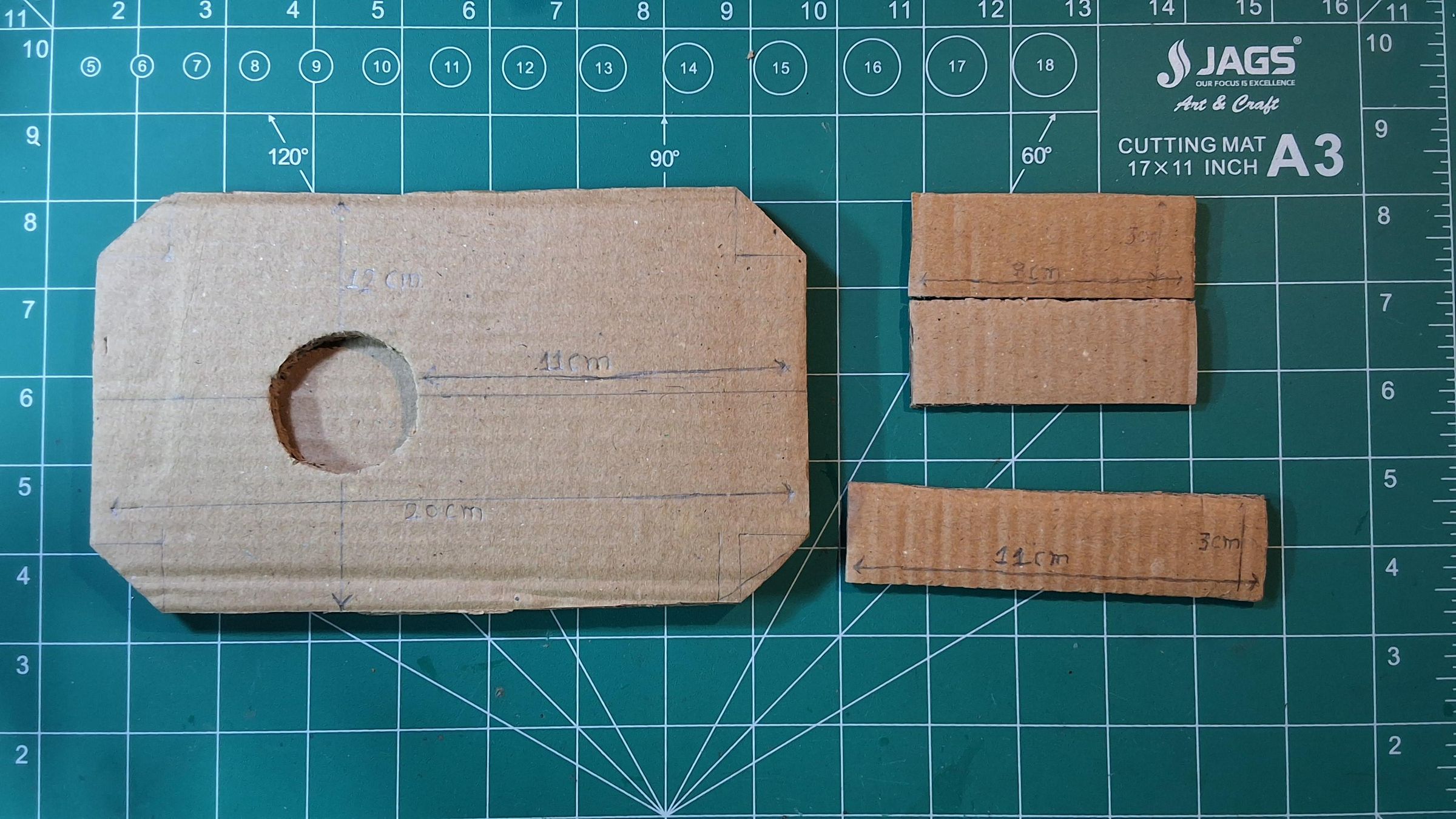
With the electronics side of things clear, let's build the box that holds it all.
Step 1: Mark out the main panel.
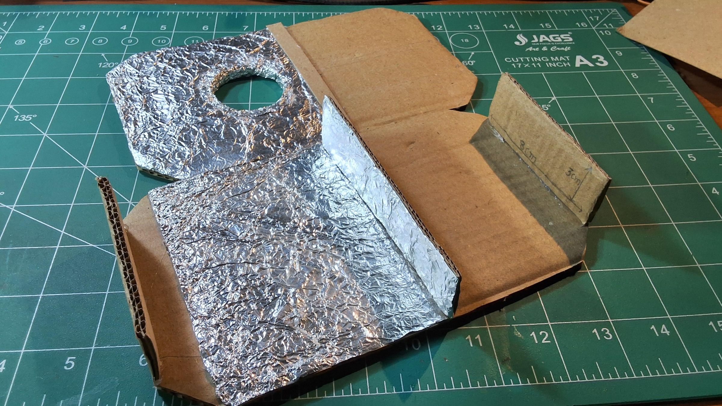
On a sheet of corrugated cardboard, mark a rectangle roughly 20 cm long and 12 cm tall. This forms the main body panel of the enclosure — the section that will house the electronics on one side and the ignition chamber on the other.
Step 2: Mark the ignition hole.
About 11 cm in from one edge, mark the center point for a circular hole — this is where the igniter/nozzle end of the rocket motor sits, and where the heat and flame actually vent through. Trace and cut this circle out cleanly with a craft knife; take it slow here, since a rough edge on this hole is the one place on the whole build where clean cutting actually matters for airflow and heat venting.
Step 3: Trim the corners.
Notice the angled corner cuts in the reference photo rather than sharp 90° corners — this isn't just cosmetic. Angled corners make the box noticeably more rigid once assembled and give you cleaner edges to glue against later.
Step 4: Cut the side strips.
Alongside the main panel, cut a few narrower strips — in this build, roughly 8 cm × 3 cm and 11 cm × 3 cm. These become the connecting side walls that give the enclosure its depth, joining the front and back panels together into a proper box rather than a flat sheet.
Step 5: Cut a matching second panel.
You'll need a second panel with the same footprint as the first (mirrored, if your enclosure has two symmetrical halves like this build does) — one half houses the electronics bay, the other houses the ignition chamber with the vented hole.
A tip that saved me some frustration: mark everything in pencil first and dry-fit the pieces together before cutting the final shapes. Cardboard doesn't forgive measuring mistakes the way you'd hope.
Lining the Enclosure With Heat-Shield Foil
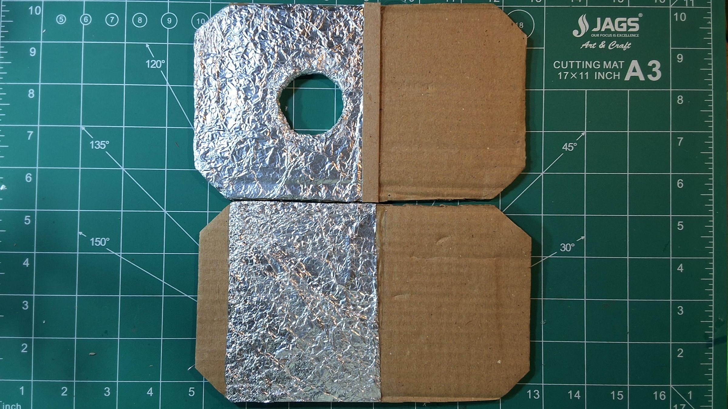
With the panels cut, the next step is protecting the cardboard from the heat it's about to be exposed to near the ignition chamber.
Step 1: Cut foil sheets to match your panels.
Tear off at least 2 to 4 pieces of standard kitchen aluminum foil, roughly matching the size of the panel you're covering, with a little extra overhang on each edge to fold over and secure.
Step 2: Crinkle the foil before applying it — on purpose.
This part looks like a mistake if you don't know why it's there, so it's worth calling out clearly: don't smooth the foil flat. Scrunch it up loosely first, then flatten it back out just enough to work with. That crinkled, uneven texture you see in the photos isn't sloppy application — it's intentional. A crinkled surface has significantly more actual surface area than a flat sheet the same size, which means better heat dissipation and reflection around the ignition chamber. A smooth, flat foil layer would look tidier, but it'd genuinely perform worse at the one job this layer has.
Step 3: Glue the foil down.
Apply glue to the cardboard panel (not the foil) and press the crinkled foil on top and stack on top of each other( the more the layers, the better it protects the base from the heat), working from the center outward to avoid trapping large air bubbles. Fold the overhanging edges around the sides of the panel and glue those down too, so there's no exposed cardboard edge facing the ignition chamber.
Step 4: Cut the vent hole through the foil.
For the panel with the ignition vent hole already cut in step 5 of the previous section, carefully cut the foil away from that opening too — you want the hole fully clear, not covered over.
Step 5: Repeat for both panels facing the ignition chamber.
Both inner faces that will be exposed to heat get this treatment. The electronics bay side doesn't need foil, since it's isolated from the ignition chamber.
One thing to flag honestly: this foil layer is a heat shield and reflector for a hobby-scale ignition source, not a substitute for keeping proper clearance from the actual motor exhaust. It protects the box; it doesn't make the box fireproof.
Wiring the Electronics
.png)
With the enclosure ready, let's wire up the electronics before mounting them inside.
Components going in:
- ESP32 Dev Board
- 1-Channel Relay Module
- Active Buzzer
- 9V Battery + Snap Connector
- Jumper wires
- Electric matches or igniters
A couple of things worth calling out explicitly:
- Keep the igniter circuit physically separate from the ESP32's own power. The relay's COM/NO contacts should only ever be in series with the igniter and its own battery — never tied back into the ESP32's power rails. This is what actually keeps the "logic side" and the "ignition side" electrically isolated.
- Double-check your relay's trigger polarity before wiring it in permanently. Most inexpensive 1-channel relay modules are active-LOW (they switch on when the signal pin goes LOW, not HIGH) — this tripped me up during testing too. The code accounts for this with a single RELAY_ACTIVE_HIGH setting, but it's worth verifying with a multimeter or LED test before your first real bench test.
- Route wires with some slack, especially around the relay and buzzer — you'll be tucking all of this into a fairly tight cardboard bay in the next step, and taut wires make that fiddlier than it needs to be.
Mounting Electronics Inside the Enclosure
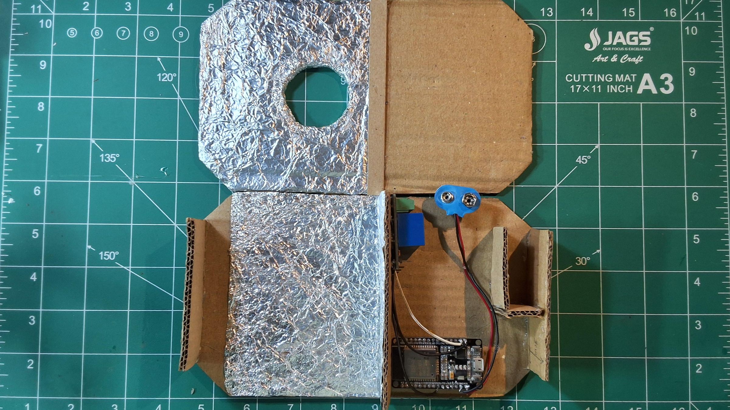
With everything wired and tested loose on the bench, it's time to actually tuck it into the enclosure.
Step 1: Dry-fit before gluing anything.
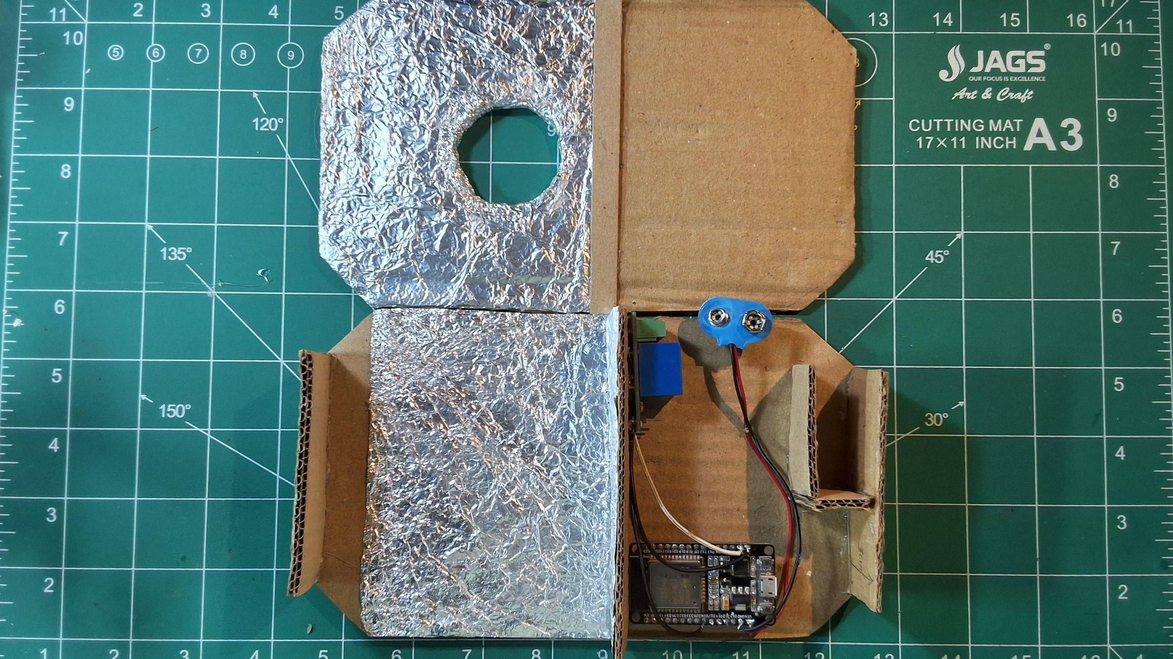
Place the ESP32, relay, and battery snap into the electronics bay side of the enclosure (the non-foil half) without securing anything yet. Check that the USB port on the ESP32 is still accessible from an edge or opening — you'll need it later for flashing code and for any future re-uploads, and there's nothing worse than realizing it's sealed in after the glue dries.
Step 2: Mount the relay first.
The relay sits near the top of the bay in this build, close to where the wires cross over toward the ignition chamber side. Secure it with a small dab of hot glue on the underside of the module — enough to hold it in place, without covering the screw terminals you'll need for the igniter-side wiring later.
Step 3: Mount the ESP32.
Place the ESP32 flat along the base of the bay, USB port facing an open edge. A couple of small glue points at the corners of the board are enough — avoid gluing over the pins or the boot/reset buttons in case you need to access them.
Step 4: Secure the 9V battery snap.
The battery itself doesn't need to be permanently fixed (it's nice to be able to swap it out), but the snap connector's wires should be anchored so they don't tug on the ESP32's pins. A small cardboard tab or loop of tape works well here, as shown in the reference photo.
Step 5: Route wires toward the ignition chamber side.
The relay's COM/NO leads need to reach through to the igniter circuit on the other side of the enclosure. Route them along the inside wall rather than straight across the middle, keeping them clear of the foil-lined vent hole.
A small but genuinely useful habit at this stage: power it on before closing anything up, and confirm the WiFi network shows up on your phone and the web page loads. It's a lot easier to fix a loose connection now than after the enclosure is glued shut.
Building the Igniter/Launch Rod Mount
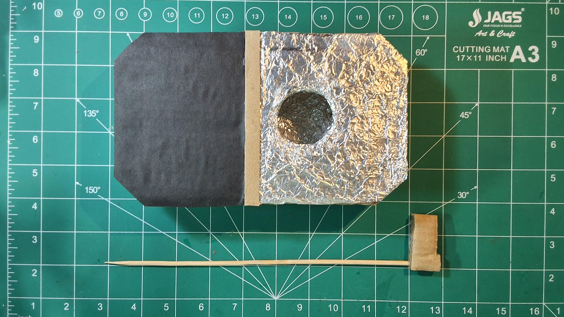
This small piece is easy to overlook, but it's what actually holds your rocket upright and steady on the pad — everything else in this build only matters if the rocket itself is positioned correctly to launch straight.
Step 1: Cut a small cardboard clip block.
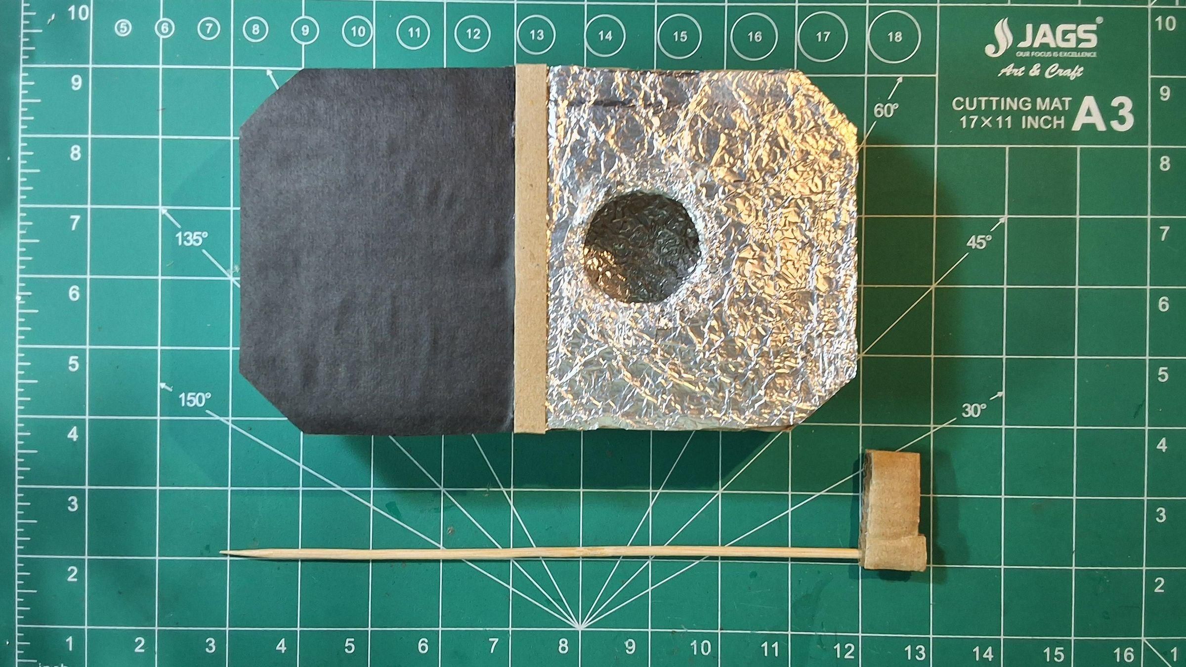
From scrap cardboard, cut a small rectangular block — in this build, roughly the size of a large postage stamp folded over itself for extra thickness. This becomes the base that grips the launch rod.
Step 2: Pierce it with the launch rod.
Push a bamboo skewer straight through the center of the cardboard block, so it sits perpendicular to the block and holds firm by friction alone. This skewer acts as the launch rod — the same role a metal launch rod plays in commercial pads, guiding the rocket straight up during the first critical inches of flight before fins alone can stabilize it.
Step 3: Check the fit against your rocket's launch lug.
Most model rockets have a small launch lug (a thin tube glued to the body) that the rod slides through. Test-fit your skewer through this lug before going further — you want a snug slide, not a tight jam or a loose wobble.
Step 3.5: Size the rod length to your rocket, not to a fixed measurement.
The skewer length isn't a one-size-fits-all number — it should scale with your rocket. As a rough rule of thumb, the rod needs to stay engaged with the launch lug for long enough to keep the rocket stable until it's built up enough speed for its fins to take over (generally until it's traveling around 15+ m/s). In practice, that means:
- Small/light rockets can get away with a shorter rod, roughly matching the rocket's own body length.
- Larger or heavier rockets need a proportionally longer rod — often 1.5–2× the rocket's length — since they need more distance to build up stabilizing speed before leaving the rod.
A rod that's too short lets the rocket wobble off in an unpredictable direction right at launch; too long isn't dangerous, just unnecessary. When in doubt, size up rather than down.
Step 4: Position the mount relative to the ignition chamber.
The base of the skewer should sit close to, and centered on, the vent hole cut into the foil-lined panel — this is what lines the rocket motor's nozzle up with the ignition chamber below it.
One honest note here: this is a lightweight, low-cost launch rod solution that works well for small/light model rockets. If you're flying anything larger or heavier, a proper metal launch rod (even just a length of steel rod) will give you better rigidity and heat resistance than a bamboo skewer.
Assembling the Enclosure
With the electronics mounted and the launch rod ready, it's time to close everything up into its final form.
Step 1: Dry-fit both halves one more time.
Before any glue goes down permanently, bring the electronics bay half and the foil-lined ignition chamber half together and check the fit. Confirm the vent hole lines up where you expect, the relay's igniter-side leads reach comfortably across, and nothing is under tension.
Step 2: Glue the side strips into place first.
Using the narrower strips cut earlier (the ~8 cm and ~11 cm pieces), glue these along the edges to join the front and back panels into an actual box shape rather than two flat sheets. Work one edge at a time, holding each strip in place for a few seconds until the glue grabs.
Step 3: Join the two panel halves.
Bring the electronics bay and the ignition chamber halves together along their shared edge, gluing them into a single continuous enclosure. Keep the relay's igniter leads accessible right up until this point — you don't want them trapped or pinched inside a seam.
Step 4: Leave access points open.
Before fully sealing anything, double check three things are still reachable from the outside:
- The ESP32's USB port (for code updates)
- The 9V battery (for swapping when it runs low)
- The relay's COM/NO terminals (for connecting the igniter circuit fresh each launch)
Step 5: Reinforce the seams.
Run a bead of glue along any remaining open seams for rigidity, especially around the corners cut at an angle earlier — those joints take the most stress when the enclosure is handled or set down on uneven ground.
At this point, you should be holding something that actually looks like a launch pad rather than a pile of cardboard and wires — a good moment to pause, power it on one more time, and confirm everything still boots up correctly after all that handling.
Uploading the Code
With the hardware fully assembled, the last step is flashing the ESP32 with the firmware that runs the whole show.
Step 1: Install the Arduino IDE and ESP32 board support.
If you haven't already, install the Arduino IDE, then add ESP32 board support via the Boards Manager (search "esp32" and install the Espressif package). No external libraries are needed beyond what ships with the ESP32 core — WiFi.h and WebServer.h are both built in.
Step 2: Open the Launchpad sketch and set your board.
Download Launchpad code from my github and open Launchpad.ino, then under Tools → Board, select your specific ESP32 dev board variant.
Step 3: Check the configuration constants at the top of the file.
A few values are worth reviewing before your first upload:
Set RELAY_ACTIVE_HIGH to match whatever you confirmed during bench testing in the wiring step, and change the WiFi password to something of your own.
Step 4: Upload.
Connect the ESP32 via USB, select the correct port under Tools → Port, and hit Upload. Once it finishes, open the Serial Monitor at 115200 baud — you should see the AP's IP address printed, confirming it booted correctly.
Step 5: Connect and verify.
From your phone, join the Launchpad WiFi network and browse to the printed IP address. If the safety checklist page loads, you're good to move on to actually using it.
The full sketch is attached at the end of this Instructable — here's a snippet of the core state machine for reference:
Step 6: Troubleshooting — relay stays on by default / fires backwards.
If you power on the pad and the relay is energized immediately at idle (and only turns off during what should be the firing pulse), your relay module is wired with opposite polarity to what the code expects. This is a common gotcha — most inexpensive 1-channel relay modules are active-LOW rather than active-HIGH, and it's easy to assume the opposite.
The fix is a single line. Find this constant near the top of the sketch:
and flip it to:
Re-upload, then verify with an LED (never a real igniter) that the relay is off at idle and only switches on during the ~2 second firing pulse. Everything else in the code already reads from this one constant, so nothing else needs to change.
Using the Web Interface
With the firmware flashed and the relay behavior confirmed correct, here's how the actual launch flow works from the user's side.
Step 1: Connect to the pad.
Join the Launchpad WiFi network from your phone and browse to the ESP32's IP address (shown in the Serial Monitor on first boot, or printed on the enclosure for quick reference).
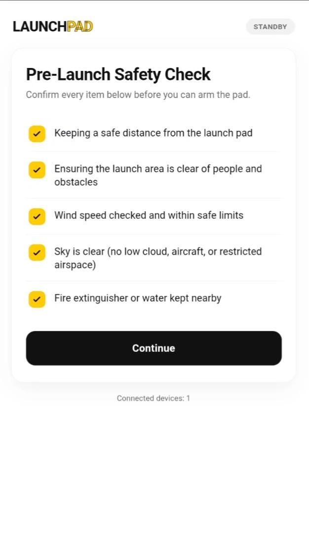
Step 2: Work through the safety checklist.
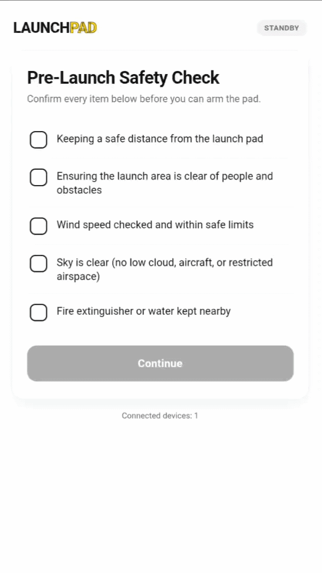
The first screen presents the five safety confirmations — safe distance, clear area, wind speed, clear sky, extinguisher/water nearby. Each is a large, tappable card rather than a tiny checkbox, since this is meant to be used outdoors, often in bright sunlight, sometimes with gloves on. All five must be checked before Continue becomes active.
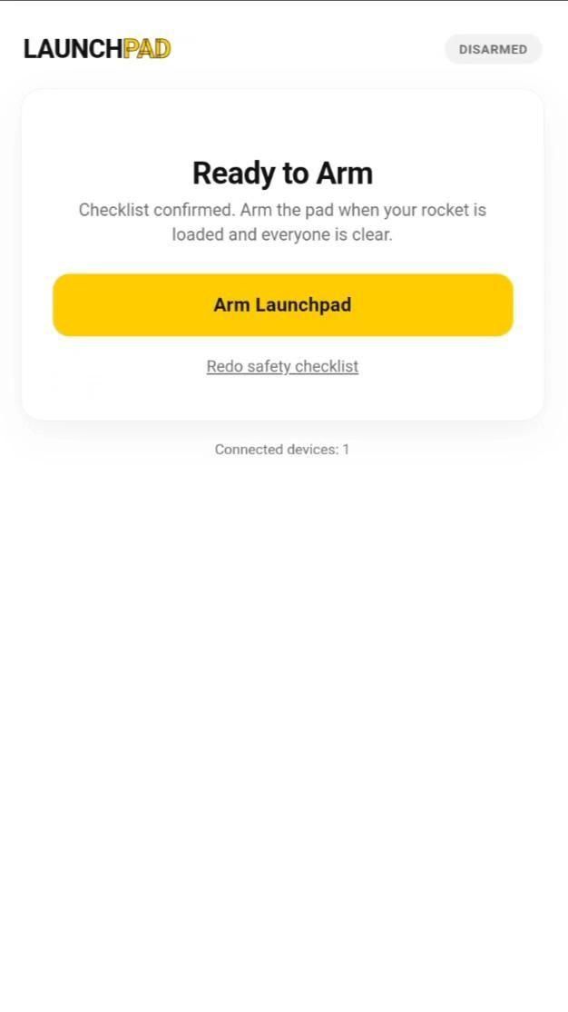
Step 3: Arm the pad.
Once past the checklist, the Arm Launchpad screen appears. Tapping this is a deliberate, single action — the pad is now live, and the interface switches to a bold "Armed" indicator so there's no ambiguity about its state.
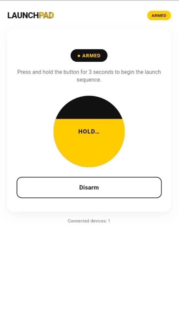
Step 4: Hold to launch.
The armed screen shows a large circular HOLD button. Pressing and holding it fills the button with color over 3 seconds — releasing early cancels the action entirely, so there's no way to trigger a launch with an accidental tap.
Step 5: Countdown.
Once the hold completes, the countdown screen takes over automatically — a large numeric readout counting down from 10, paired with an escalating buzzer pattern that speeds up in the final few seconds.
Step 6: Ignition and auto-reset.
When the countdown hits zero, the relay fires for its ~2 second pulse, the interface shows an ignition confirmation, and after a short cooldown the pad automatically resets all the way back to the safety checklist — ready for the next flier to go through the same process from scratch.
One behavior worth calling out on this screen specifically: if your phone drops off the pad's WiFi at any point while armed or mid-countdown, the pad disarms itself immediately — no lingering armed state waiting for a phone to reconnect.
Bench Testing the Relay & Buzzer
Before this pad ever sees a real motor, it's worth properly exercising the electronics end-to-end — with nothing dangerous connected yet.
Step 1: Swap the igniter for an LED (or nothing at all).
Instead of wiring a real igniter across the relay's COM/NO terminals, connect a simple LED with an appropriate resistor, or just leave the terminals open and listen for the relay's audible click. Either way, you get a clear, safe signal of exactly when the relay switches.
Step 2: Run through the full web UI flow.
Go through the entire sequence as an end user would — checklist, arm, 3-second hold, 10-second countdown — and watch/listen for three things:
- The buzzer beeps steadily through the countdown and audibly speeds up in the final few seconds
- The relay (LED or click) stays off the entire time, right up until the countdown hits zero
- The relay fires for roughly 2 seconds at ignition, then cleanly turns back off
Step 3: Test the disconnect safety behavior.
Arm the pad, then turn off WiFi on your phone (or walk out of range) before starting the hold. Reconnect a few seconds later and confirm the pad has already dropped back to "Ready" / disarmed on its own — this is the one safety behavior you really don't want to discover doesn't work in the field.
Step 4: Test the abort-mid-countdown behavior the same way.
If your build includes a way to disconnect mid-countdown, confirm the relay never fires and the buzzer stops when the connection drops. This is the scenario that matters most, so it's worth testing deliberately rather than assuming it works because the disarm test passed.
Every electrical and logical piece of the system was bench-tested exactly as described above before any real igniter was ever connected — the results of that live launch are in the next section.
The Launch
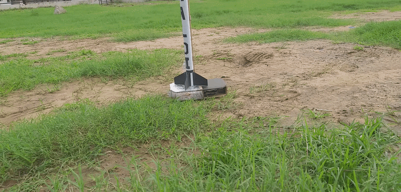
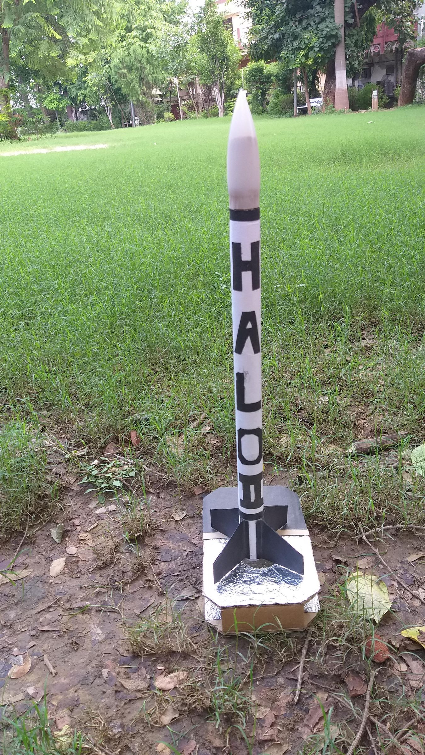
With the electronics fully bench-tested and the rain finally clearing, it was time to actually fly this thing.
Step 1: Final pre-flight checks.
Before loading a real motor and igniter, one last physical check: relay polarity confirmed correct, launch rod length matched to the rocket being flown (see the sizing note back in the launch rod mount step), and the enclosure's vent hole clear of any obstruction.
Step 2: Load the rocket.
Slide the rocket's launch lug onto the skewer, seat the motor with a fresh igniter, and connect the igniter leads to the relay's COM/NO terminals — the same terminals that were just an LED during bench testing, now doing the real job.
Step 3: Move to a safe distance and connect.
Walk well clear of the pad, join the Launchpad WiFi network, and open the web interface.
Step 4: Run the full sequence, for real this time.
Checklist, arm, 3-second hold, 10-second countdown — the exact same flow tested on the bench, except this time the relay firing means something happens.
Step 5: Ignition.
Watching the countdown hit zero and actually seeing the rocket leave the pad — rather than an LED blink — was honestly the best part of this whole build. Everything that got tested piece by piece over the previous weeks came together in about four seconds.
Final Thoughts & Next Steps
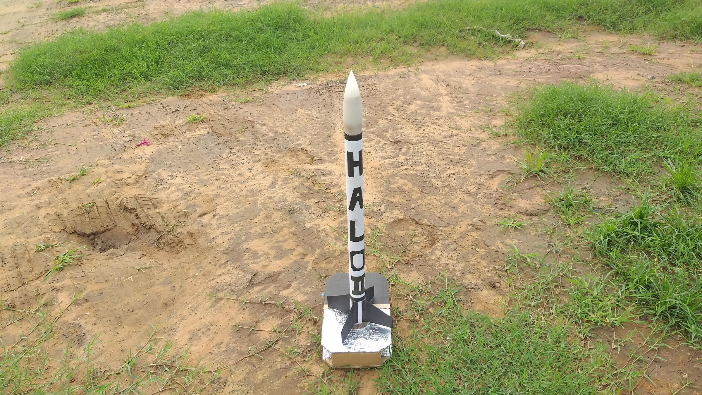
Building Launchpad turned out to be a good reminder that the "boring" part of a hobby — safety, reliability, not having to stand next to a live igniter — can also be the most satisfying thing to actually engineer. The rocket itself is the fun part everyone sees; the pad is what makes that fun part safe enough to enjoy without a knot in your stomach.
A few things I'd look at next, if you're building your own and want to take it further:
- A hard STOP/RESET button in the UI to abort mid-countdown on demand, not just on disconnect
- mDNS support (launchpad.local) so you're not hunting for an IP address in the Serial Monitor every time
- A status LED on the enclosure itself for at-a-glance armed/disarmed state, even without a phone in hand
- A proper metal launch rod for anyone flying larger rockets than the lightweight ones this bamboo-skewer version was built for
- And, obviously, an actual launch — this pad is bench-proven and just waiting on a dry afternoon
If there's one thing I'd want someone building their own Launchpad to take away, it's this: your backyard doesn't need a big renovation to become a better space to build and play in. Sometimes it just needs a cardboard box, a $5 microcontroller, and an excuse to get a little more deliberate about how you do the fun, slightly-dangerous things you were already doing anyway.
Full source code is attached here and above. If you build your own, I'd genuinely love to see how it turns out.