Learning About Engineering With CAD and Arduino With an Autonomous Car
2147 Views, 18 Favorites, 0 Comments
Learning About Engineering With CAD and Arduino With an Autonomous Car


Project Overview
This project-based course is based on using Fusion 360 to create designs for laser cutting and 3D printing parts for a small car. Students will learn about designing around the tools they have available, while being creative whenever any hiccups may happen.
This project can take anywhere from 1-2 weeks for students to complete (about 8 hours of work). There are some optional ways to build on the course to make the project last longer, such as making students add sensors and use sensor data for control.
Project Philosophy
I am a big believer in learning by trying and failing and trying again. In this way, this Instructable is meant to guide a teacher who wants to help their students do such a workshop, while also allowing an individual student to be able to create such a project in their very own home, with alternatives that can be done if there is not access to a laser cutter or 3D printer.
As someone who has make items out of the most random scrap parts, I encourage students to attempt to design around interesting parts. If they find something that they can get work (for example, I've seen a student attach a computer fan to their robot), then their creativity should be encouraged.
Engineering is all about experimenting, and this workshop hopes to encourage that by giving the basics, while also leaving lots of room for creativity, whether it be in CAD, engineering, building, programming, or critical thinking.
Previous Experience
This course can be taken by students from any level of experience. It may take longer for students who have not done CAD or programming before, but they should be able to learn the basics by learning in practice.
Learning Objectives
Students will practice many facets of engineering, and will learn more about CAD, electronics, and programming, and the combination of all of these to make an autonomous car.
Students will have to get creative to make deadlines or to solve different challenges.
Course Challenge (Optional)
From my experience, students love a competition. If the schedule allows for it, I like to give students an objective to work towards (or multiple), for example, navigating a maze with their robot, or making their robot be able to traverse water.
Supplies

Tools needed:
3D Printer (optional)
Laser Cutter (optional, can use a normal printer instead)
Materials Needed:
Arduino Uno
DC Motors
Breadboards
Battery Pack and batteries
Wires
PNP transistor or motor controller
Servo (optional)
Sensors (optional)
Laser cuttable material
3D Printer filament
Adhesives
Screws
Take Some Measurements


A lot of parts are very helpful to have in CAD, there are two ways to design around the parts you already have. You can search the web and upload a file of the part, or you can approximate the geometry of the part after taking some careful measurements. In my case I approximated the size of the servo to a rectangular prism.
Measure how much space your parts will take up and design around that (make sure to have some tolerances though!)
Design

Brainstorm and sketch
Have students make some simple sketches of where they want their parts. Let them hold the parts in their hands and try to orientate the things that will have to go on the robot in a way that they like.
Parts that will go on the robot: Arduino UNO, battery pack, 2 motors, breadboard, servo, wheels.
Separate your design
Have students separate the design into multiple parts, such as a robot base, robot walls, motor mounts, etc.
Basics of CAD

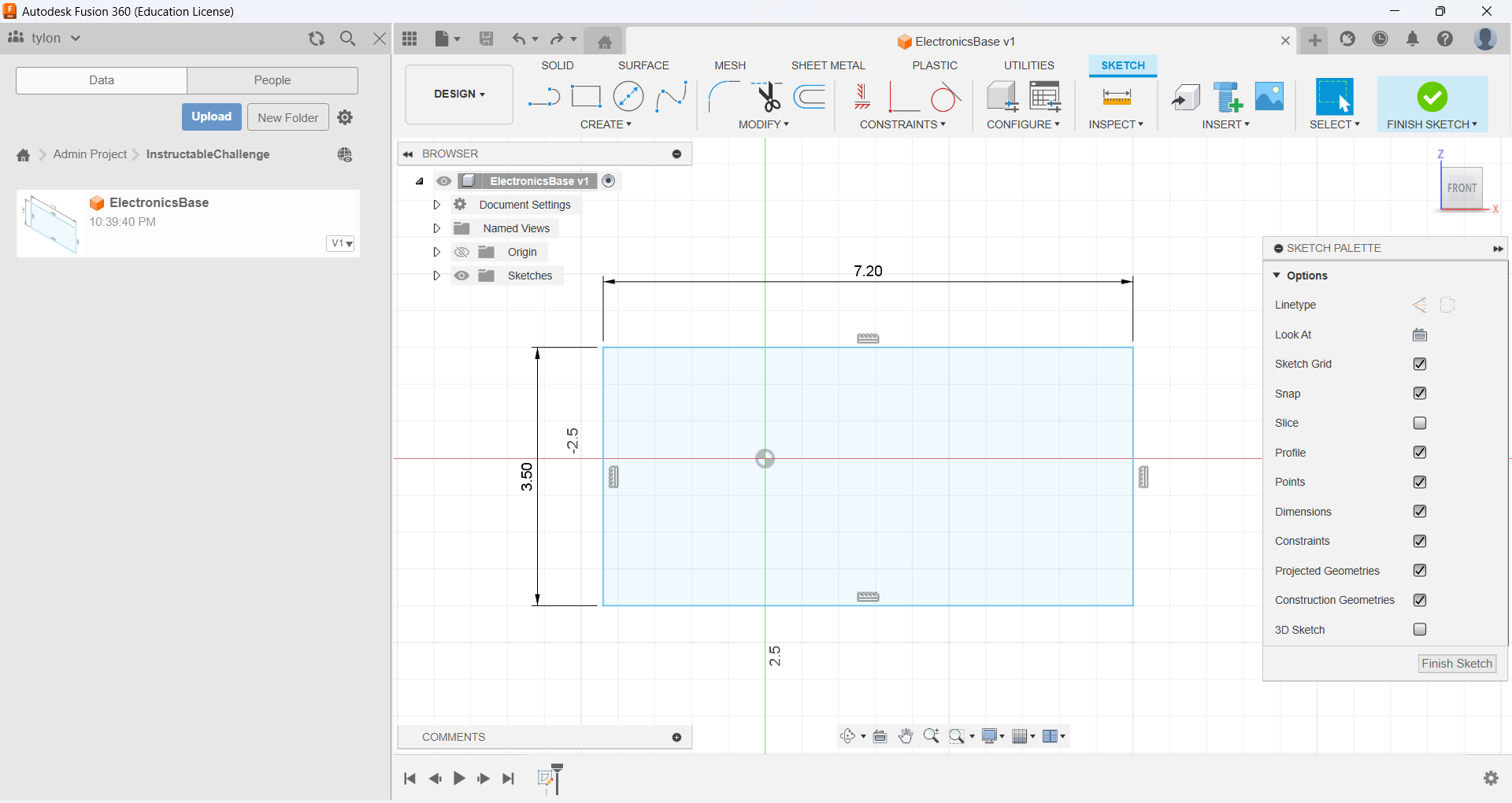

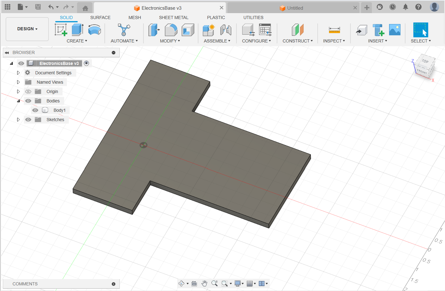
After students have a good idea of what parts they need to make, have them start by designing the part that most parts will reference. In this case it is the baseplate.
Have an idea of what you have
Make sure that students have a good idea of what the part will be made out of, or what manufacturing method. Designing for laser cutting is very different then designing for laser cutting. In general, laser-cutting is fast and precise and is good for large pieces, but it can only cut two dimensional simple objects. 3D printing is slower but has high precision and can make nearly any part in plastic.
Give students a good idea of what methods of connections they can use. In my case I used hot glue and screws and nuts. Being creative with duct tape is also a valid method that I've seen some do, for example, a hinge or flap mechanism can be done.
Simple designing tips
The general formula for designing something in Fusion 360 is to create a sketch (top left corner when starting a new project), draw out a shape using the various sketch tools, and then extrude the part. It is good to extrude to a thickness equal to the material you want to be using. In my case I used 1/4'' thick plywood, so I extruded the part 0.25 inches.
Downloads
CAD for Complex Parts


Some parts may be difficult to CAD around. I designed motor mounts around the part, but I had to ensure that they were able to work in real world, so it was important to reference the relevant parts.
A useful tool is while in a sketch to press P, which allows you to project the geometry of a part onto your sketch. Think sort of like casting a shadow of a part onto a picture.
Have students design complex parts and assist them if it might not be feasible to 3D print, teach them some good things to keep in mind such as to minimize overhangs and to separate out pieces.
Make sure to have students visualize how they would assemble/attach the part to an object as well. For example, if the motor mount designed was not split in half, it would be difficult to fit the motor into the part. The solution I took was to split the part in half, but a possible solution may have been to remove some material above the location of the axle, so it can be placed from the top.
Assemble Models

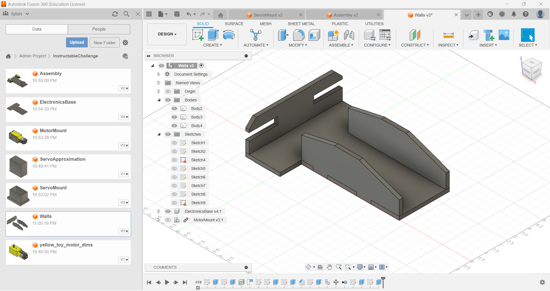
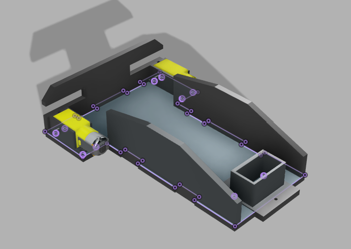


Test fits
It is important to assemble, and test fit together parts in CAD. If there are any overlaps in models, that is an issue that means that some things have to be redesigned.
An assembly is also helpful for referencing other parts.
A useful tip is that when adding other parts, but you want to modify an added part based off of references in the current part, you can right click that part and 'break link', and you will be able to freely modify it afterwards.
A tip for moving parts is snapping together parts with the 'joint' tool in the assemble section of the tool bar. More easily, a part can be right clicked, and 'move/copy' can be selected to move parts around.
How do parts fit together?
Make sure you have a good idea of how parts will fit together once they are made in the real world. In my case, I created slots so that laser cut parts will be able to slot into each other, and in my motor mounts that I plan to 3D print, I added holes for screws to go through and will be tightened with nuts on the other side.
The base plate had to be modified to allow for these connections.
Iterate, Then Fabricate


Iterate
Make sure students go back and remake parts. As a teacher you can choose to do a design review, or have students review each other's designs and look for issues.
Some common design issues: Parts overlap, would not fit in real life. Parts fit in their final position but will be impossible to get to that position. Parts are unrealistic to fabricate. Parts do not have a planned way to fit onto the base or to another part.
Fabricate
This part can be done differently depending on the tools available.
For flat parts, a DXF file can be exported from a sketch. The easiest way to do this is to press P and project the entire geometry of the top face, then find it in the browser on the left and right click the sketch and export it as DXF.
A DXF can be used to laser cut parts. Alternatively, it can be printed on a normal printer, glued onto cardboard/foamcore, and be cut out with an X-acto knife.
An STL,STEP,3mf file can be exported from parts. If there are multiple parts in one sketch that you want to export, go to the browser and hide all components/bodies until just the one you want is visible, then export. Repeat for all parts. These parts will likely have to be 3D printed. If there is not access to one, make sure to tell students in advance so they can design around the cutting manufacturing method, and design strictly flat parts.
Assemble


Have students assemble their models. In my case, I found that I had an issue with the Servo motor, so I decided to hot glue a different Servo motor on instead. My wooden parts I also glued on into their respective joints, and I screwed the motor mounts into the plates.
Electronics


I used two PNP transistors as switches to control the motors. Essentially what they do is the left lead, and the right lead are not connected until the middle lead of the transistor is powered. It is powered via the Arduino.
The servo motor is connected with power, ground, and control to one of the data pins of the Arduino.
As a teacher, you can emphasize this part more in the course, for example, adding sensors, motor controllers, and more.
With this current setup, the motors only get around 5V of power, so they do not run very fast. The solution is to use higher voltage, such as a 9V power clip and have that power connected to the motors.
Programming
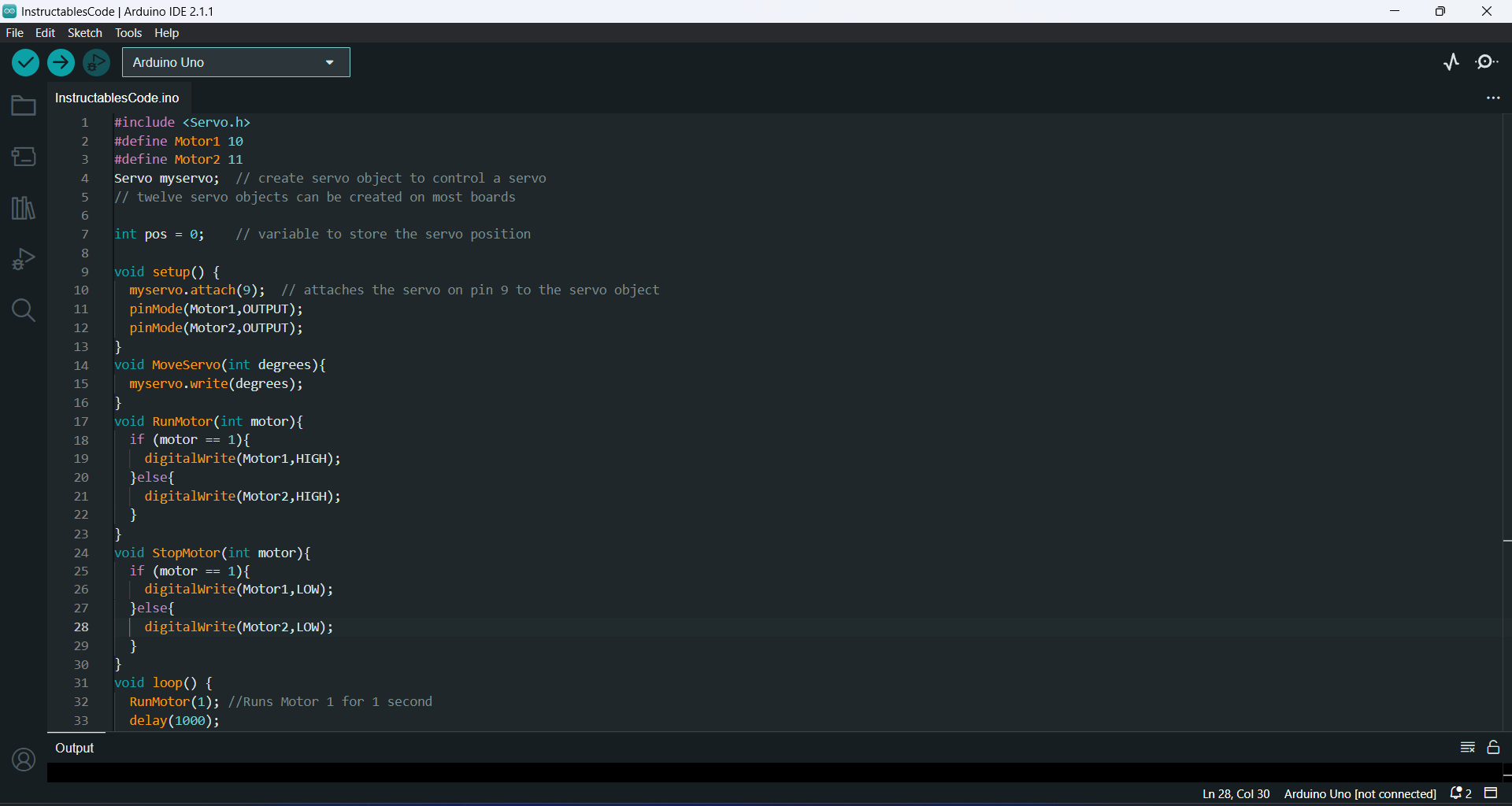
Programming for Arduino has two parts, the setup and the loop. I define pins 9,10,11 for controlling the servo, the first motor, and the second motor respectively.
Code Breakdown
I created some functions to more easily control the motors. When they are called, the signal is sent to the transistor, which closes the switch and allows for the motor to be powered. In this way, we are able to control the movement of the robot.
The servo can be rotated based on degrees, which I also created a function for.
In the loop, I have the robot perform an action, such as move a motor, delay(milliseconds) to have it perform that action for that amount of time. At the end of the loop, I have it delay for a very long time to essentially have the code run once.
As a teacher, this part can additionally be expanded upon, with some suggestions being a coding competition where students must have their robot traverse a course and perform various actions with their servo motor. If sensors were incorporated from the previous step, sensor information, such as from a distance sensor or encoder can help make the robot more interesting and autonomous.
At this point, you can stop at the coding section, or you can continue onto making the students a competition!