Learning Assembly With ATTINY85 Arduino Simulator - Part 1 (Blinking LED)
by EngineeringJourney in Circuits > Arduino
18 Views, 0 Favorites, 0 Comments
Learning Assembly With ATTINY85 Arduino Simulator - Part 1 (Blinking LED)

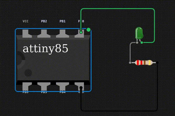
Learn assembly by doing and gain a deeper insight into the world of micro-controllers! We will be using the AVR instruction set and Velxio-- an online simulator that allows us to simulate ATtiny85 and interface them with external peripherals such as LEDs, displays and environmental sensors. This guide assumes the reader has basic Arduino programming background as we will be transitioning from Arduino to Assembly.
Supplies
Relevant links and documents:
1) Velxio: An online Arduino simulator (The first 3 compilations are free. After that, you will need to create an account, which you can sign in to using your Google account.).
2) 8-bit AVR® Instruction Set Manual : 8-bit AVR assembly language programming reference.
3) ATtiny85 Summary Datasheet: Quick reference guide for register mappings
4) ATTINY85 Complete Datasheet: Comprehensive technical documentation for the ATtiny85.
Setting Up the Online Simulator
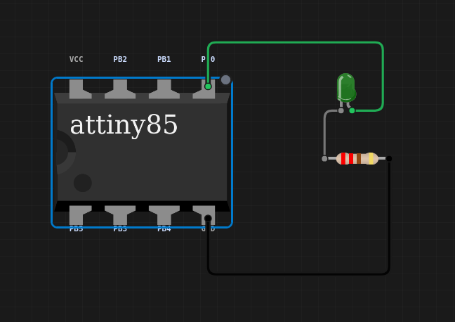
Setup a simple LED blink that is connected to the PB0 pin with a resistor on Velxio. Of course, we will start with the simple blink sketch that everyone is familiar with:
Compile and start the project, by pressing on the green arrow. Depending on the server load, it might take quite a bit of time but soon, you would get an led blinking.
Using Inline Assembly
Alright now for the fun part, we will start replacing Arduino with abit of Assembly Instructions. Let's start with the simplest with replacing pinMode():
Simply replace it with the following statement:
Re-run the simulation and the LED should still be blinking.
Understanding the Magic Numbers
Now, lets deconstruct the statement word by word, they could be broken down into two parts:
Inline assembly commands
- asm: Tells the Arduino compiler that the input to this function is a piece of assembly code (using __asm__ works too).
- volatile: Tells Arduino compiler not to remove/reorder the assembly statement.
Actual assembly code
- sbi: Set the bits in the register to be 1.
- 0x17: A hexadecimal register address (8-bit memory address) in the ATtiny85.
- 0: These are the target bits, bit 0 which refers to pin PB0.
Therefore, the assembly code can be simply read as "Set 1 to bit 0 of register 0x17." i.e. configure PB0 as an Output.
Blinking on Other Pins
_datadirection.png)
Above shows an image of the Data Direction Register address bits (page 64 of ATTINY85 Complete Datasheet), the memory address that is responsible for setting pin directions (like pinMode()). The mapping between the pins and the register address is pretty straight forward, bit0-PB0, bit1-PB1, bit2-PB2, ... etc.
Therefore, to blink on pin PB1, we need to set bit 1 to be 1.
Don't forget to change the rest of the code and the circuit too!
Try playing around and setting other bits, such as 3 and 4!
Replacing DigitalWrite
_dataregister.png)
Next, lets replace digitalWrite() with the corresponding assembly code. The snippet above shows the bit mapping of the Port B Data Register (0x18), which controls whether each corresponding pin is set to HIGH or LOW.
To set PB1 to HIGH, we simply use:
Instead of previously using register 0x17 (Port B Data Direction Register), now we use register 0x18 (Port B Data Register).
Subsequently, to set PB0 to LOW, we use the cbi (clear bit i/o) instruction instead:
Which can be read as, "Clear bit 1 of register 0x17."
Putting everything together and replacing digitalWrite(), the entire code should look like this:
Blinking Multiple LEDs
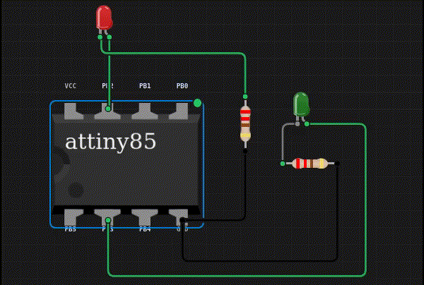
Now, lets try simultaneously blinking PB2 and PB3:
The blinking is abit erratic, but I guess that might be due to the limitations of the simulator.
Removing "magic Numbers" and Closing Notes
Its good practice to remove magic numbers (0x17, 0x18, etc..), and we should strive to be as expressive as possible when programming. Unfortunately, there is no easy way to do this when using inline assembly instructions.
Therefore something like this:
Which actually means "Set 1 to PB1 of register DDRB".
Can be expressively rewritten as:
Which looks pretty convulated with %0 and %1 are referring to the first (_SFR_IO_ADDR(DDRB)) and second (PB1) parameters. In fact, in a the pure assembly code the instruction would simply be:
However, since we are using an Arduino online simulator, there is no easy way around this. Regardless, we completed our first few assembly instructions—and there is much more to come!