Lifepod: a Self Contained, 24/7 Server
by twentyone21 in Circuits > Raspberry Pi
6353 Views, 74 Favorites, 0 Comments
Lifepod: a Self Contained, 24/7 Server
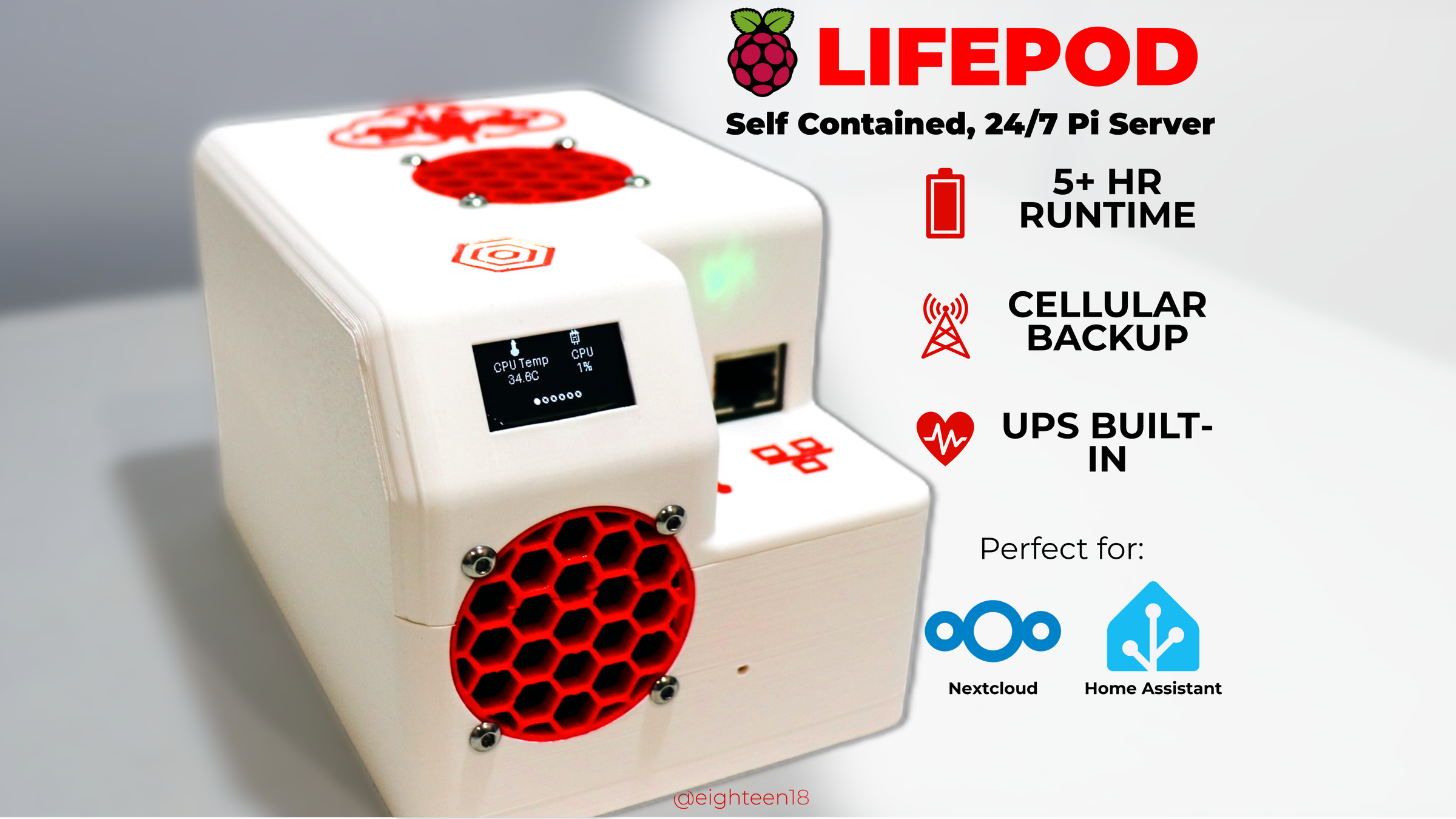
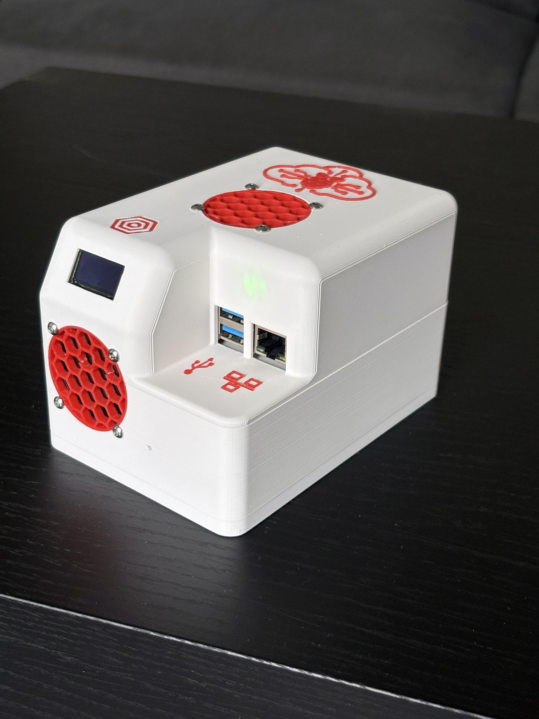
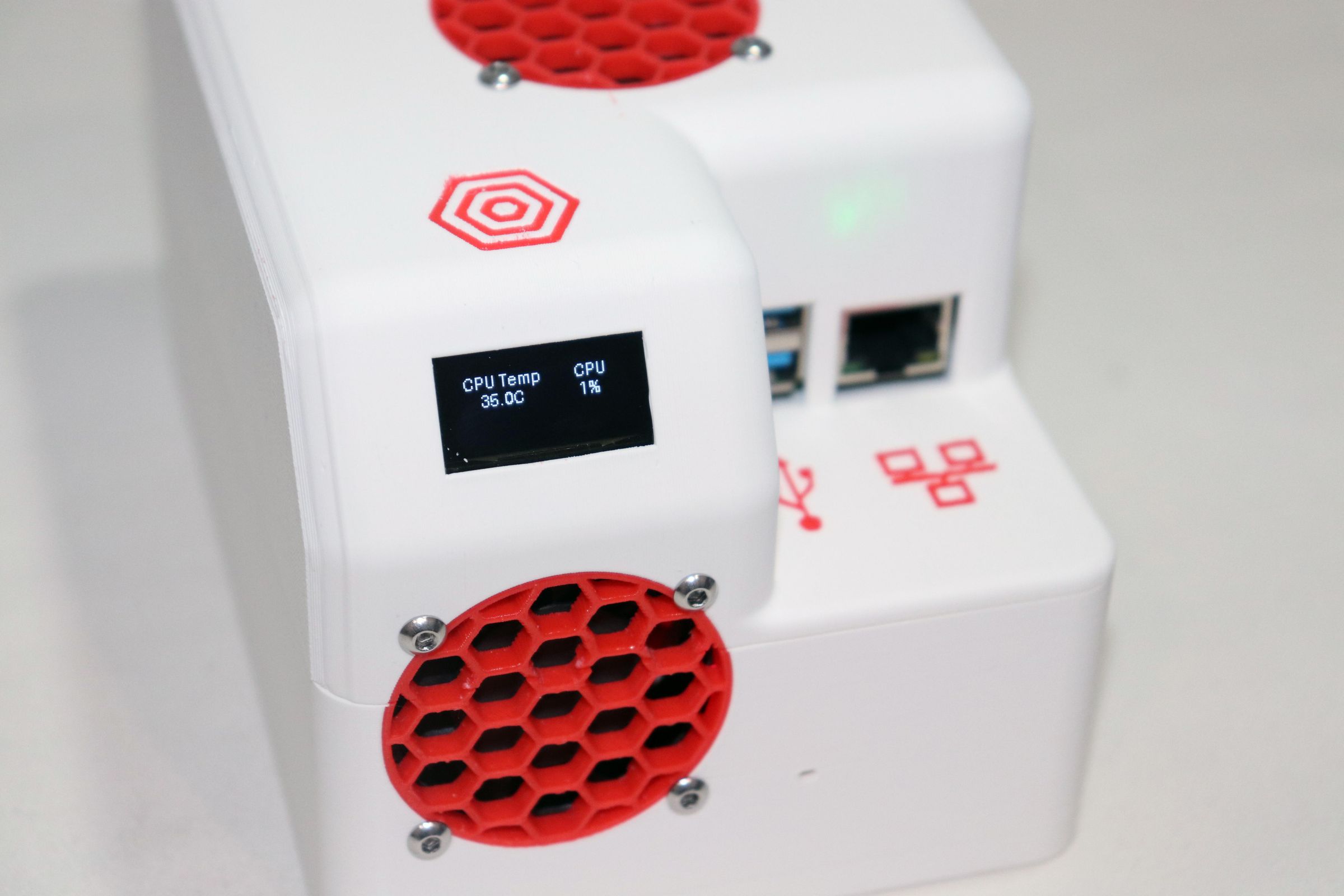
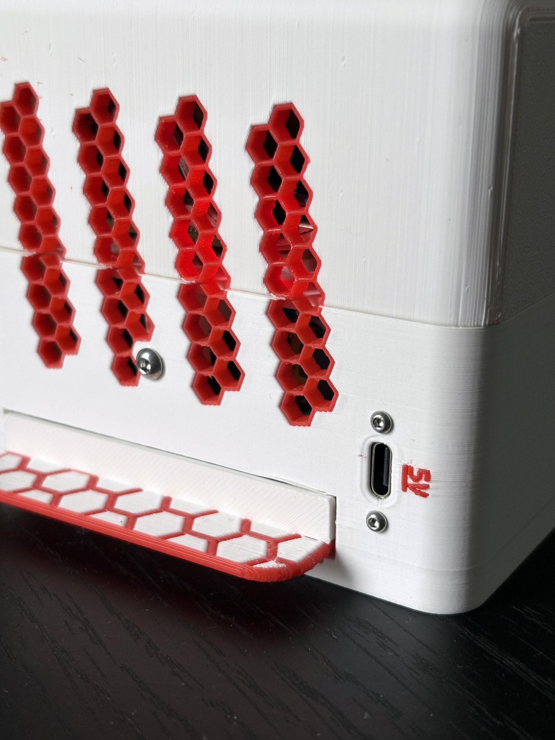
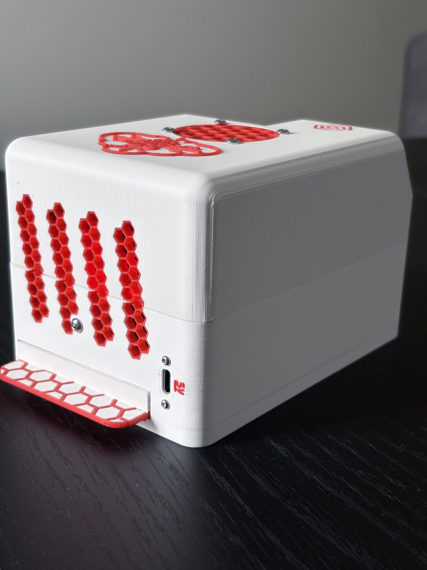
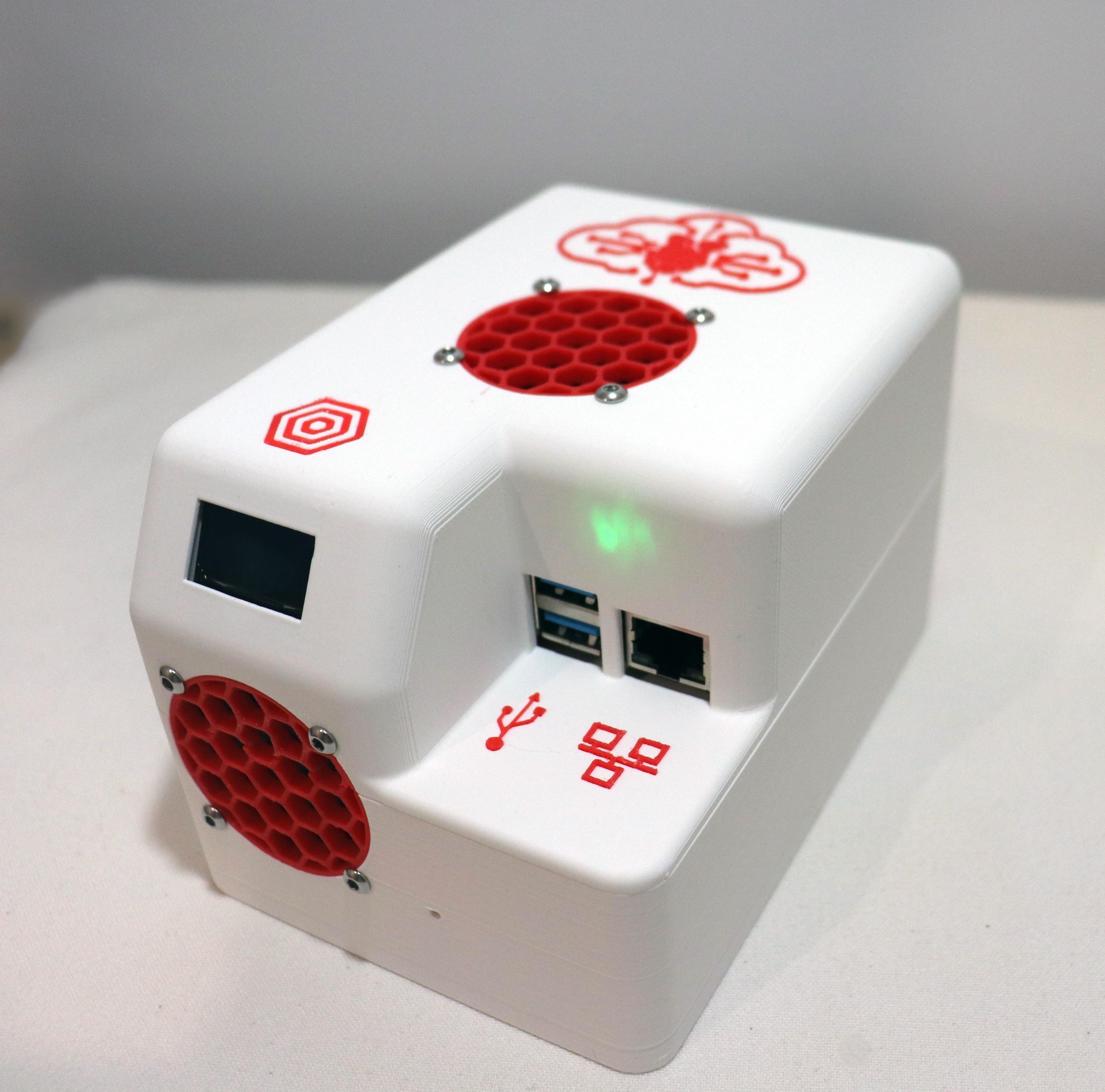
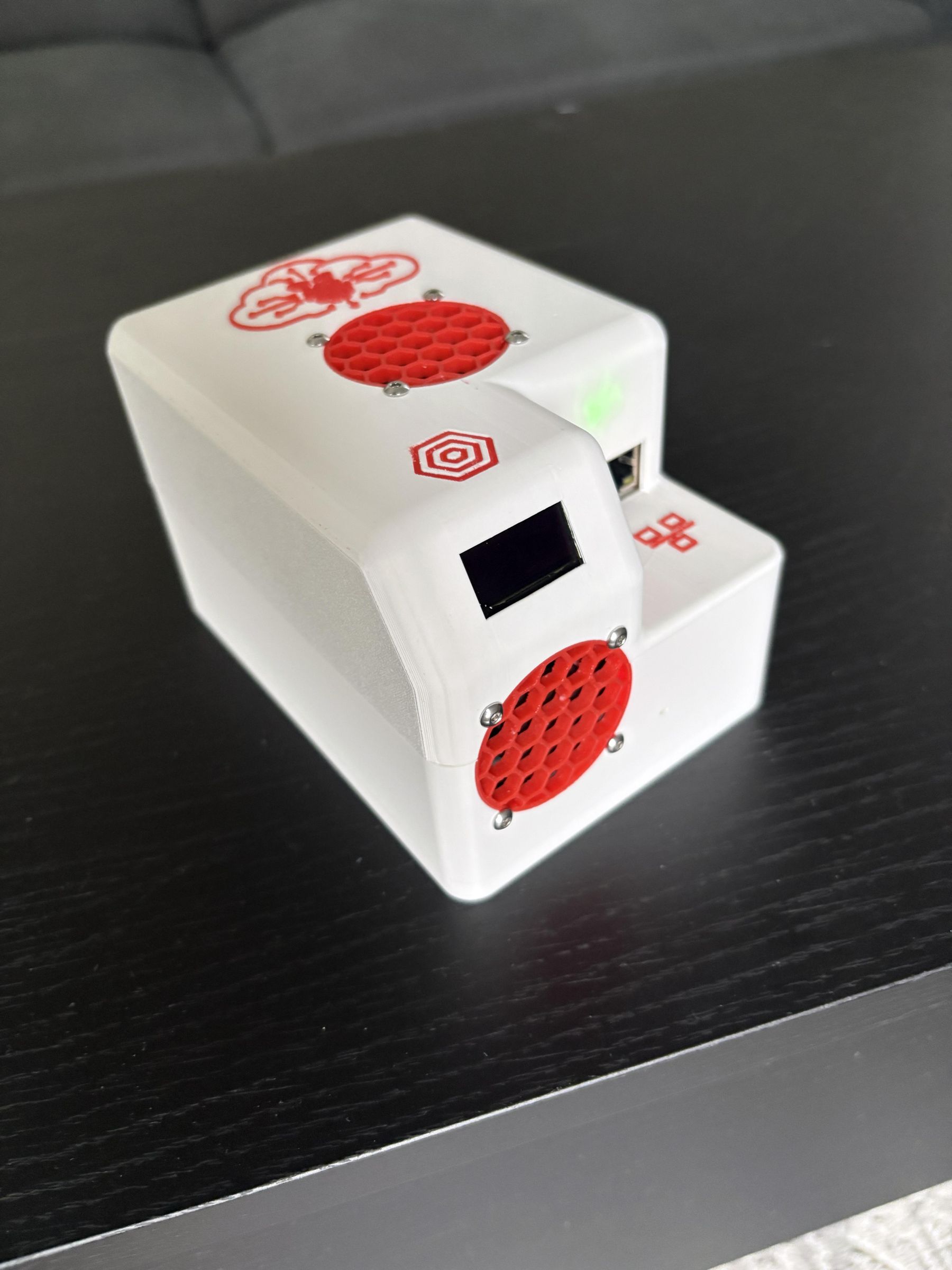
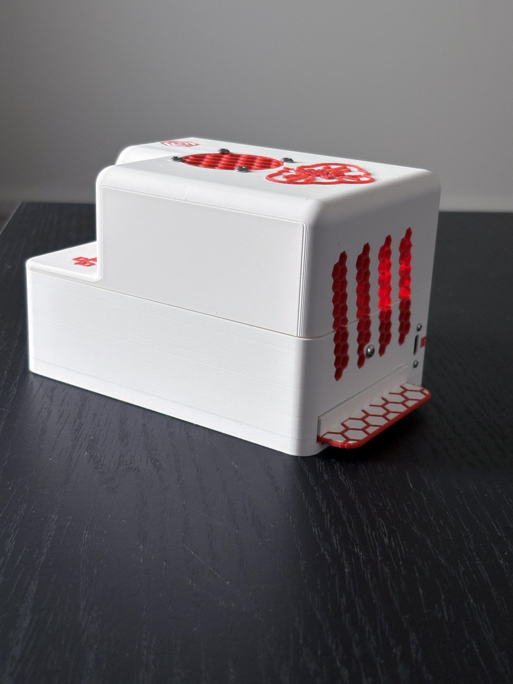
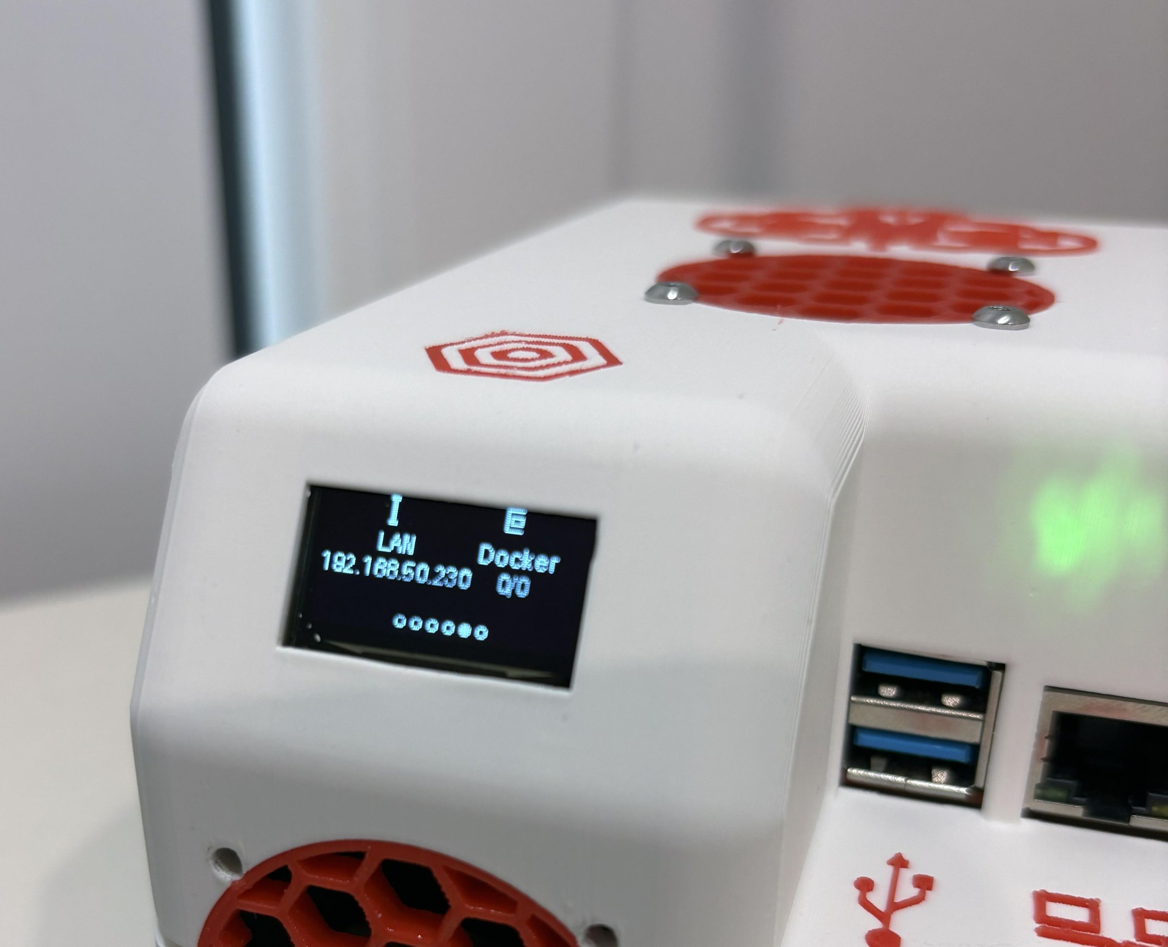
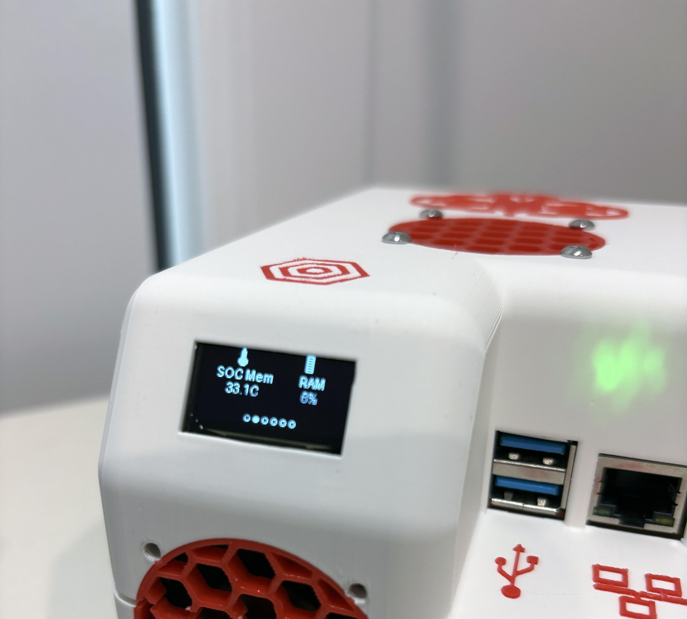
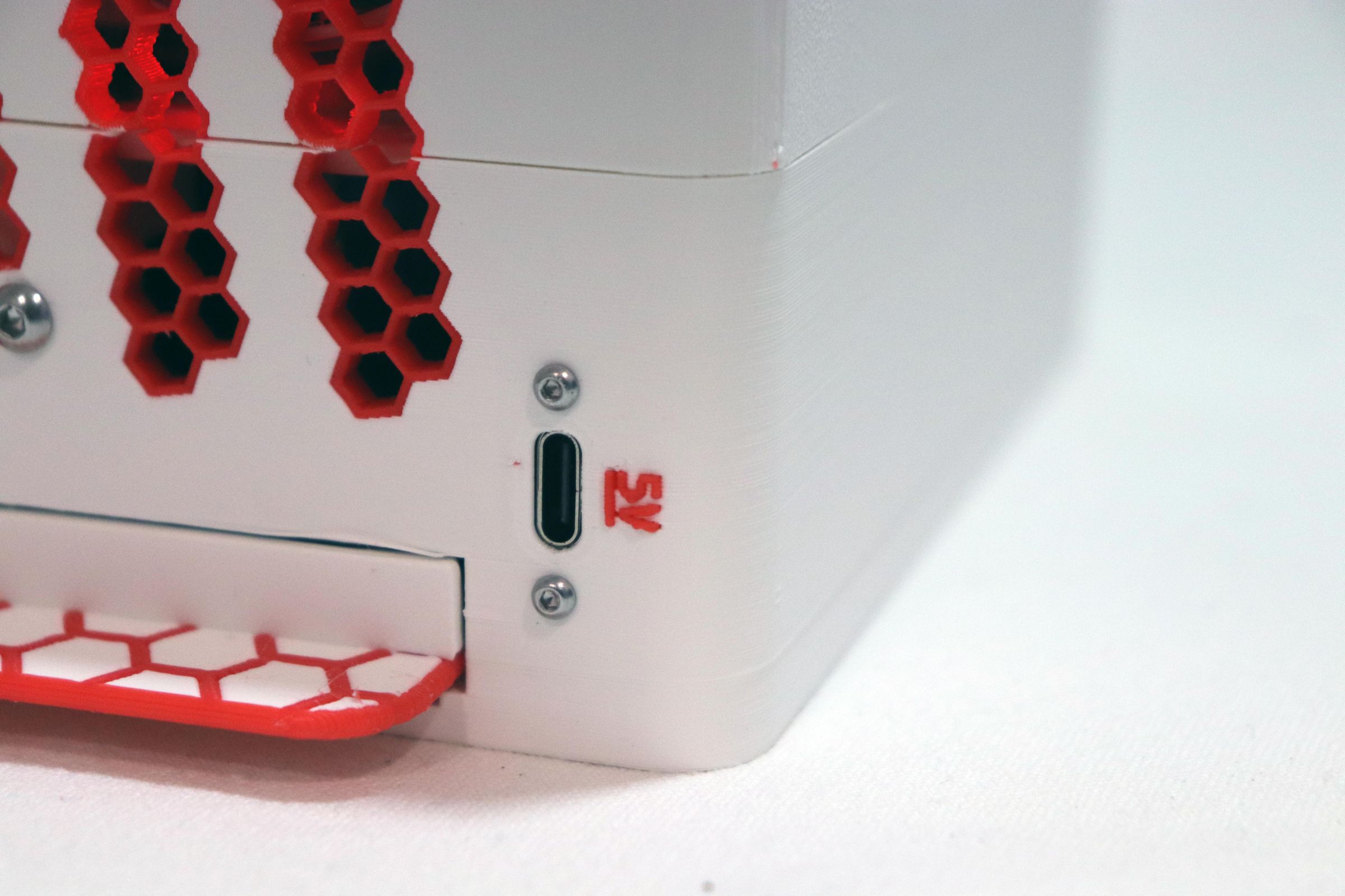
Have you ever had your home server, NAS, or Home Assistant box go down mid-task because of a brownout, tripped breaker or outage? This project fixes that permanently by building a UPS (a battery backup) into your server itself!
This is a fully 3D-printed, self-contained Raspberry Pi server Lifepod with:
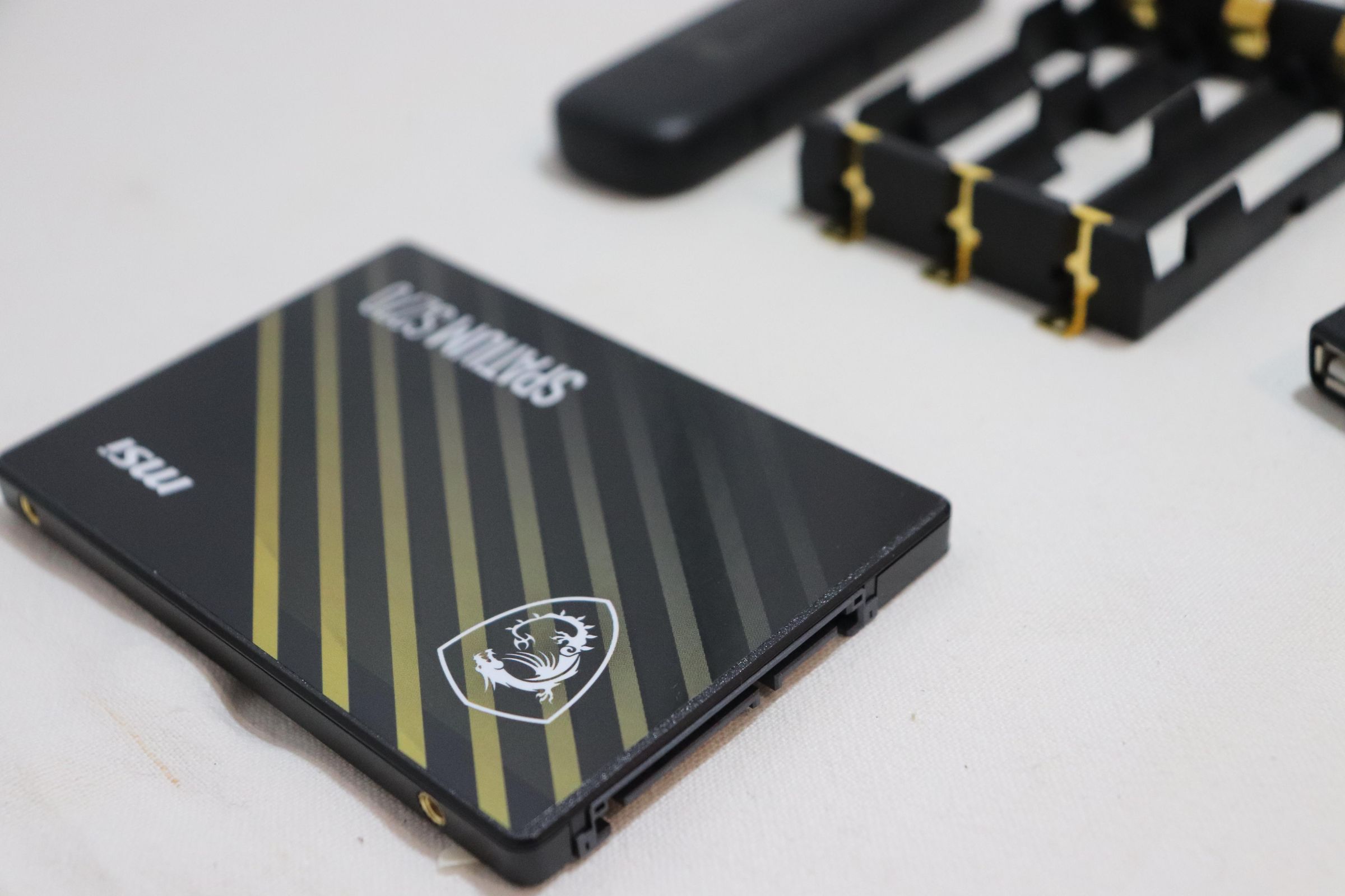
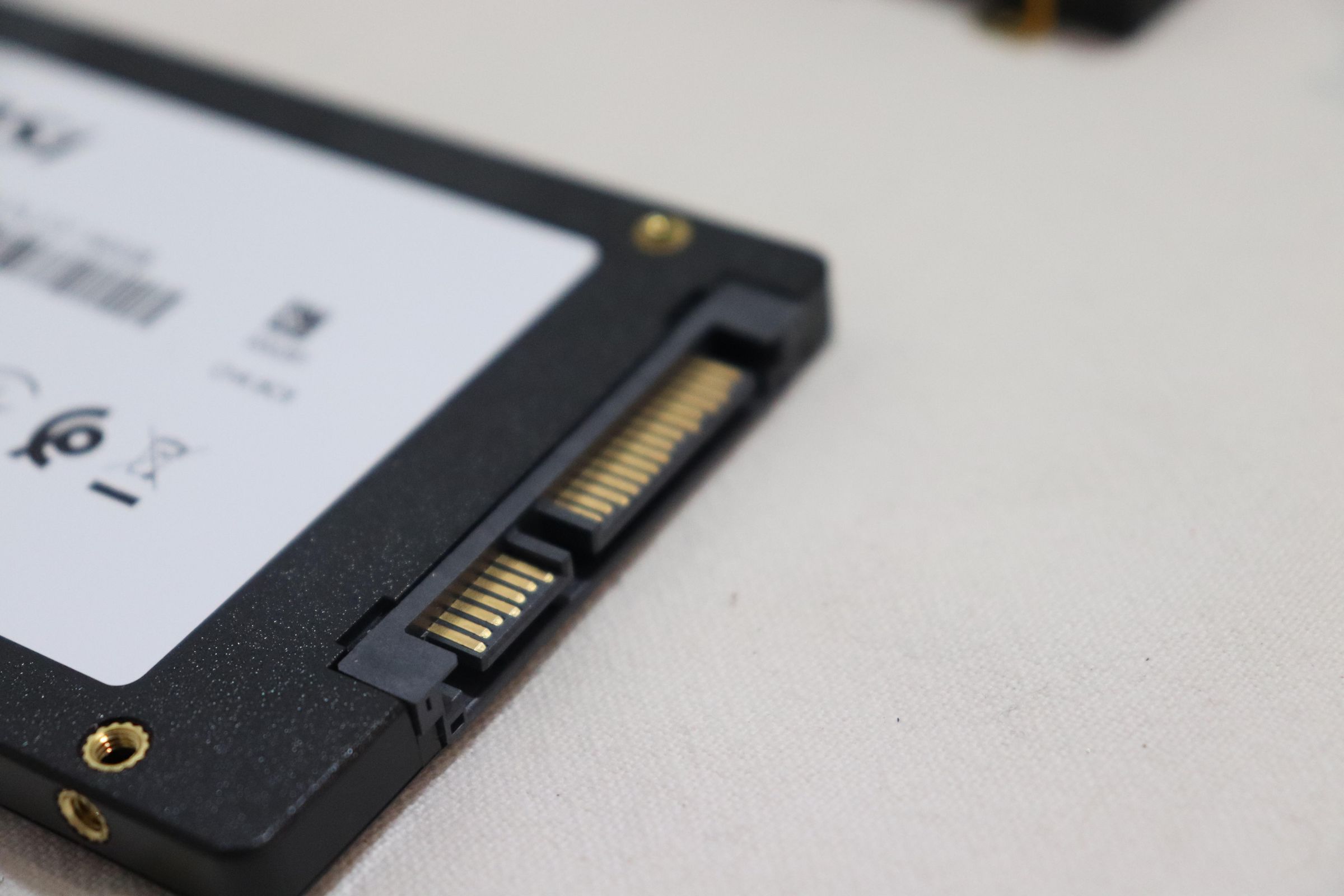
- A hot-swappable SATA 2.5" Drive (via USB) for real NAS-like storage
- 18650 lithium cells built-in, for up to ~6 hours of use!
- Active cooling (two dual 40mm fans)
- A 0.96" OLED status display
- A capacitive touch sensor + physical button for control
- A cellular (LTE) USB dongle with emergency hotspot fallback
The whole thing is designed so that the battery pack is built into the device and not an aftermarket attachment. It's different from most "UPS HAT" modules and projects online, which treat the battery as a glorified capacitor. They attach a small cell battery that can provide a few minutes of runtime, but, in a blackout, you'll want your personal data and other programs accessible for much longer than that.
This project has a proper multi-cell holder, and a scalable battery system (from 1-3) without needing to redesign anything! More on the battery system in Step 10 below.
What can this server do?
Once assembled, the Raspberry Pi can host a multitude of software:
- Nextcloud – personal cloud storage (which I'll be doing)
- Home Assistant – smart home hub, still running through short power blips (which I've done!)
- RaspiMonitor – a custom monitor script that drives the status OLED, and can trigger the LTE dongle's hotspot mode if your home internet drops!
Because the battery bank sits between the wall power and the Pi at all times, a power cut is invisible to the Pi and causes no reboot, no corrupted SD card and no dropped connections!
Supplies
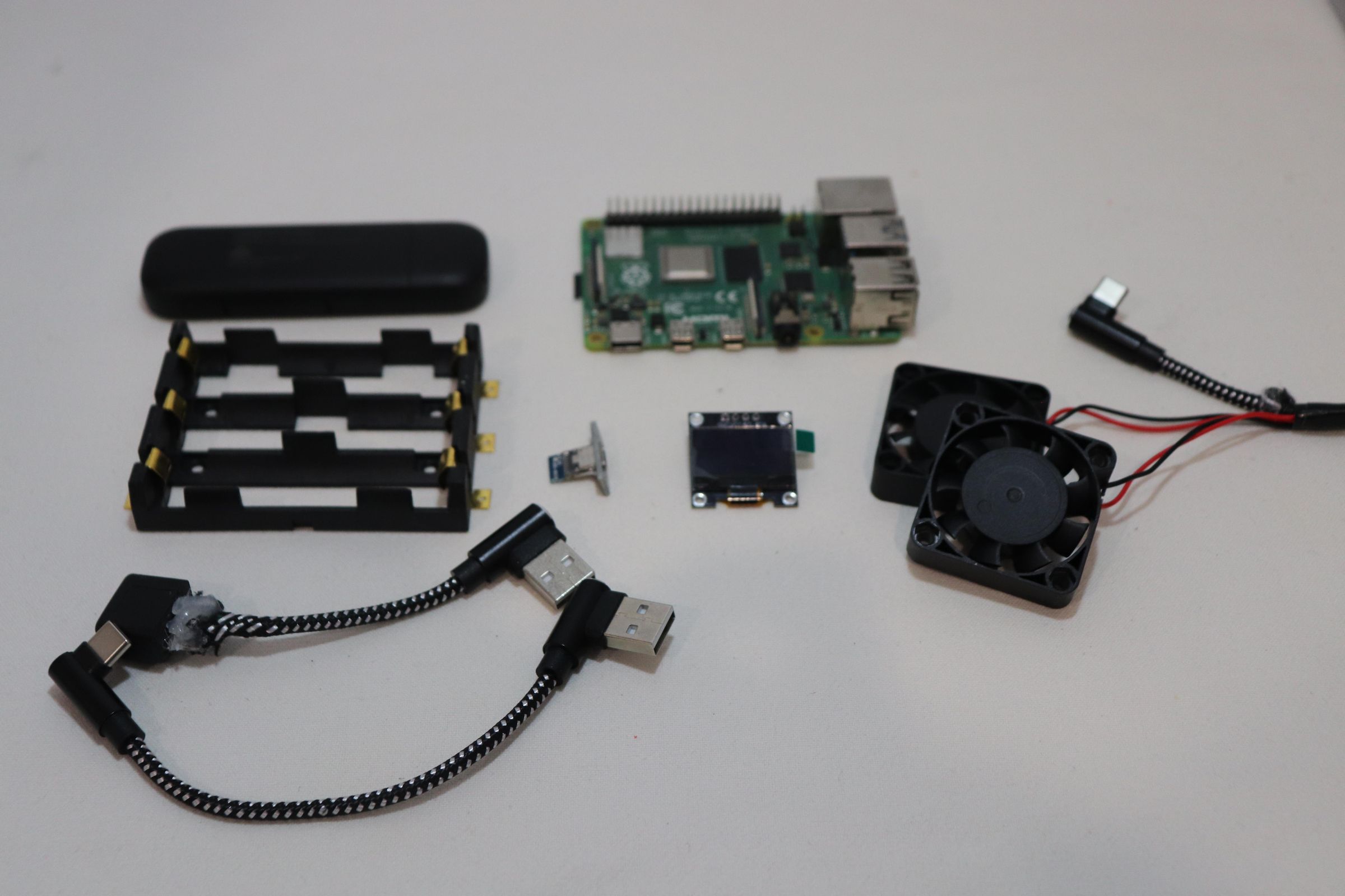

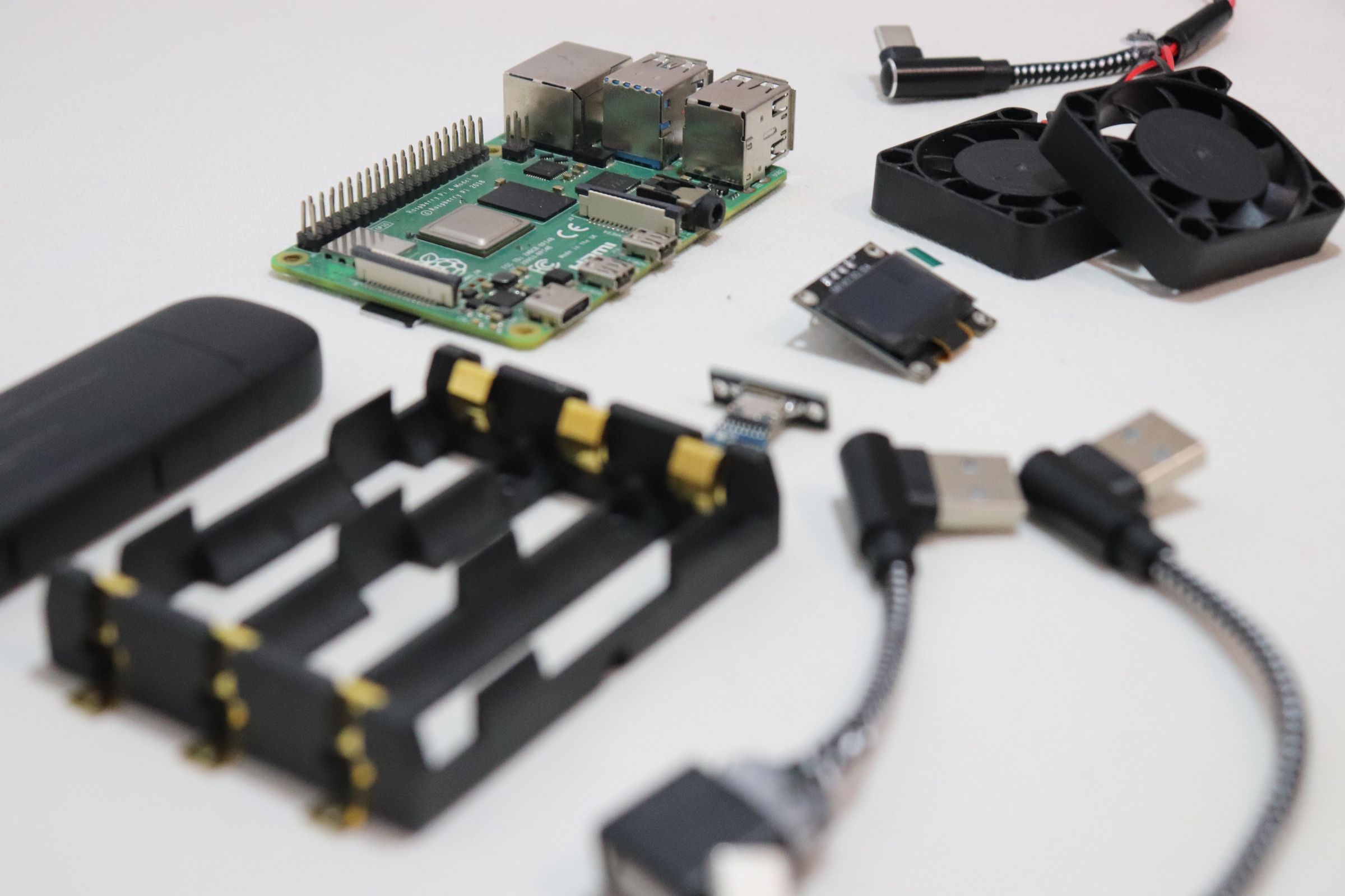
Electronics
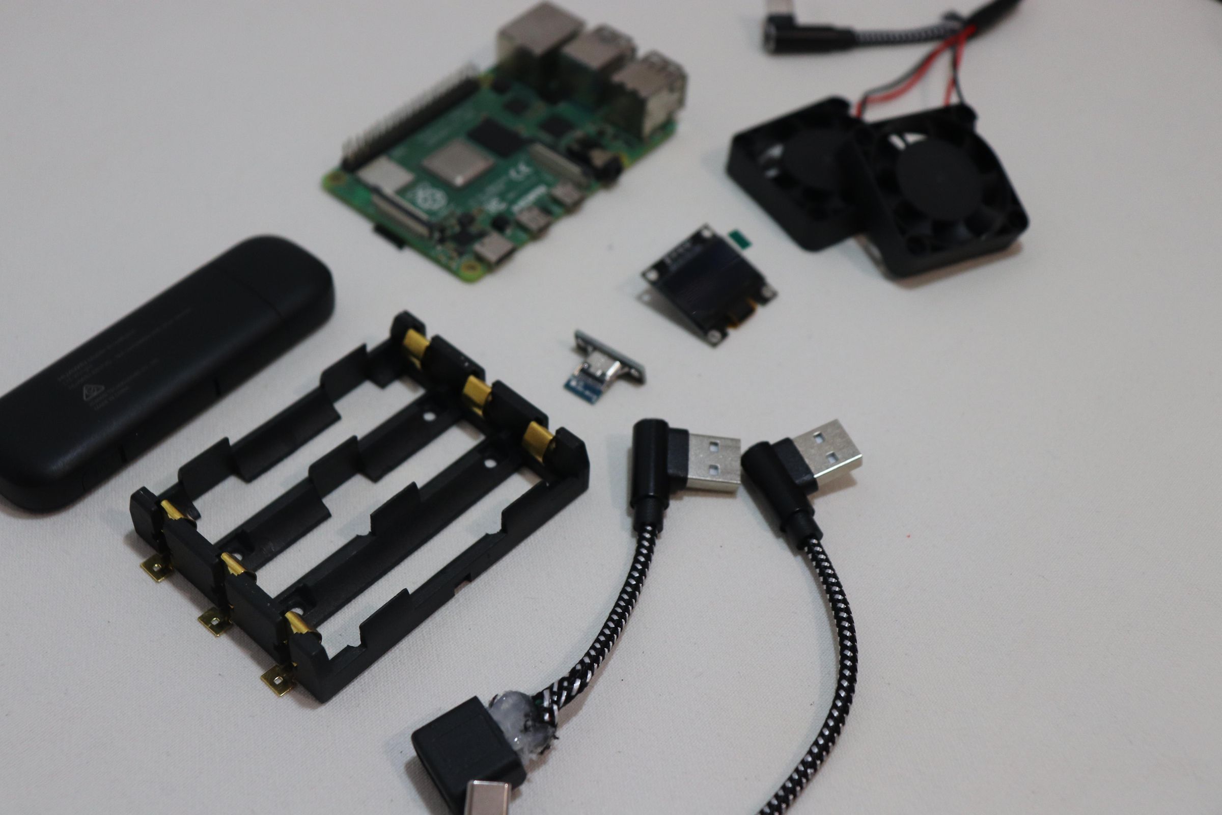
- Raspberry Pi 3/4/5
- 2x 4010 5V DC Fan
- 5V UPS module (MHCD42) - Important: Get a higher quality module if possible; the MHCD42 is unreliable at times.
- 3x 18650 3.7V Li-ion cells - I ran 2 to start, upgradable easily to 3
- 3x 18650 battery holder (ensure this is wired in parallel)
- SATA-to-USB adapter
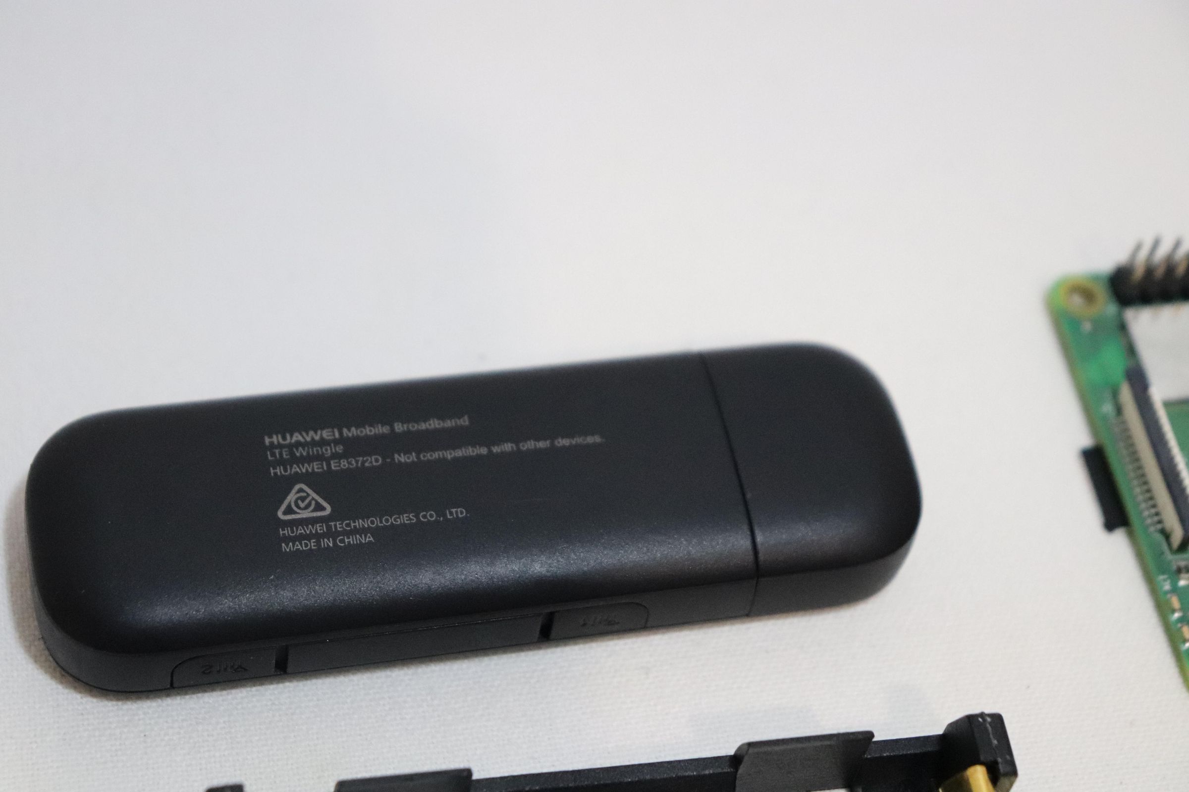
- SIM-to-USB (LTE) dongle - I used a Huawei USB LTE dongle, although any should work.
- 0.96" I2C OLED display (SSD1306)
- TTP223 capacitive touch sensor module
- USB-C power input breakout/module
- Right-angle USB-C cable (super short)
- Right-angle USB-A/USB extension cable (super short or DIY)
Hardware
- 8xM2x12 screws + nuts (USB-C power module mount)
- 2xM3x8 screws + nuts (L-joint bracket)
- 4xM3x16 screws + nuts (fans + mounting plates, x2 sets)
- 4xM5x12 screws (case closure)
- 2xSmall SSD-drive screws (for the drive handle)
- Hot glue gun + glue sticks
- Soldering iron (also doubles as a plastic-welding tool in this build)
Printed Parts
- Bottom case
- Top case
- Battery platform
- Raspberry Pi mounting platform
- Fan mounting bracket
- L-joint bracket
- Drive handle
3D Print the Case and Parts
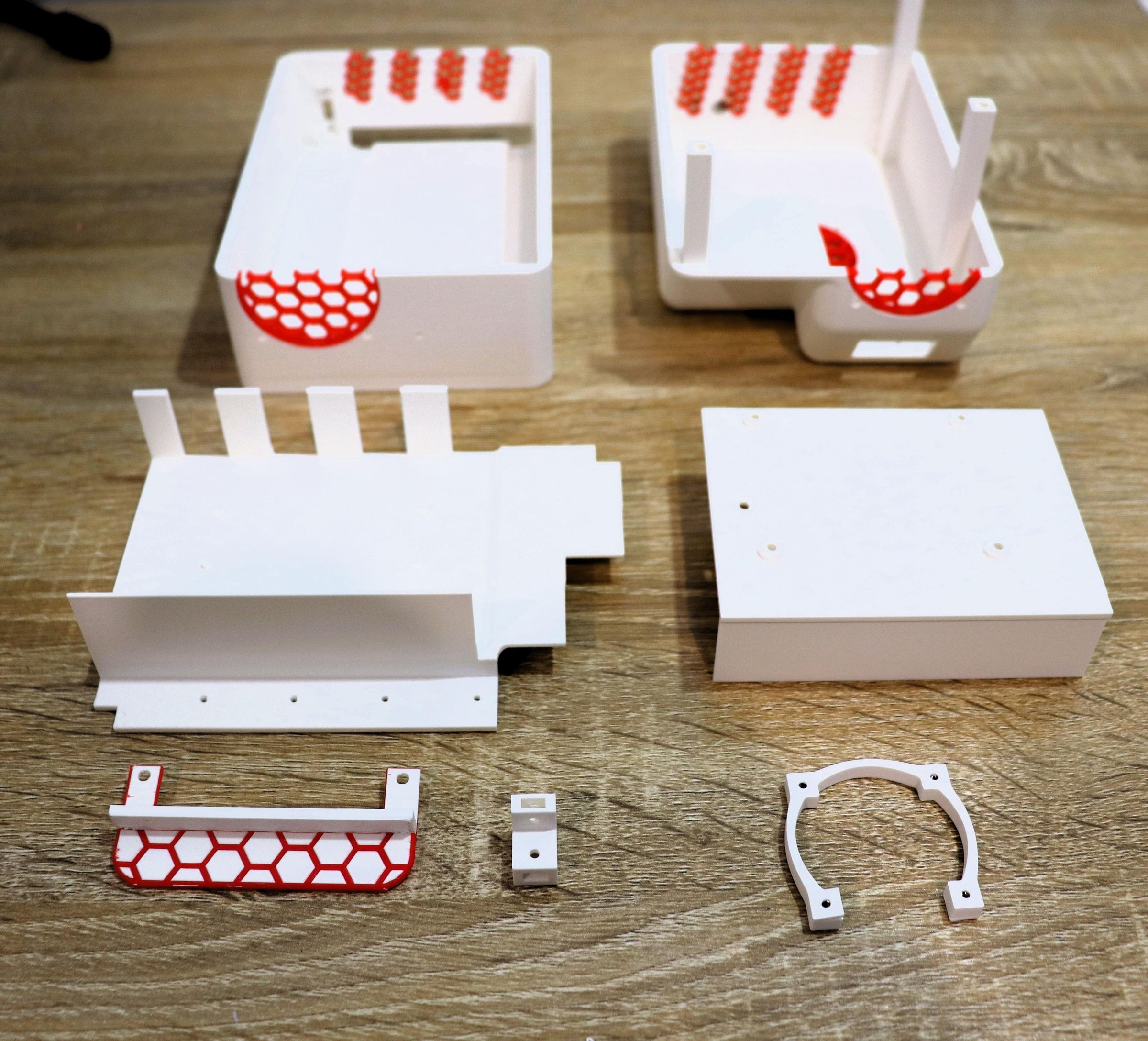
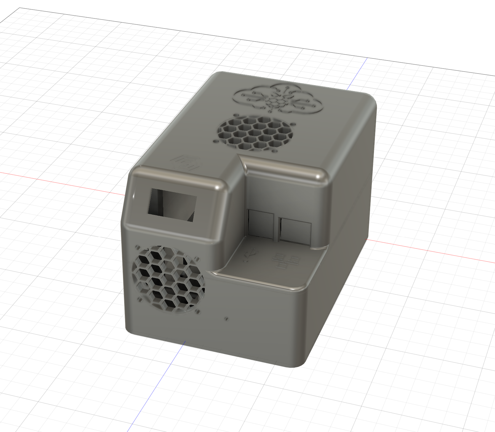
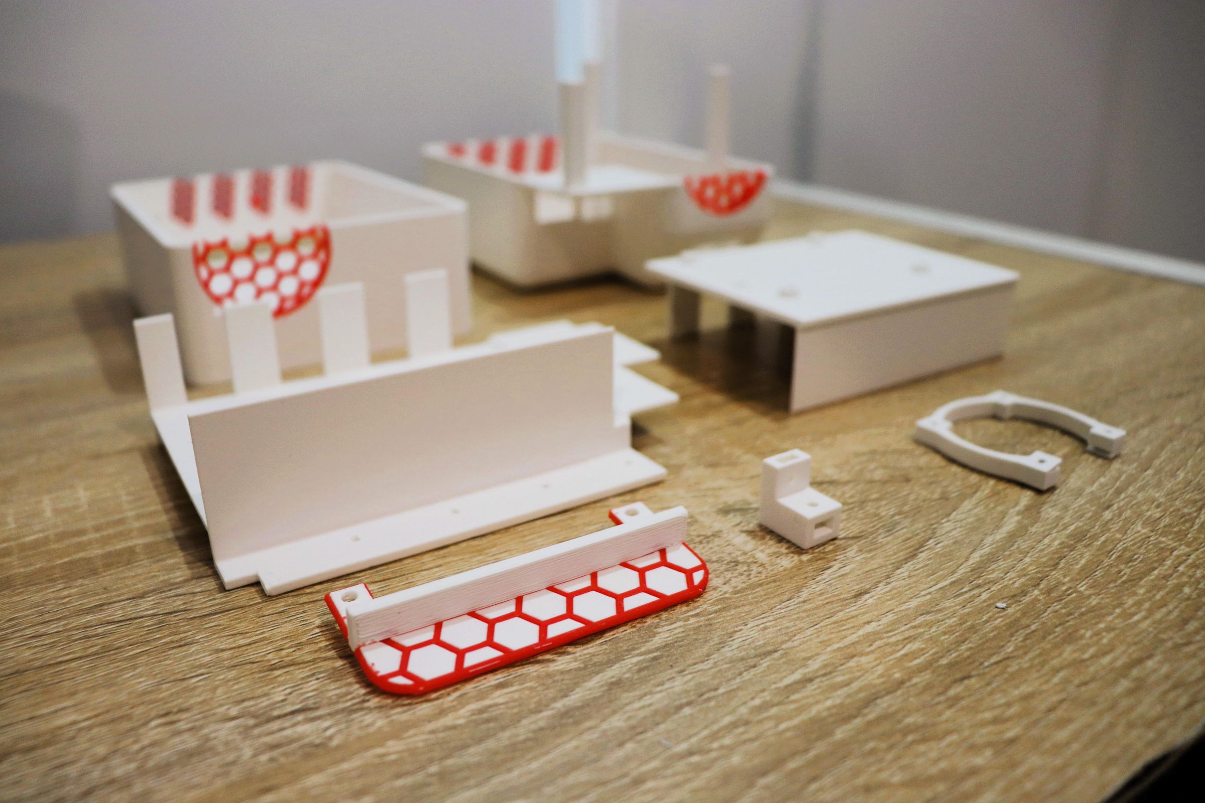
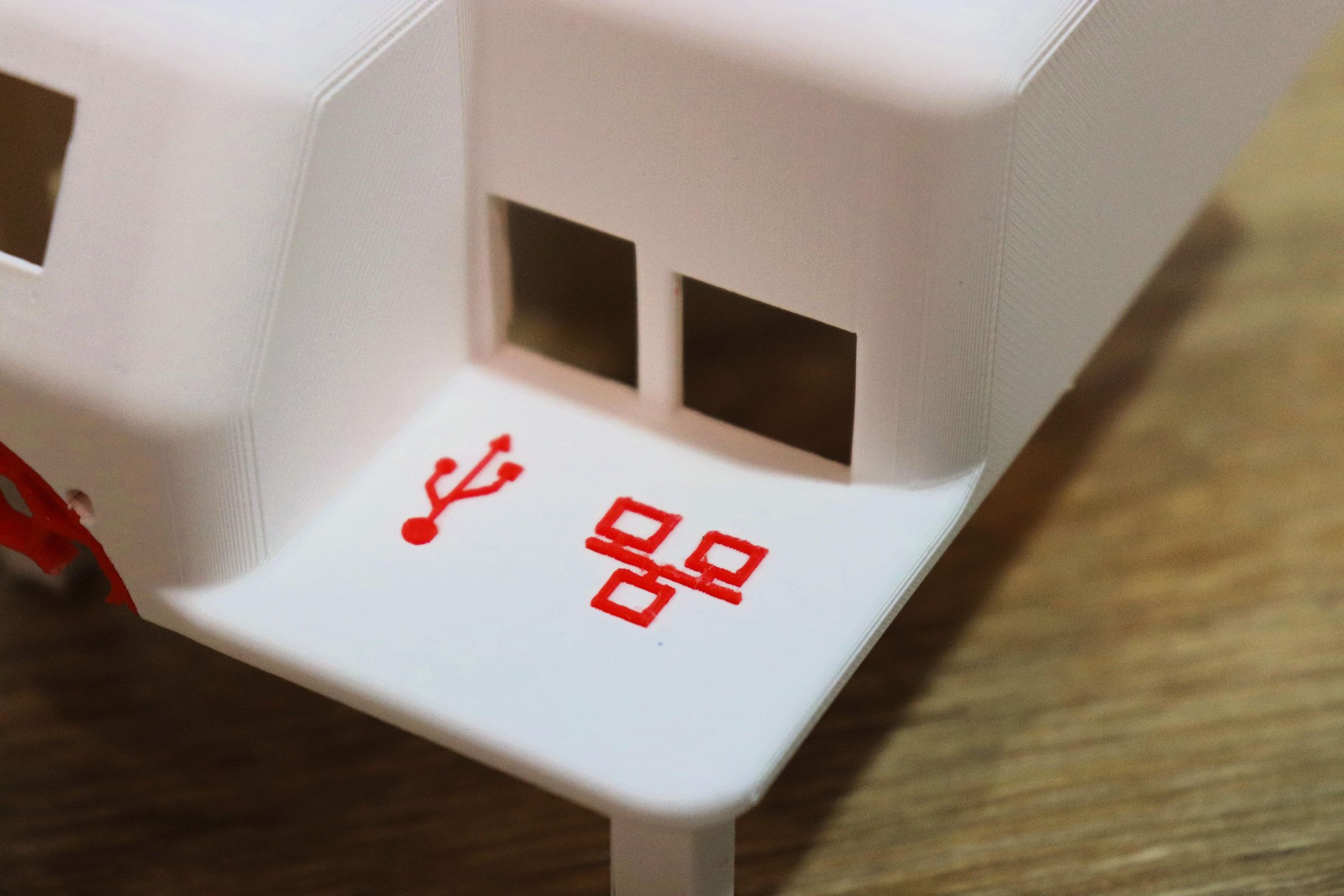
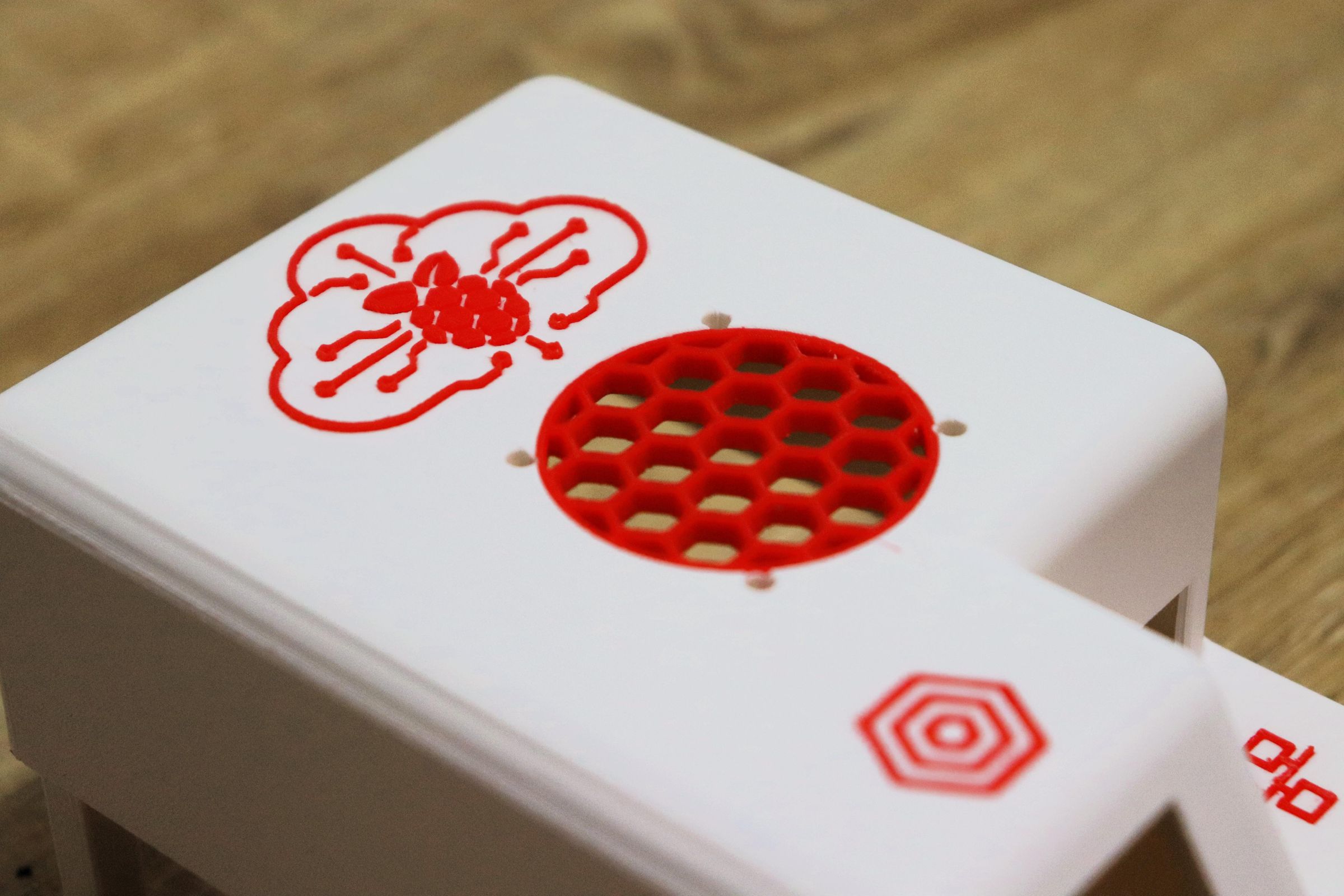
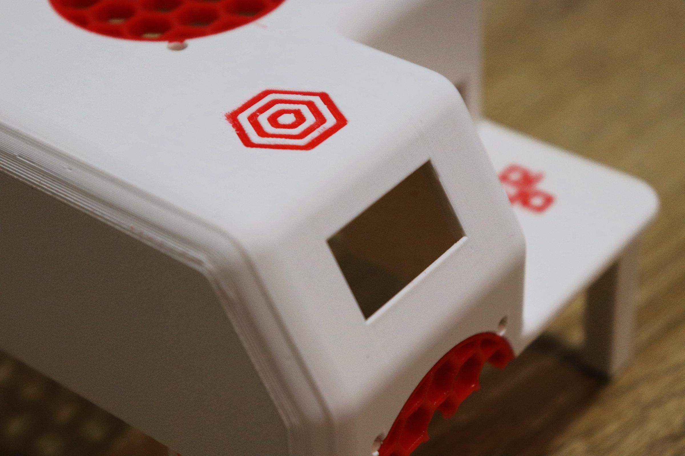
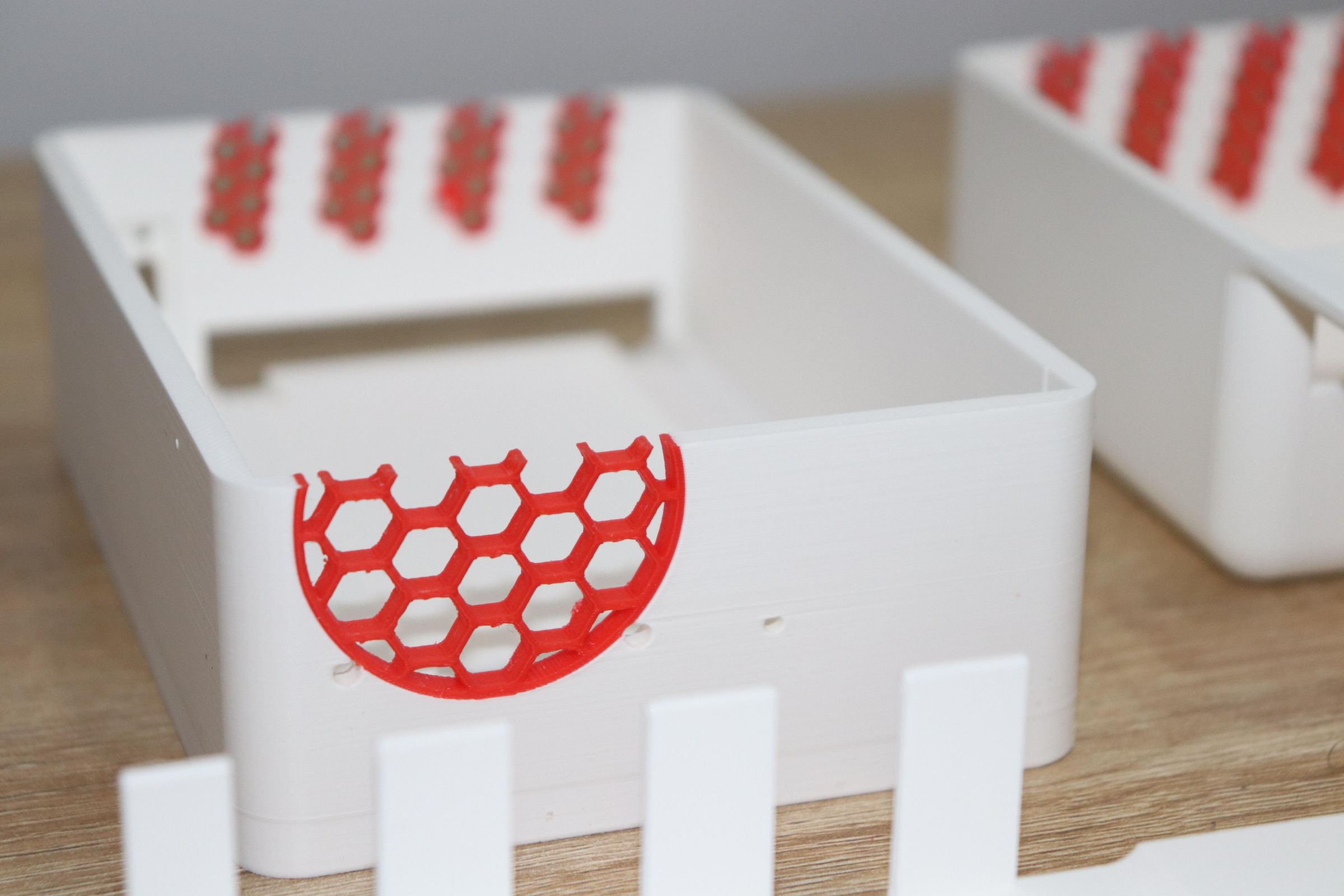
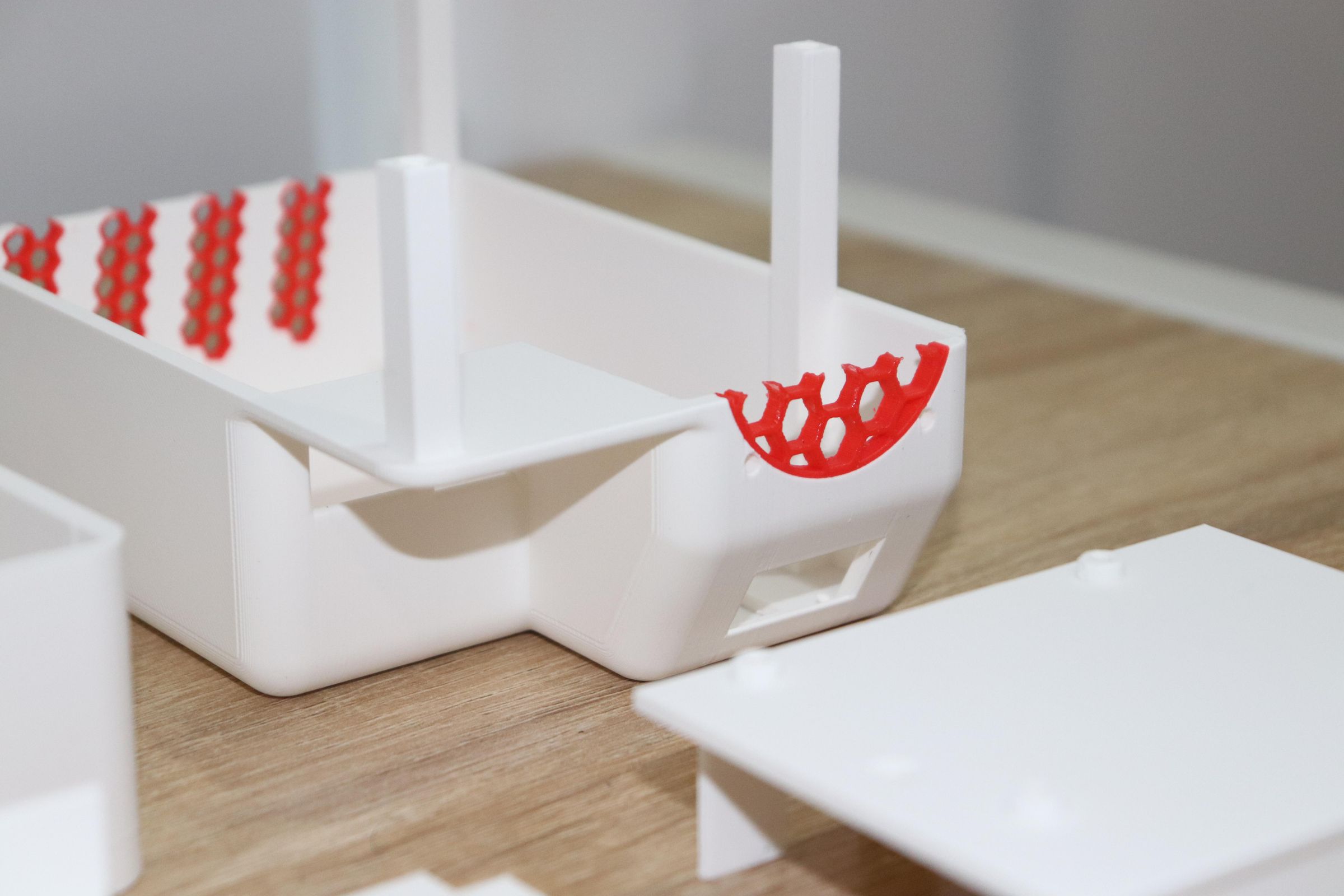
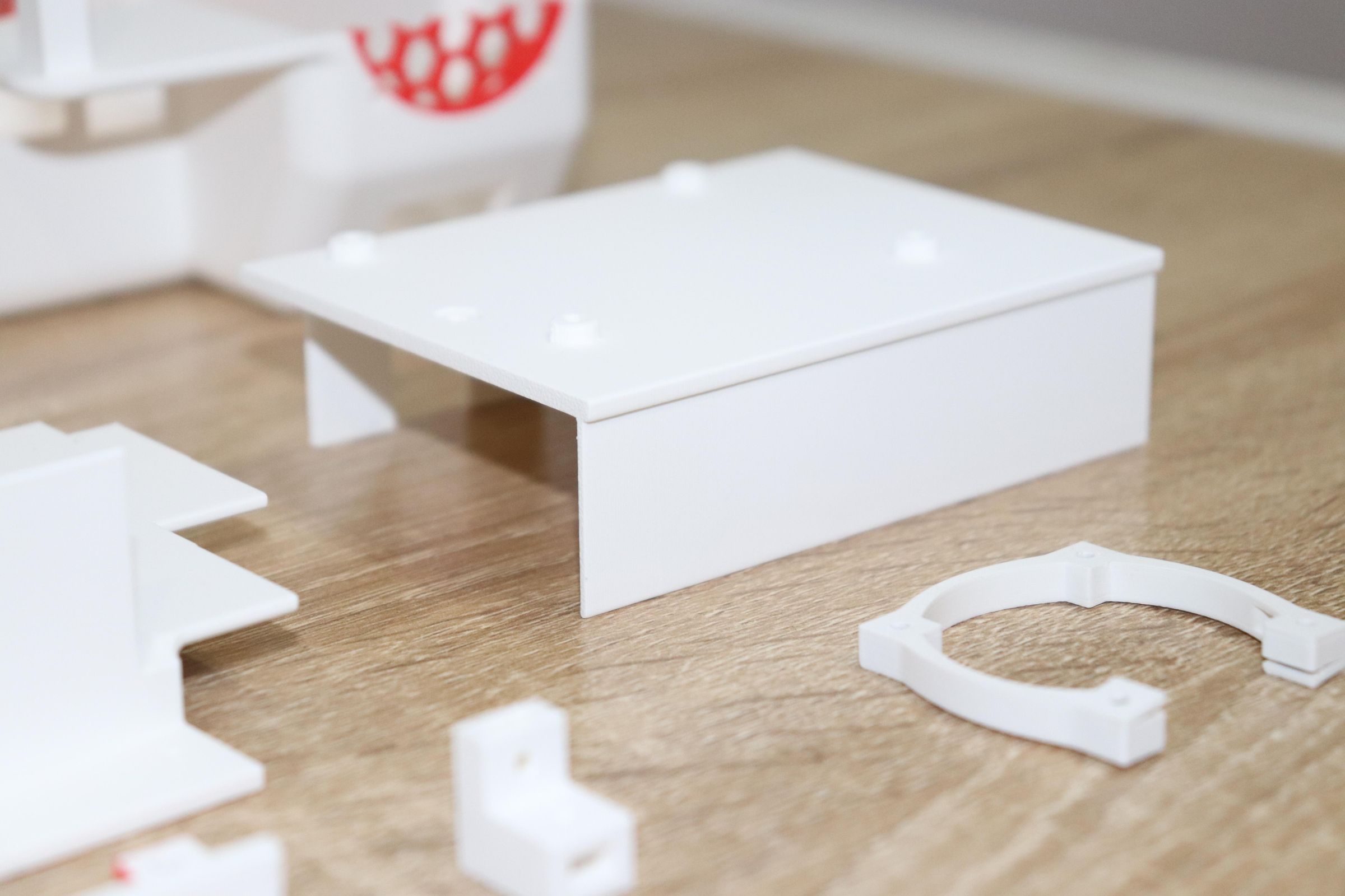
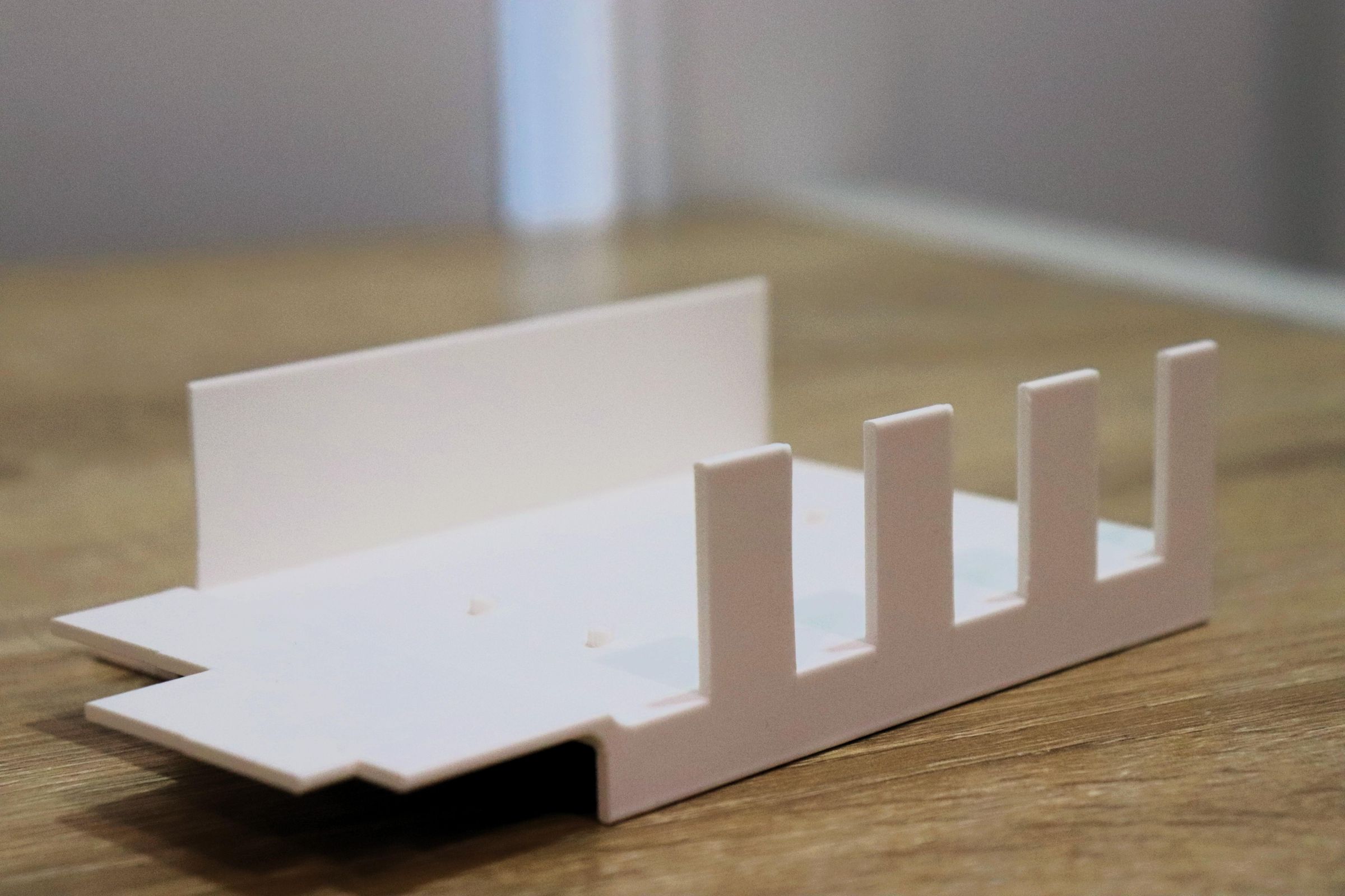
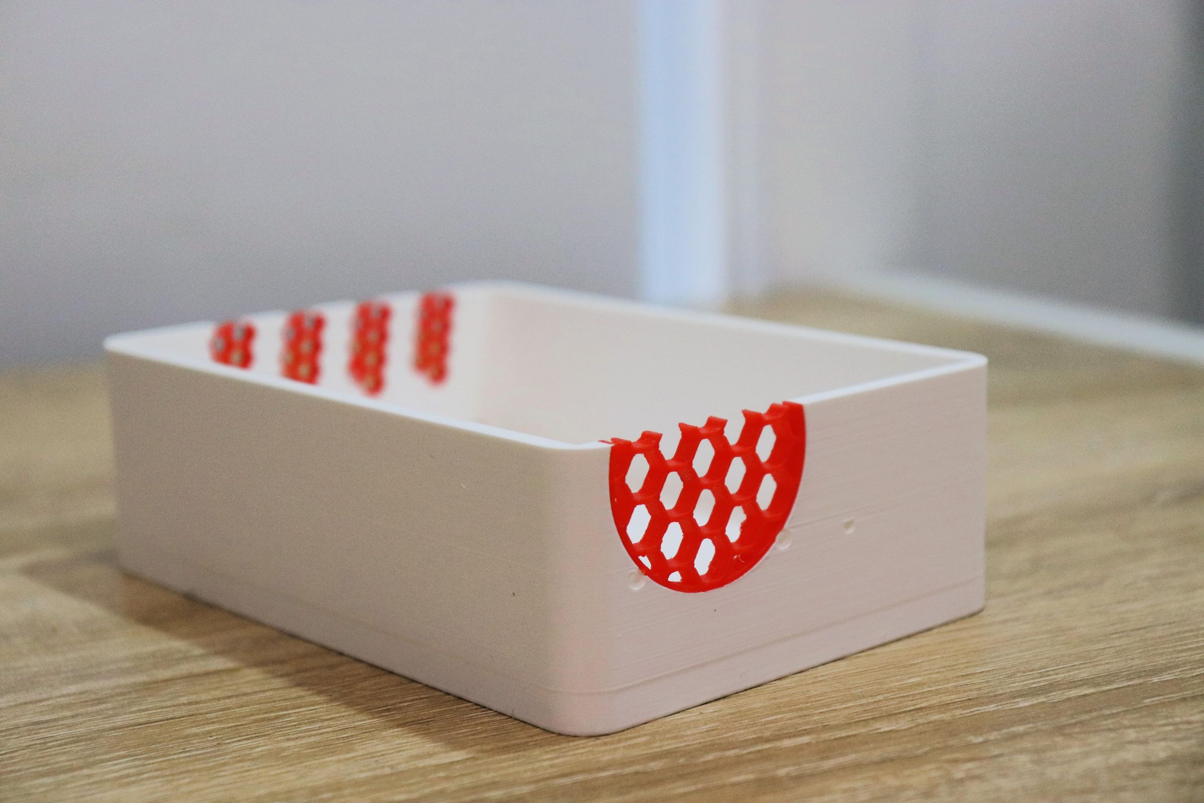
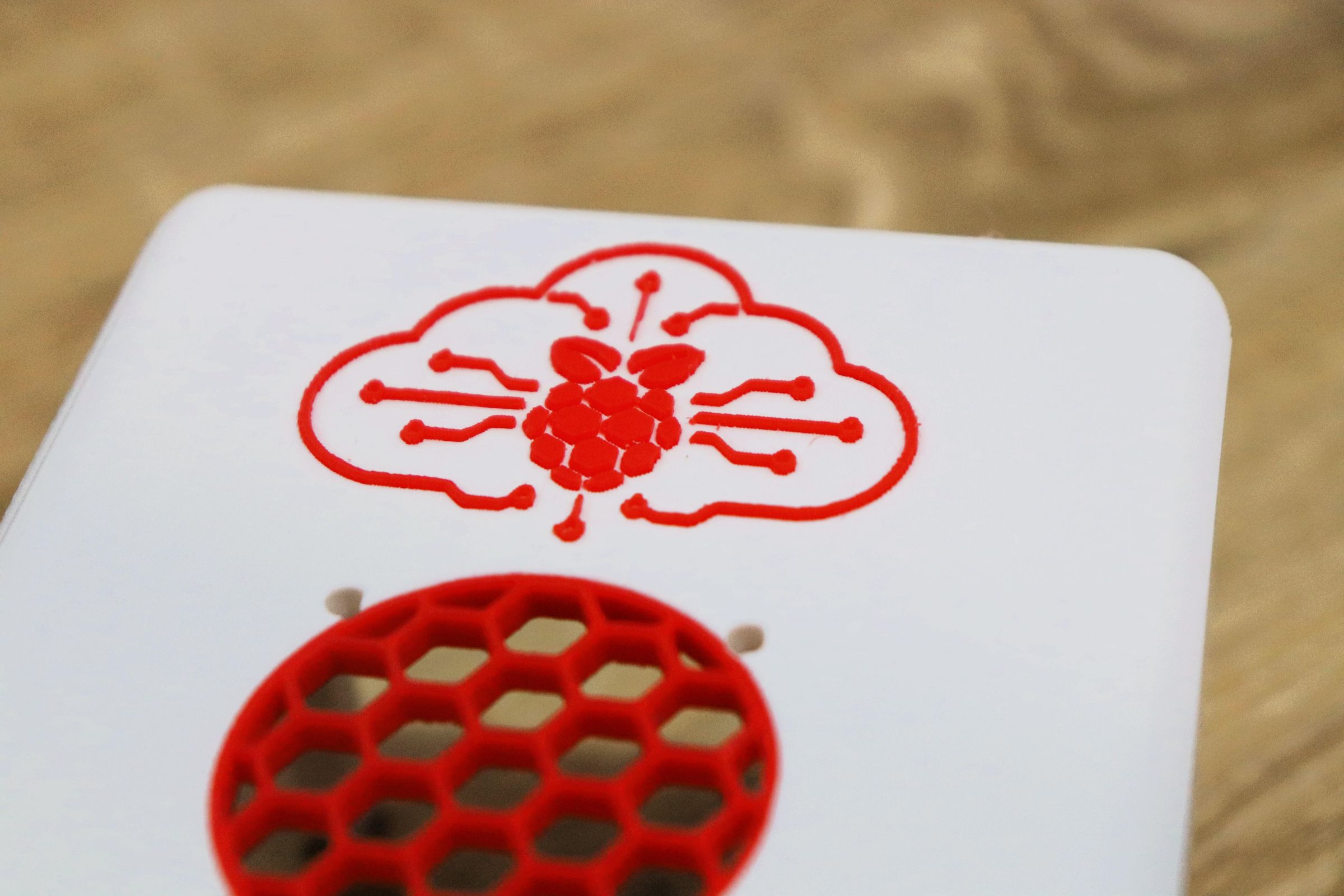
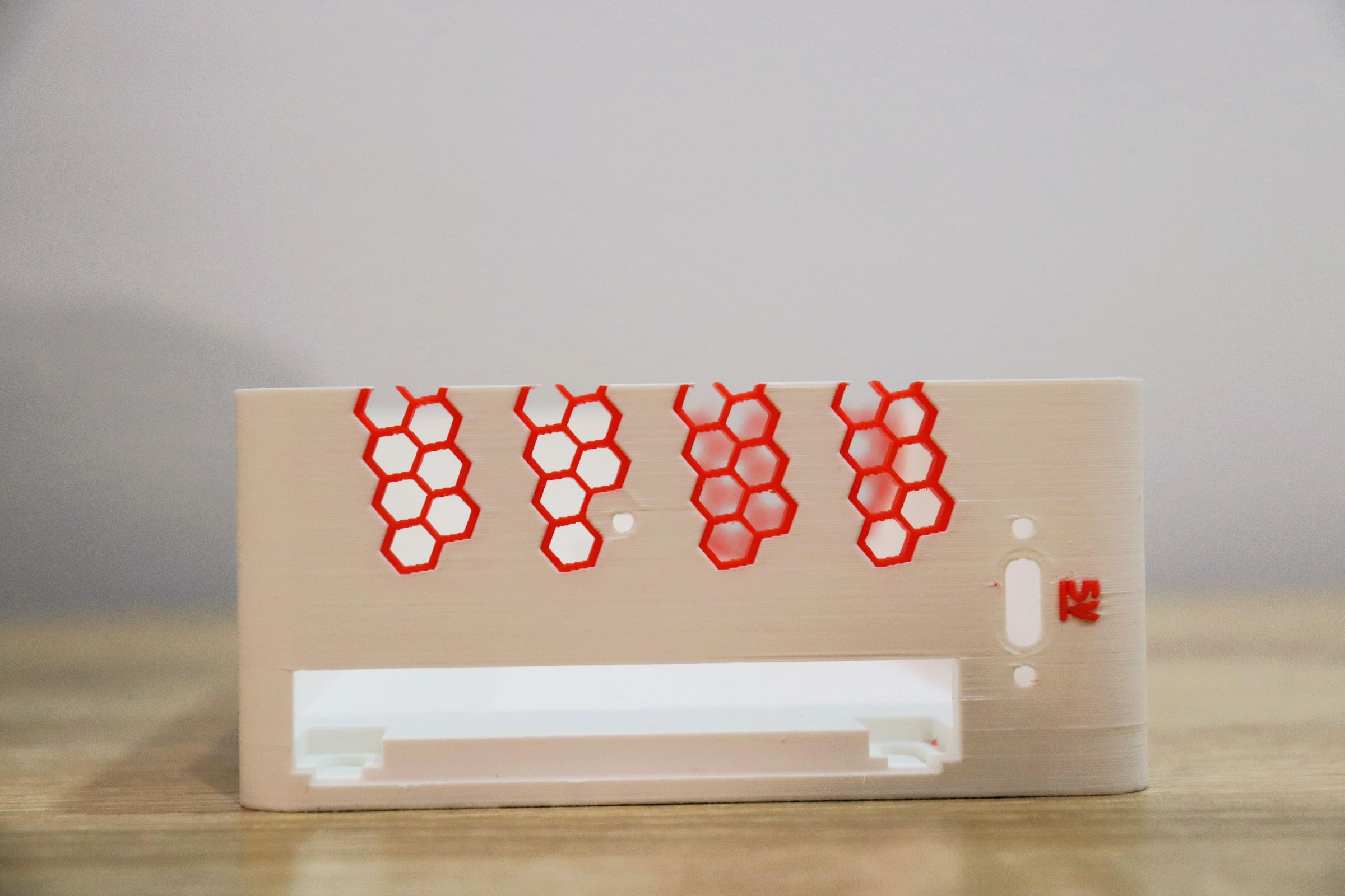
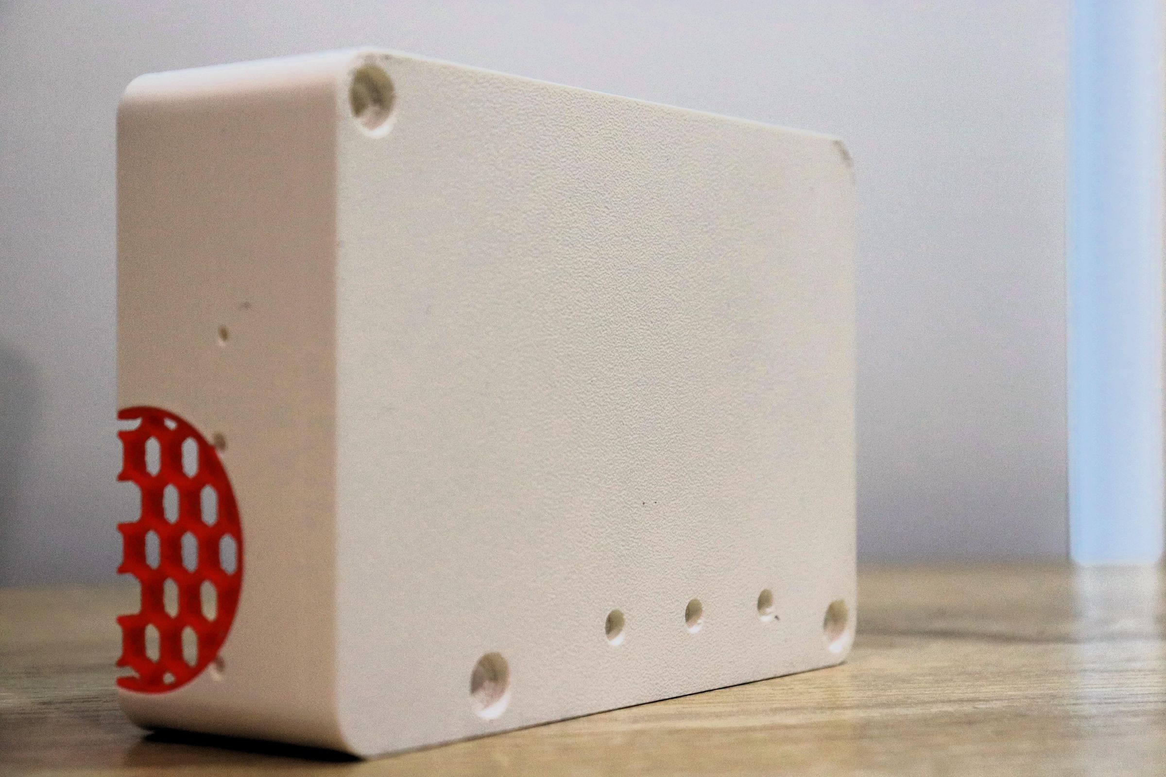
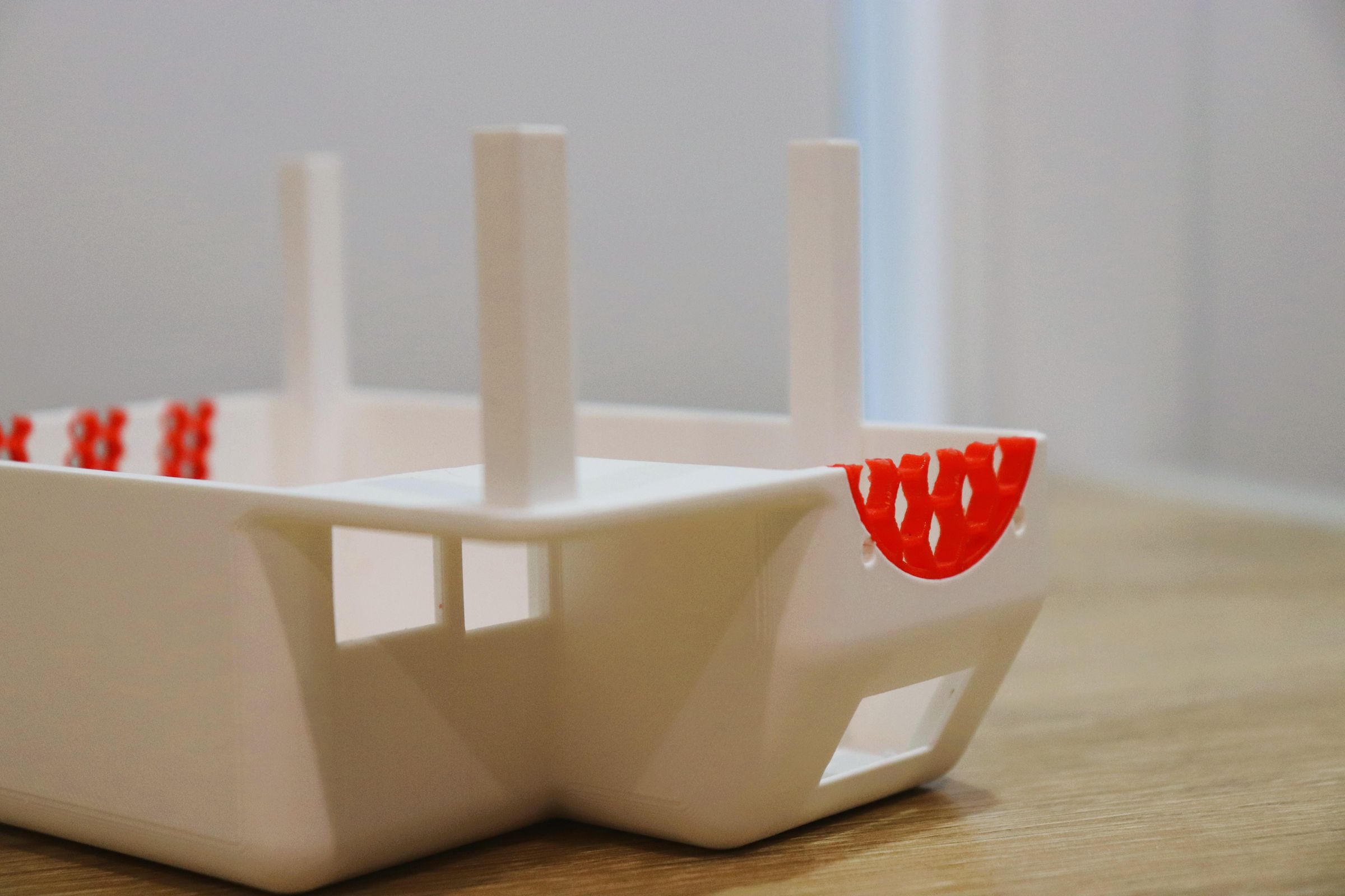
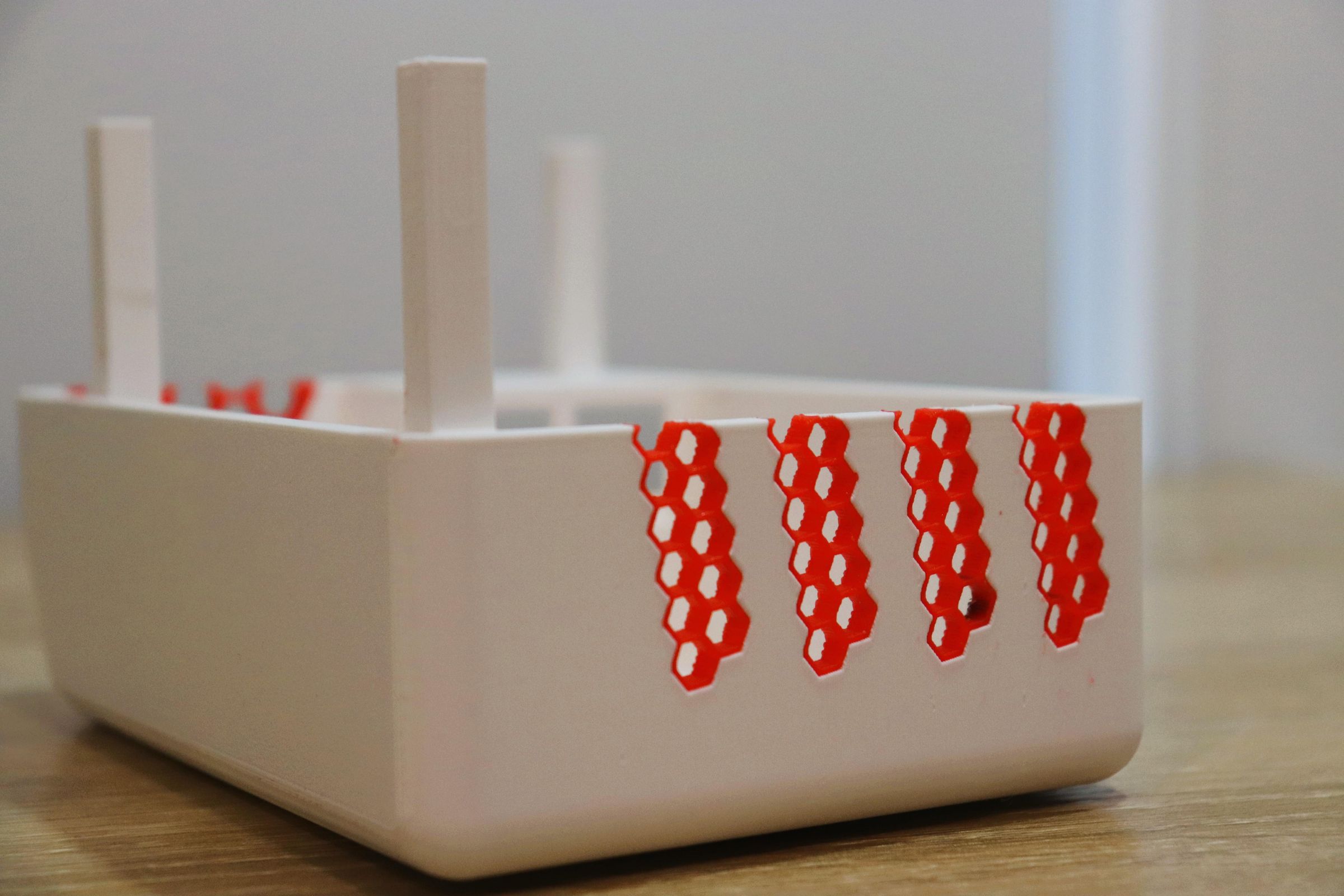
Grab the model files from Makerworld and print all of the parts listed above.
Suggested print settings:
- Material: PETG recommended for the case (better heat tolerance near the UPS/fans than PLA); PLA is fine if you keep the unit in a cool spot
- Layer height: 0.12–0.2mm, gives a higher quality exterior.
- Infill: 25–35% for the case halves, 10% for the battery platform and Pi mounting platform (these carry little load)
- Supports: Enabled for most parts.
- Walls/perimeters: 3 walls for the case shells, especially around where screws go in
After printing, clean up each part before assembly.
Remove all support material, and use a deburring tool or small knife to clean the model.
You might optionally use a heat gun or source to melt away any stringing on the model (like I did), but be careful not to burn the plastic (like I did)!
Once that's done, do a dry fit of the two case halves and the internal platforms to ensure everything works.
Install the SSD & USB C Board
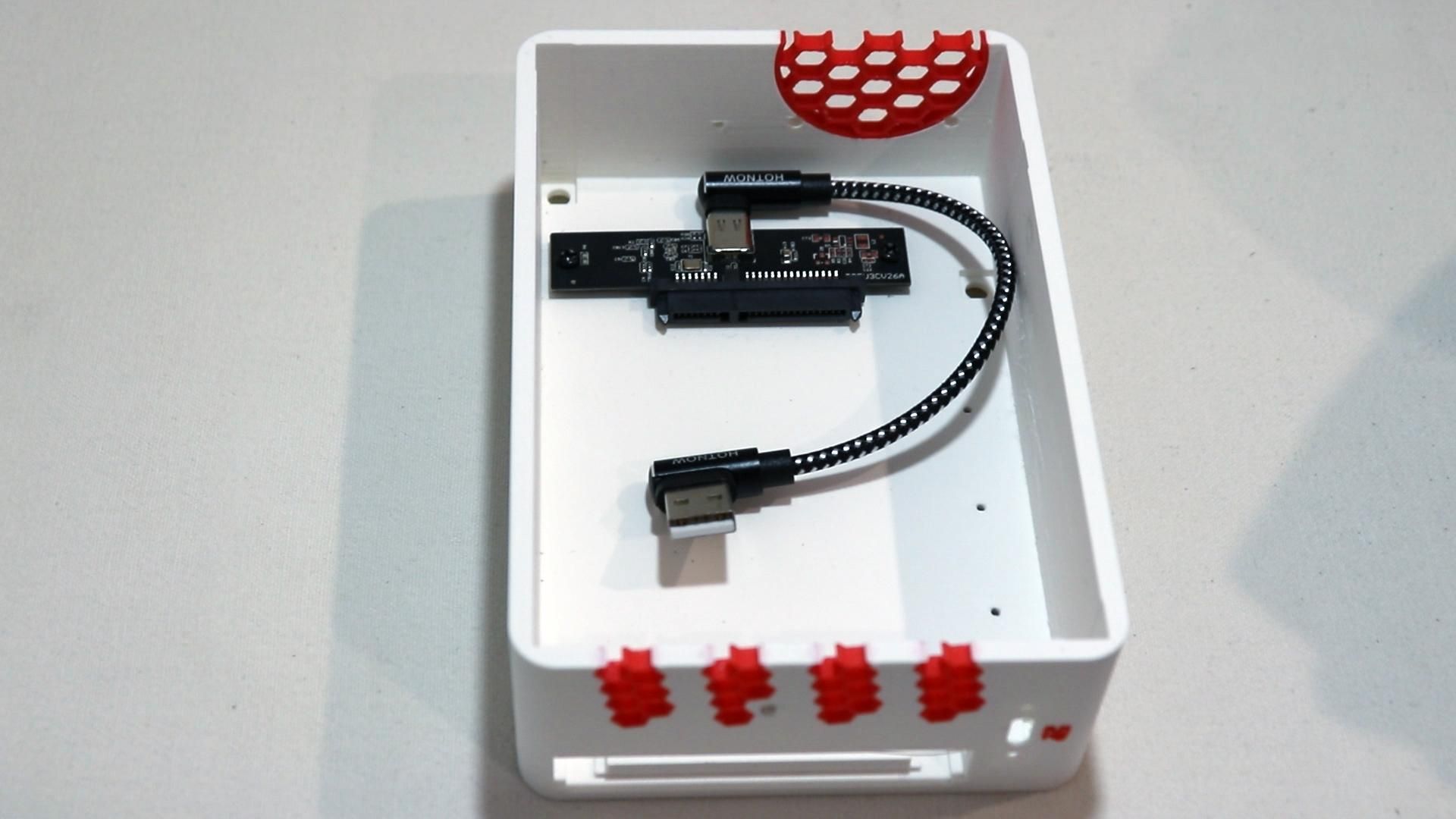
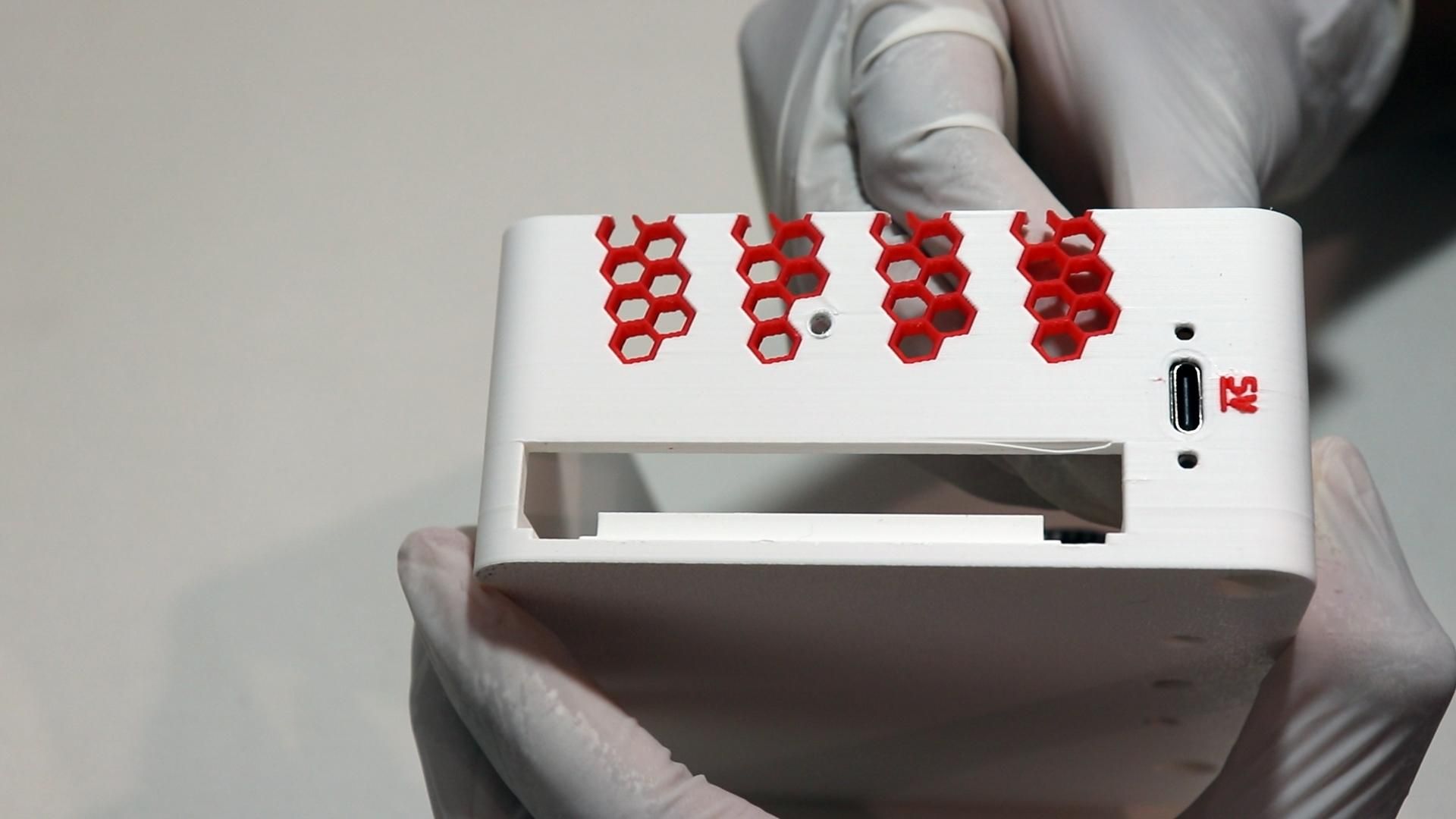
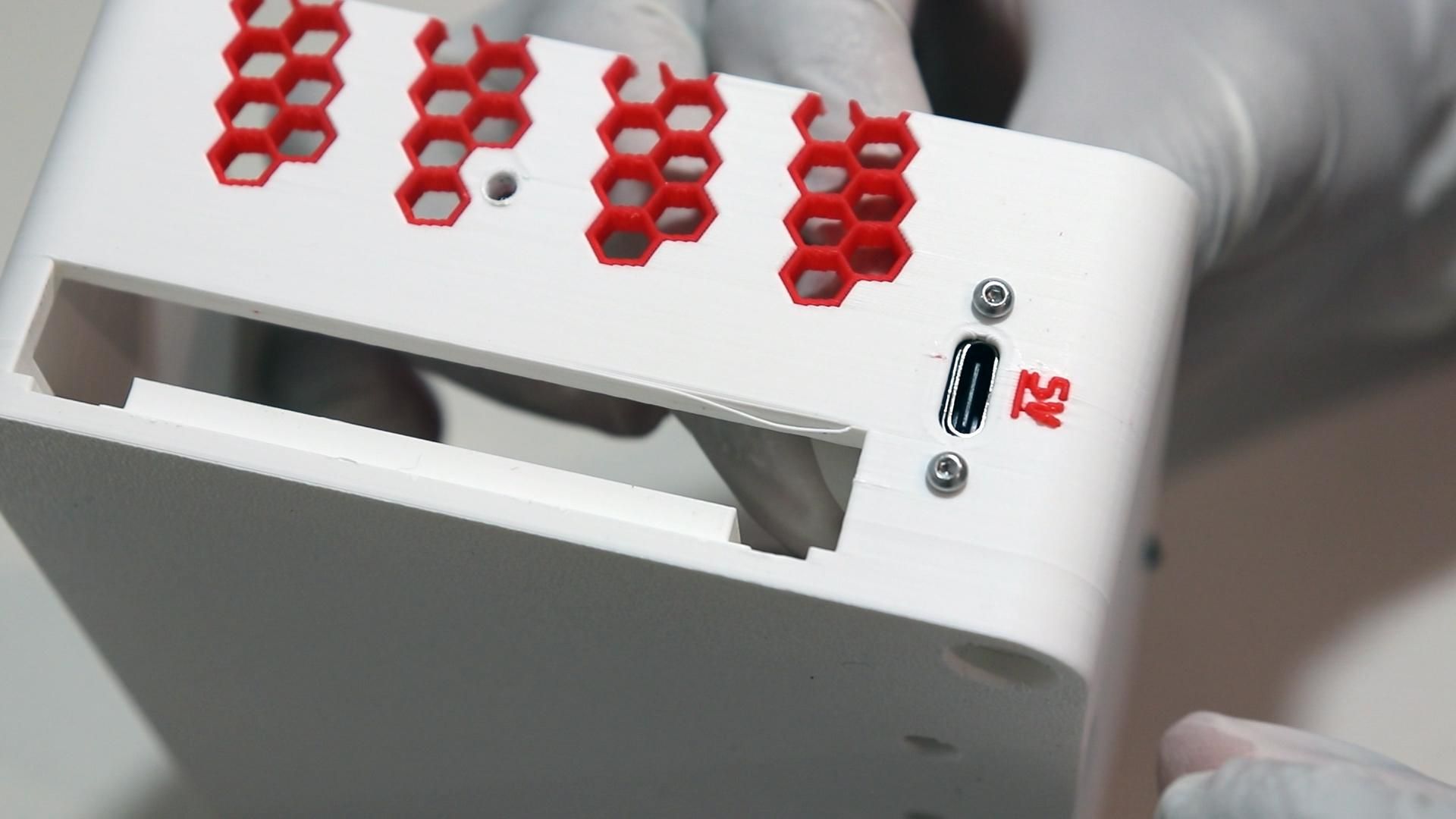
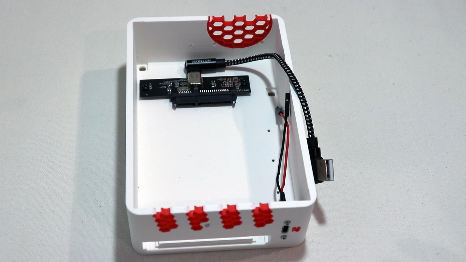
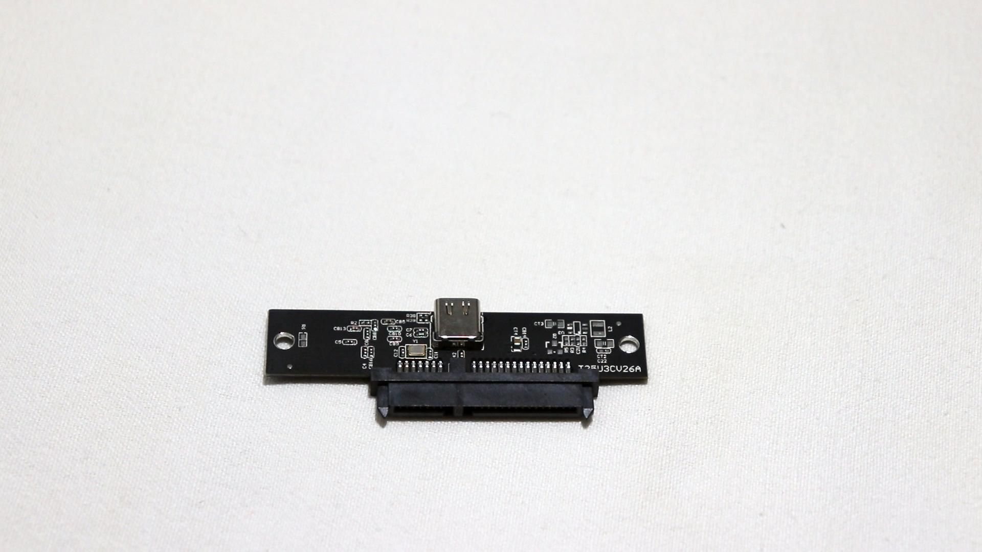
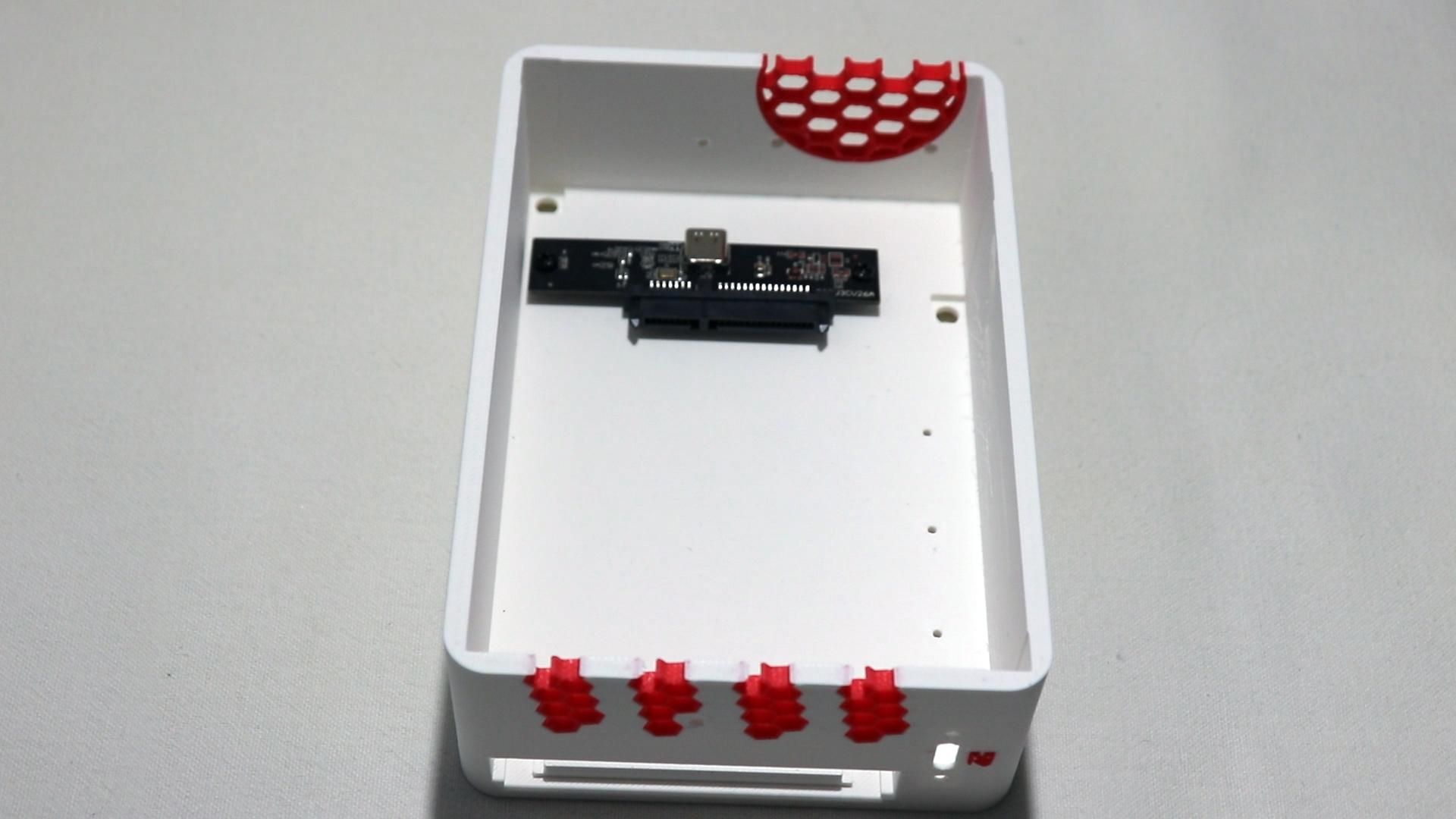
Now we can begin the actual installation!
First, take the SATA-to-USB adapter board and plug in the right-angle USB-C cable.
Then screw it into its mounting position in the bottom case using some appropriate small screws
Route the cable so it's free and doesn't interfere with the battery platform install.
Now install the USB-C breakout board into the slot at the back of the bottom case.
Secure it in place using 2 M2x12mm screws and nuts
Install the Battery Platform
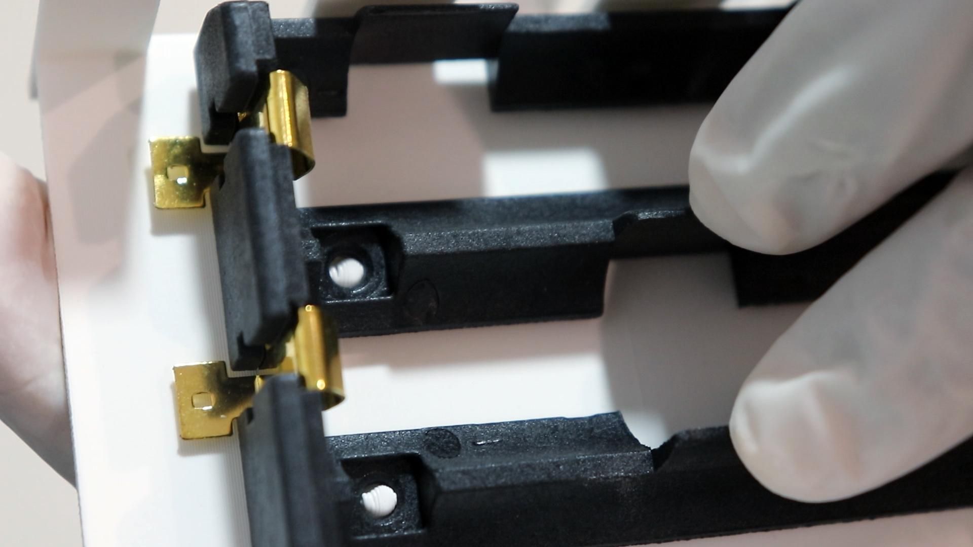
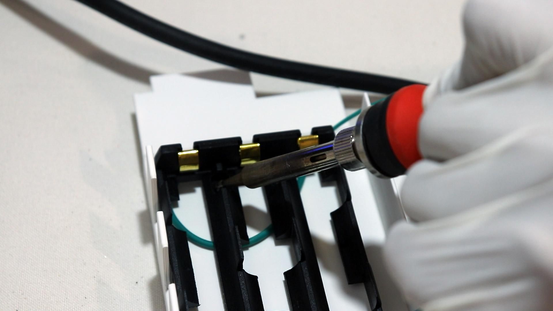
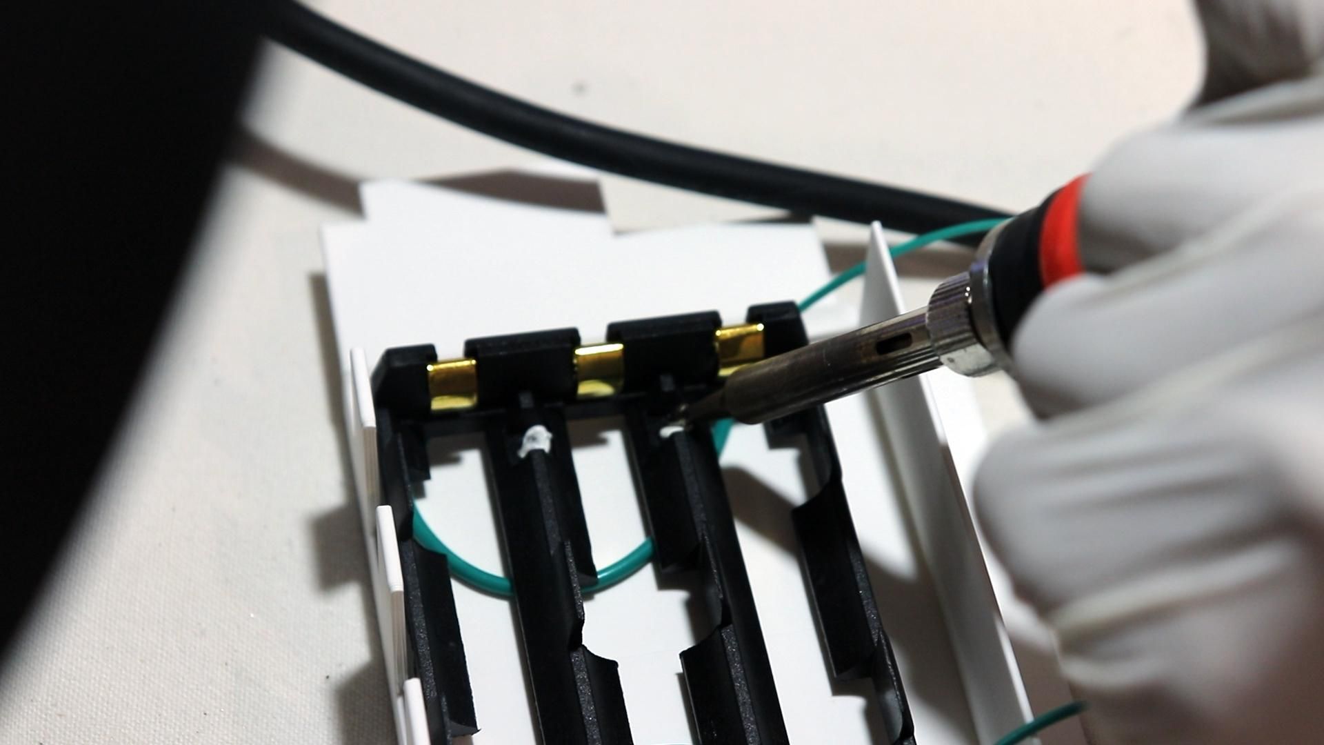
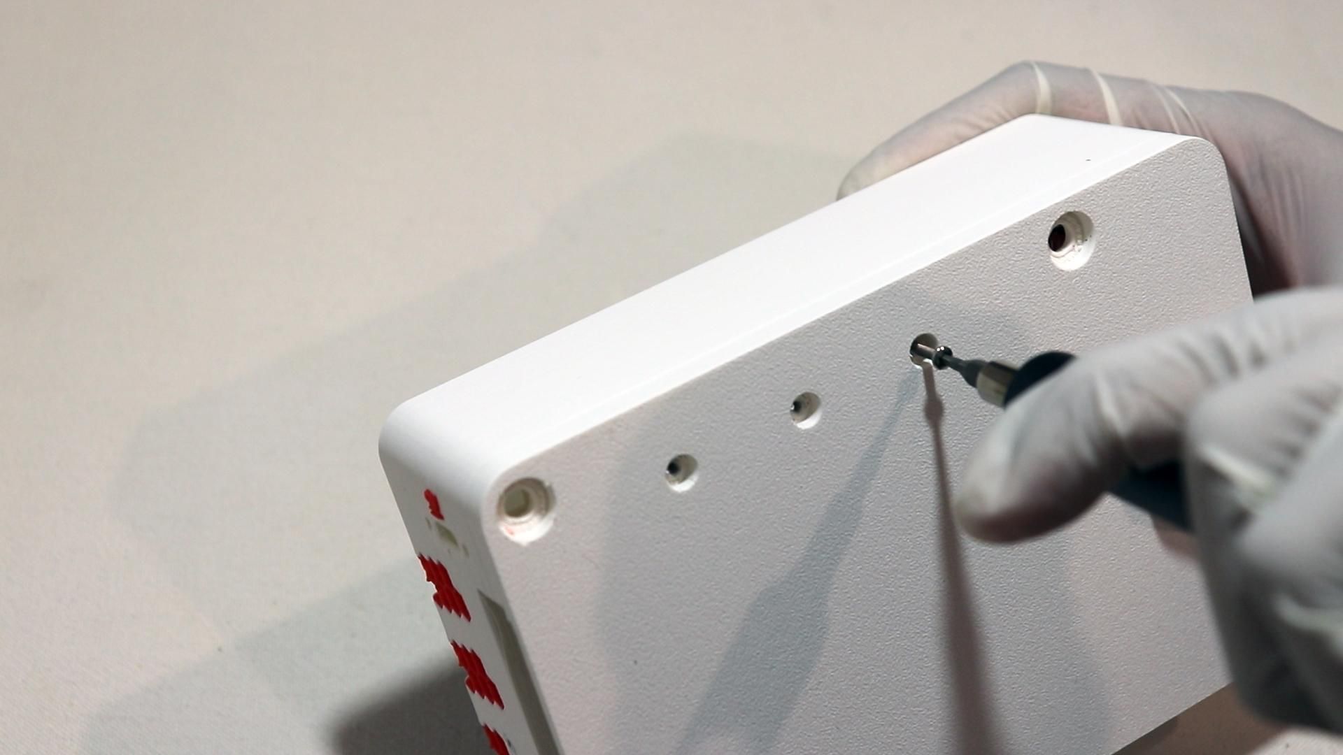
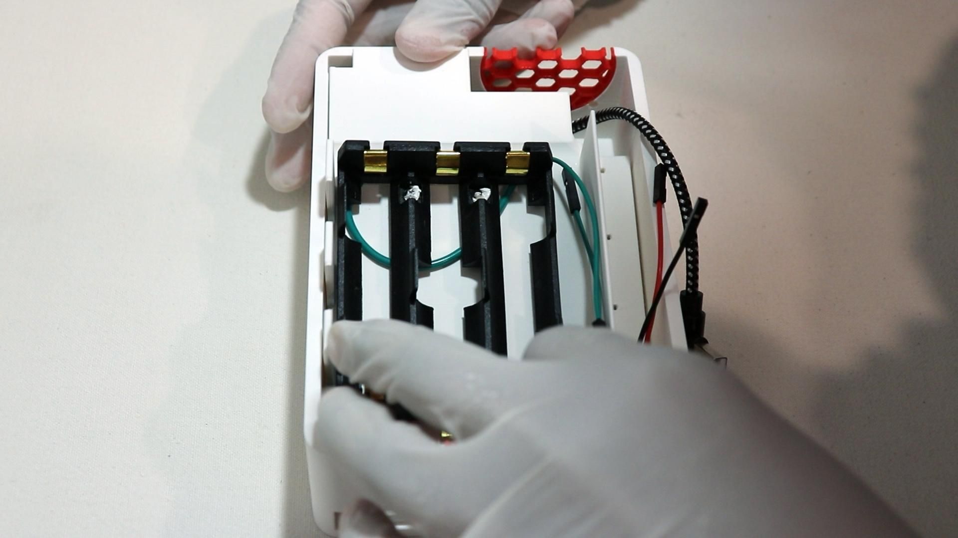
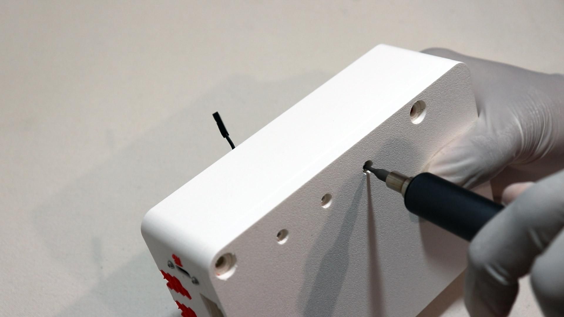
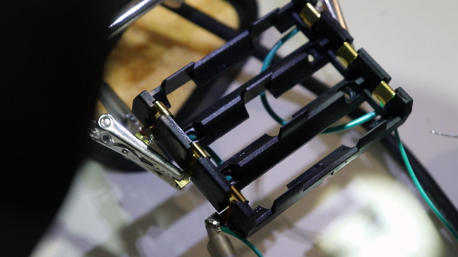
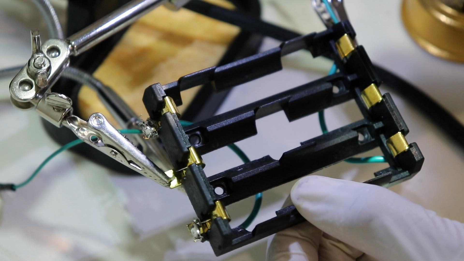
First, take the printed battery platform and your battery holder (the 3 slot 18650 holder).
Then, "weld" the holder to the platform: using a soldering iron on a low-to-medium heat setting, lightly melt the plastic at the installation holes between the battery holder and the battery platform. This is more effective and safe than using glue, in my opinion, since it greatly reduces the chance of the holder coming free and potentially shorting something in the case.
Also, if you haven't already, solder some wires onto the battery case, ensuring you are wiring in parallel.
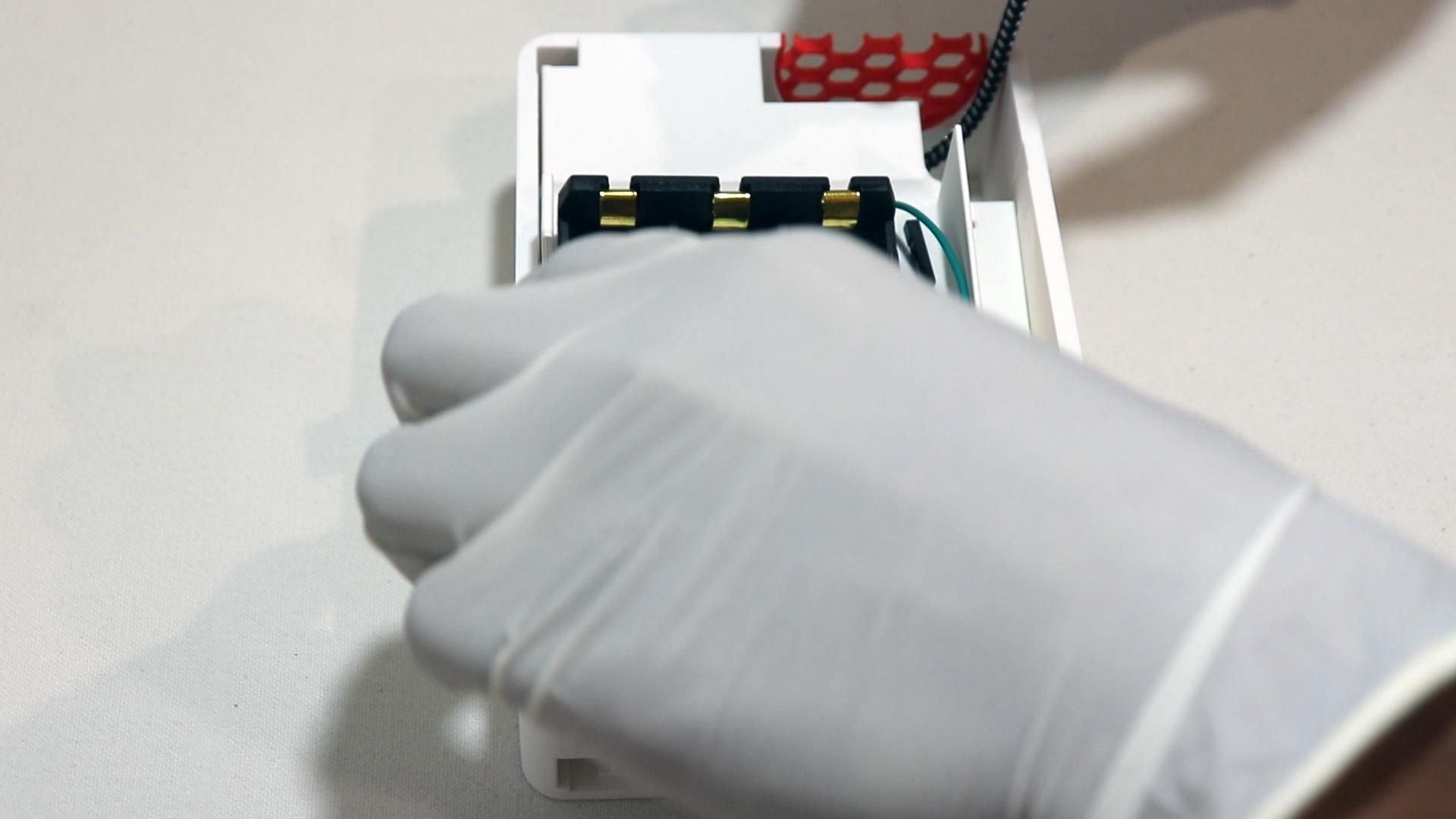
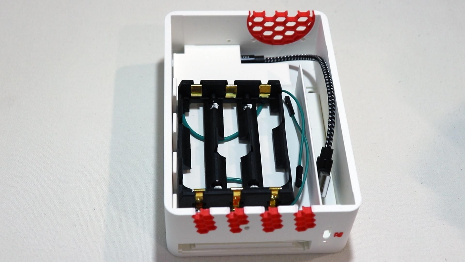
Once it has fused and fully cooled down, screw the battery platform into the base case. Place it over the SATA adapter and screw in from the bottom using 3x M2x12 screws.
Wiring
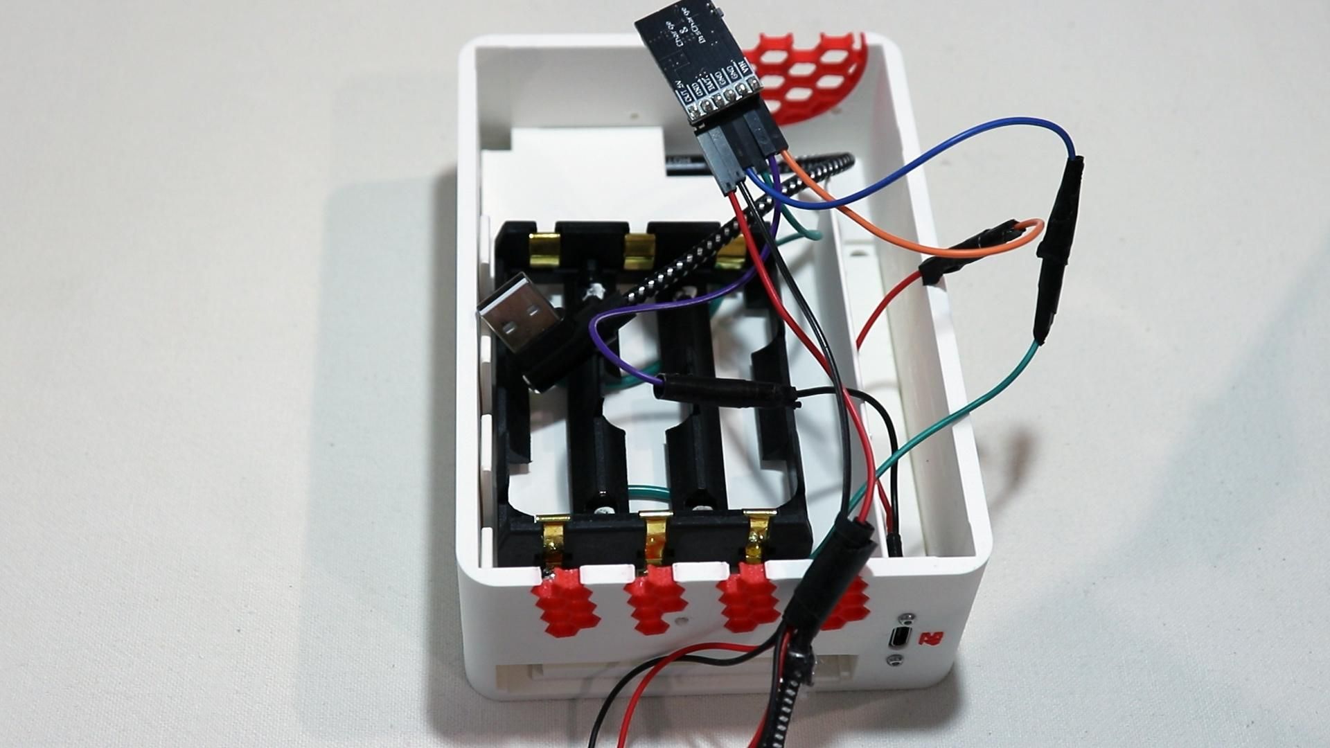
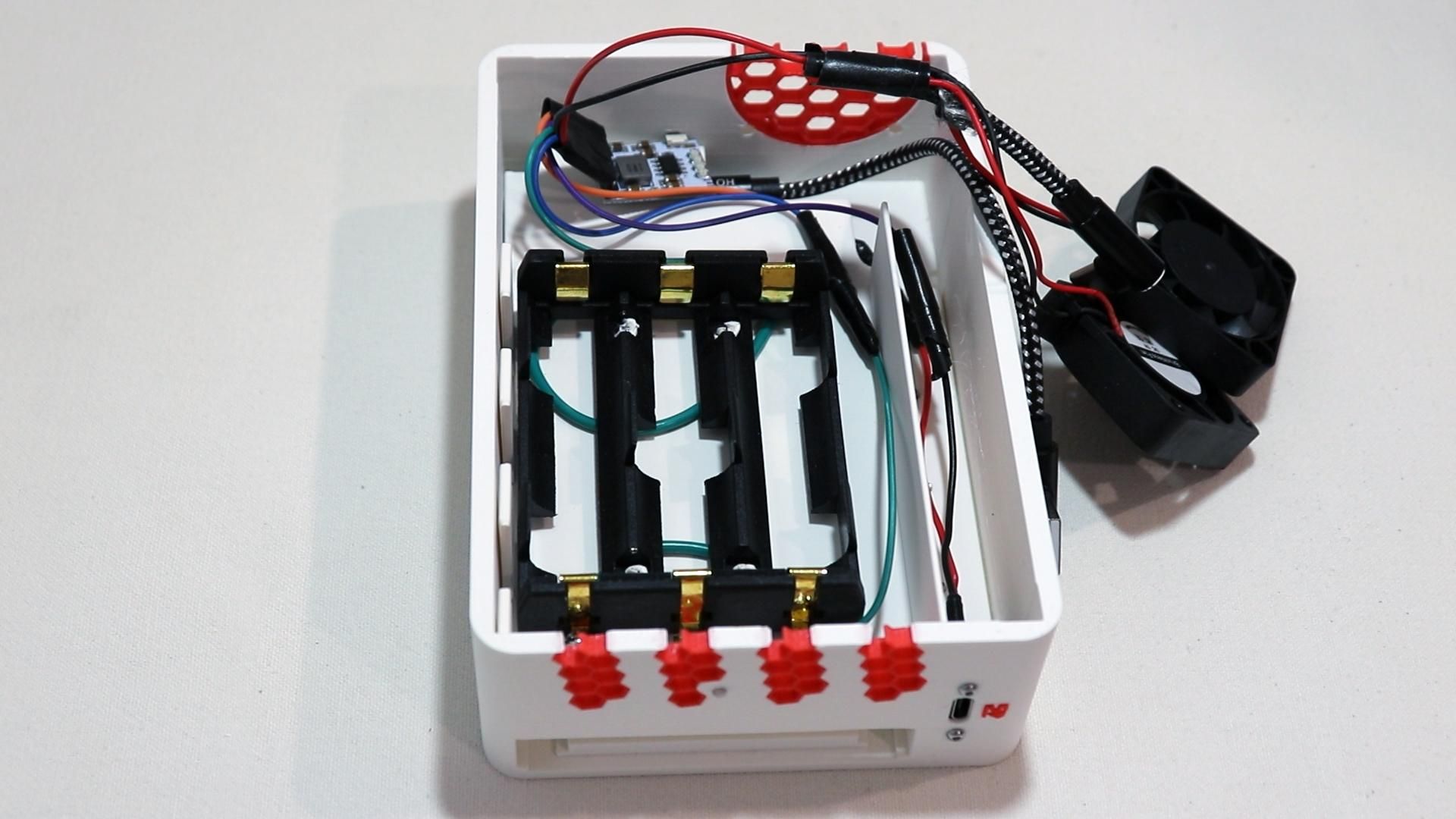
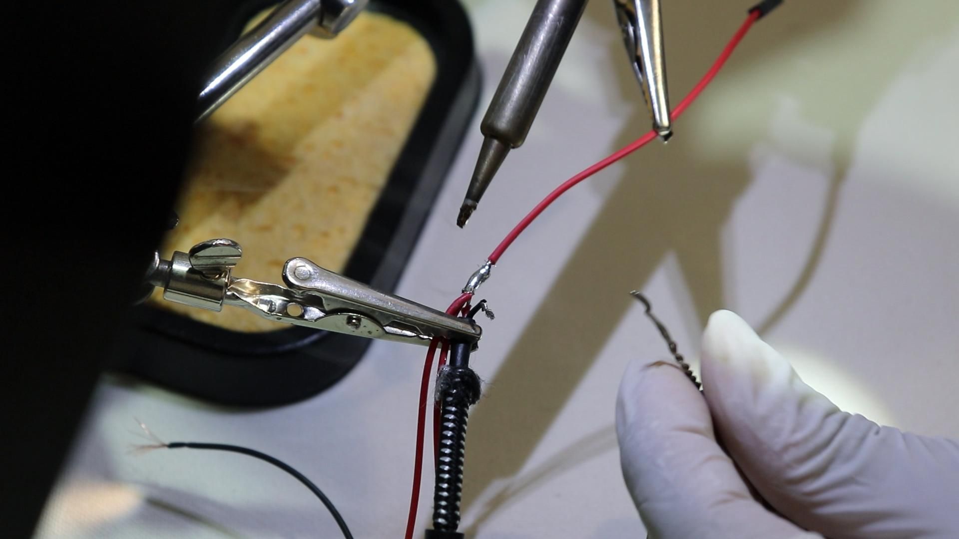
With most of the bottom case components mounted, it's time to do the first round of wiring.
The UPS module (MHCD42) has 6 relevant terminals which need to be connected up:
- BAT+ / BAT– → goes to the battery holder's positive/negative leads (ENSURE BATTERY IS IN PARALLEL - the UPS module will incorrectly charge your batteries if they are wired in series, causing damage or fire.)
- VIN / GND → this is the 5V input side. Wire it to the USB-C board's 5V and ground pins
- VOUT / GND → this is the regulated 5V output side — this is what powers everything downstream (Pi, fans).
Downstream components include the:
- Fan 1
- Fan 2
- End of a right-angle USB-C cable - to power the RPi safely.
Make sure to give every joint a tug test once cooled, and also consider a small dab of hot glue over each solder joint to ensure maximum reliability since this is a compact enclosure and the wires will be tucked in tight during final assembly.
Mount the UPS Module
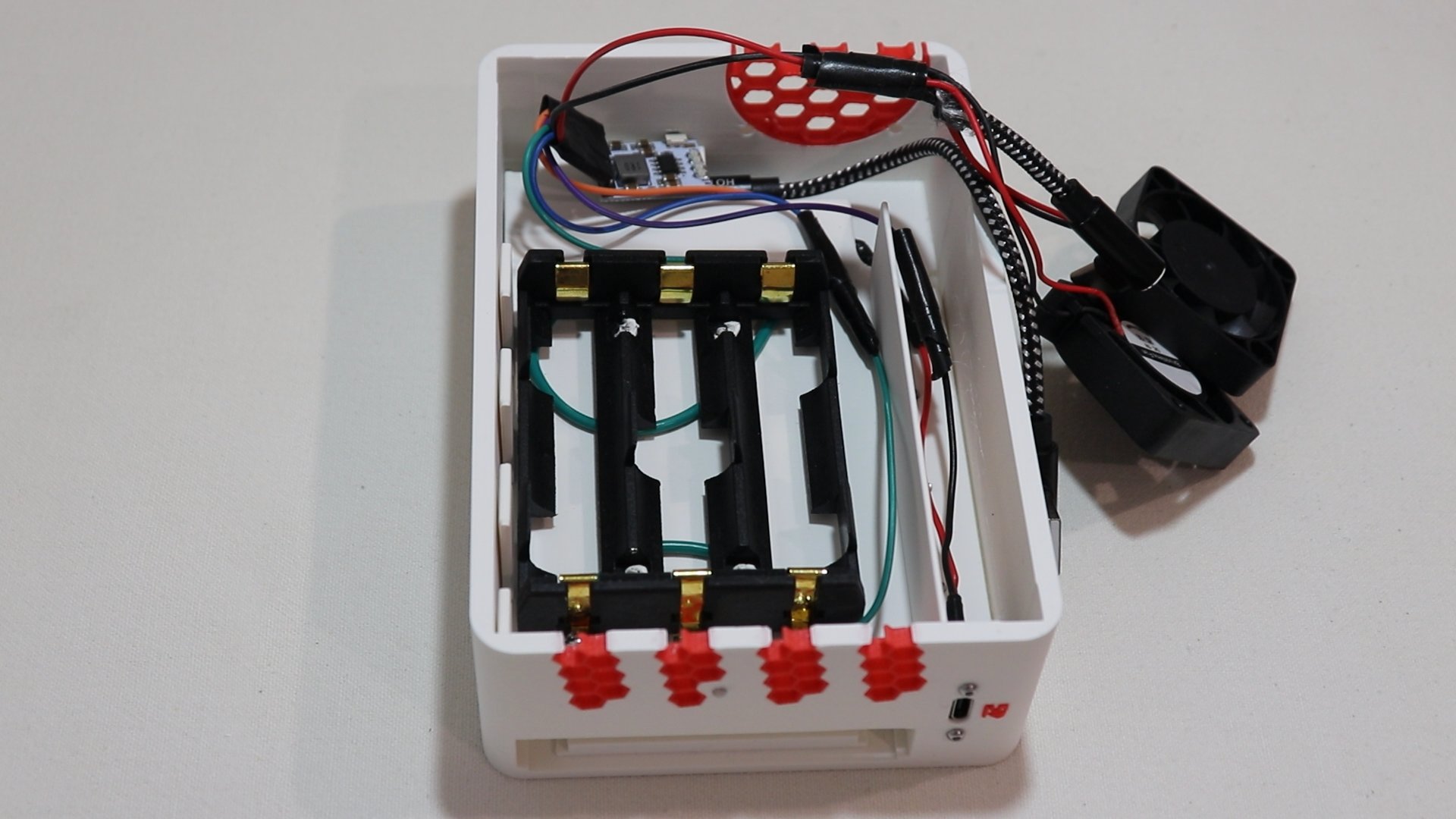
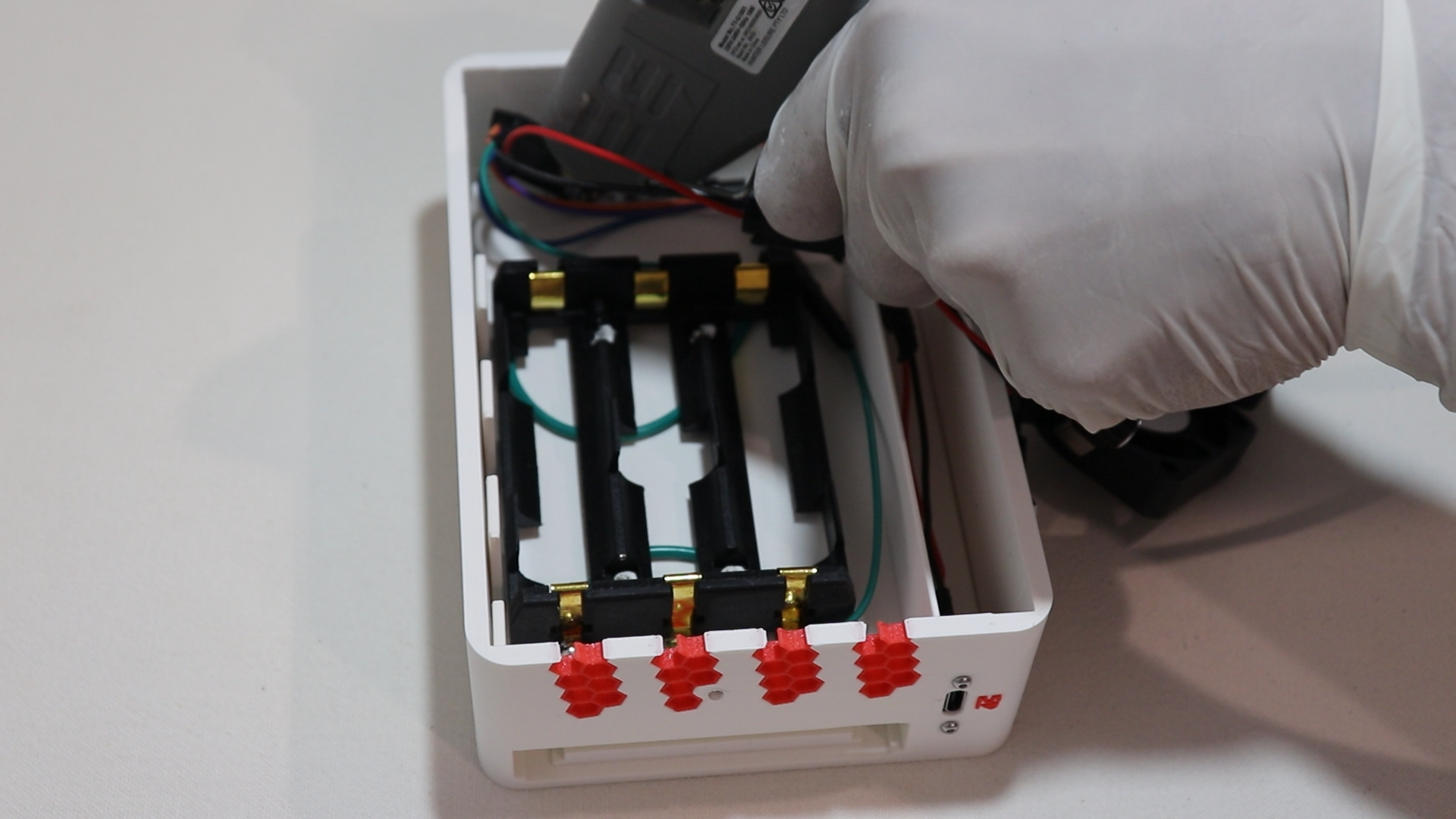
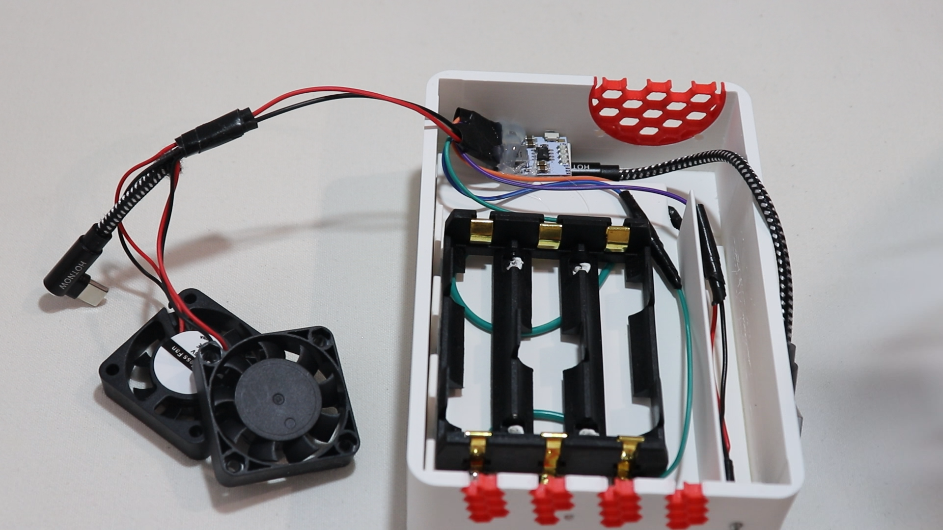
Now mount the UPS module.
Apply a small bead of hot glue to the back of the UPS (MHCD42 or better) module and press it into its place near the front of the case.
Before the glue fully solidifies, ensure that the UPS module's physical button lines up with the small poke-hole in the front of the case. You should be able to press the button through the hole with something like a pen tip or pin without struggle.
Install the First Fan
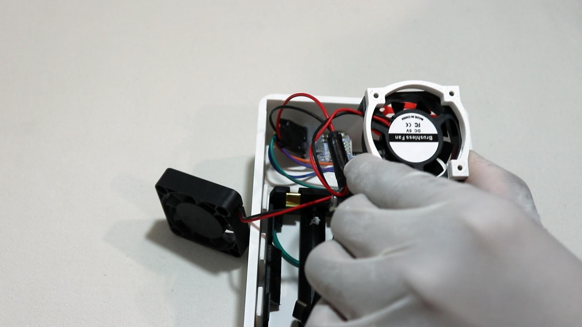
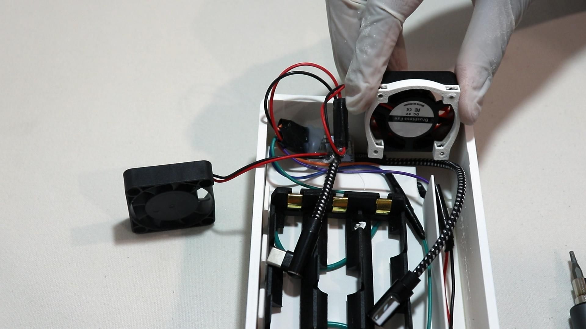
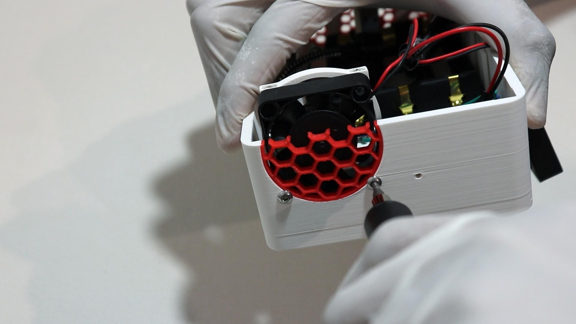
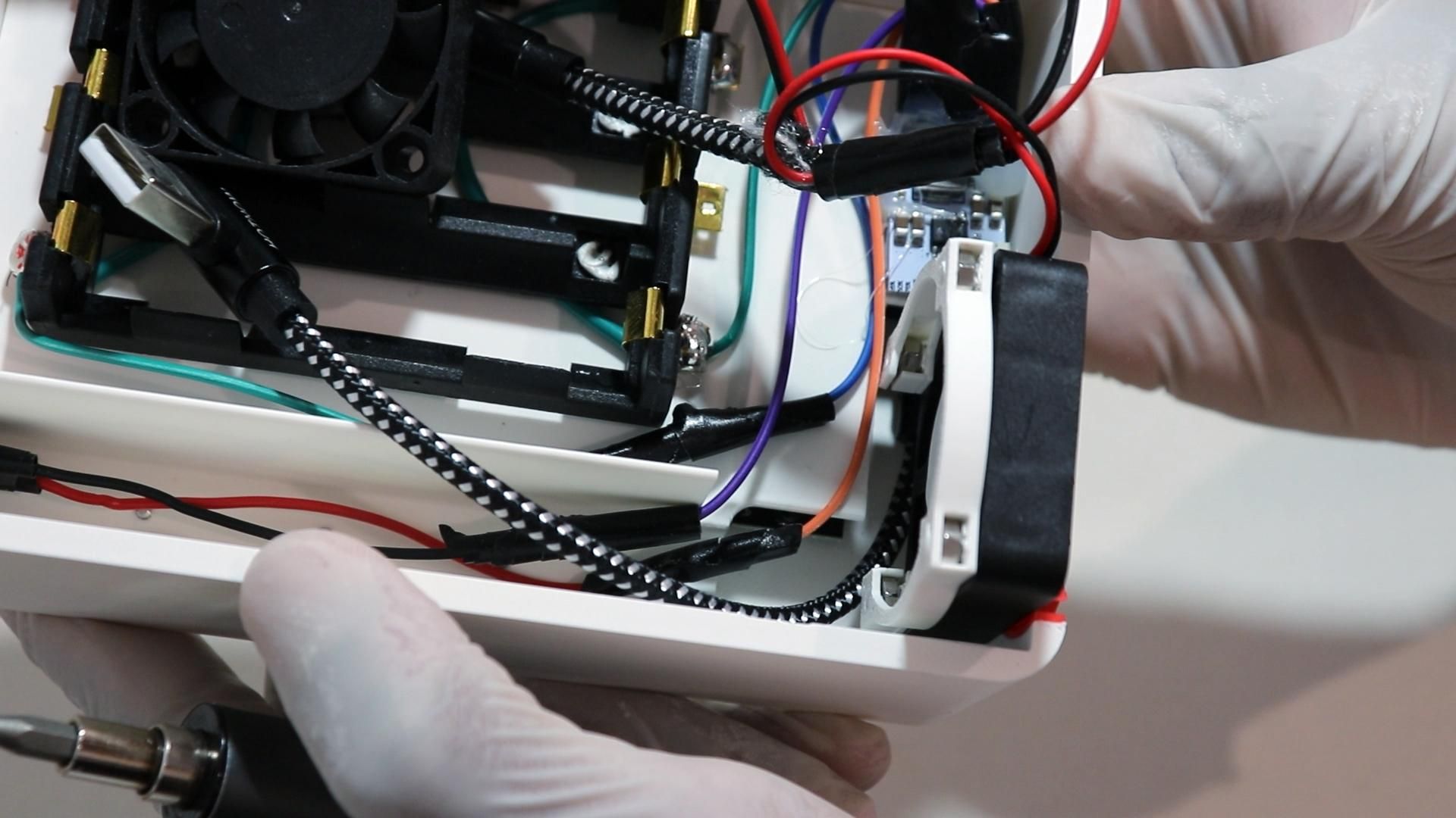
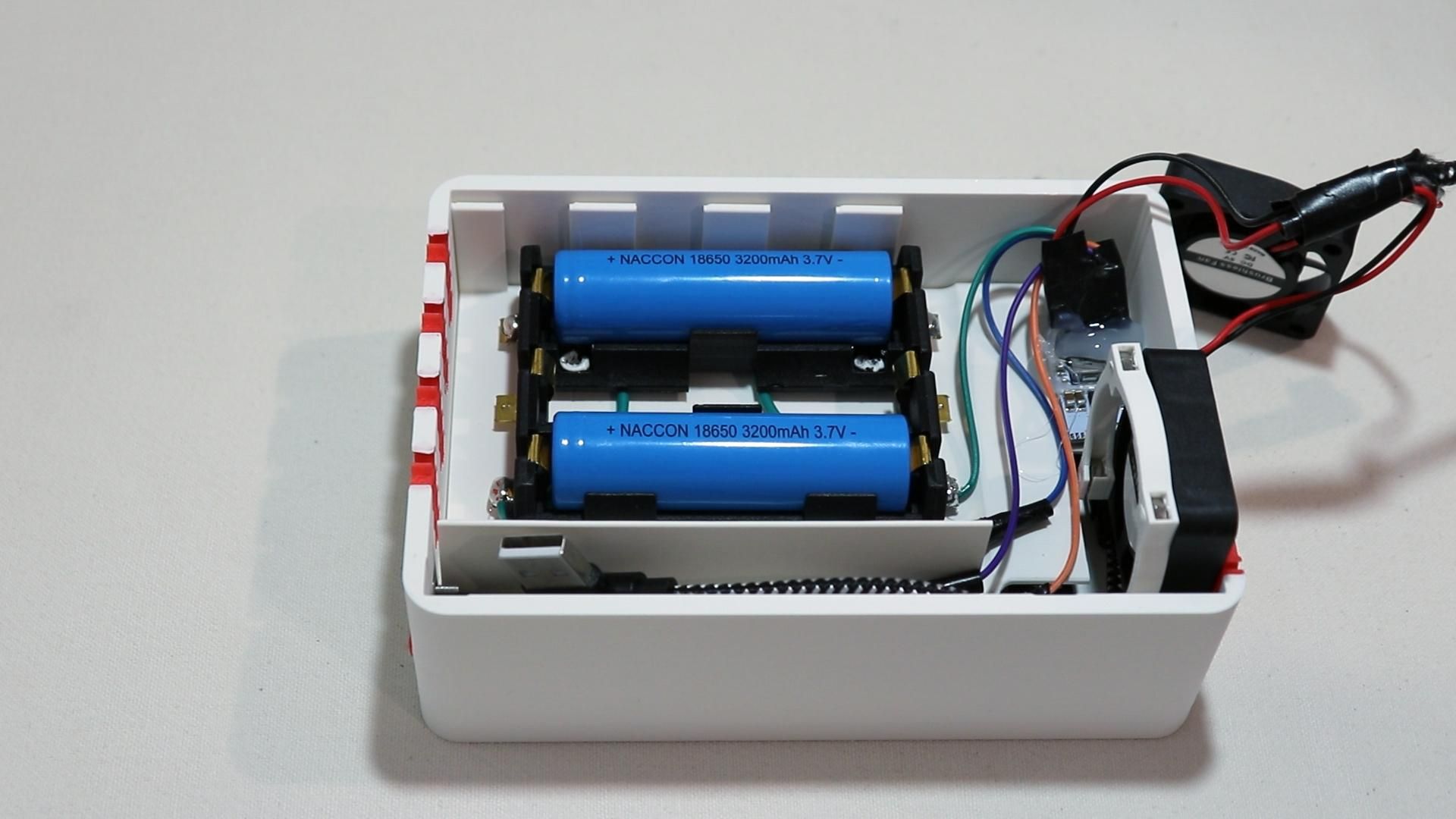
After wiring up the two fans, take one of the 4010 fans and the printed mounting plate.
Place nuts into the mounting plate first; there will be small cutouts on one side of the plate to place 4x M3 Nuts
Then, line the fan up against the mounting plate, then secure it using two M3x16 screws from the exterior of the case.
The remaining two screws at the top of the fan will be mounted when the top case goes on. (Hence the mounting plate)
You should also now insert your batteries into the battery holder since they will soon be inaccessible.
Install Top Case Components
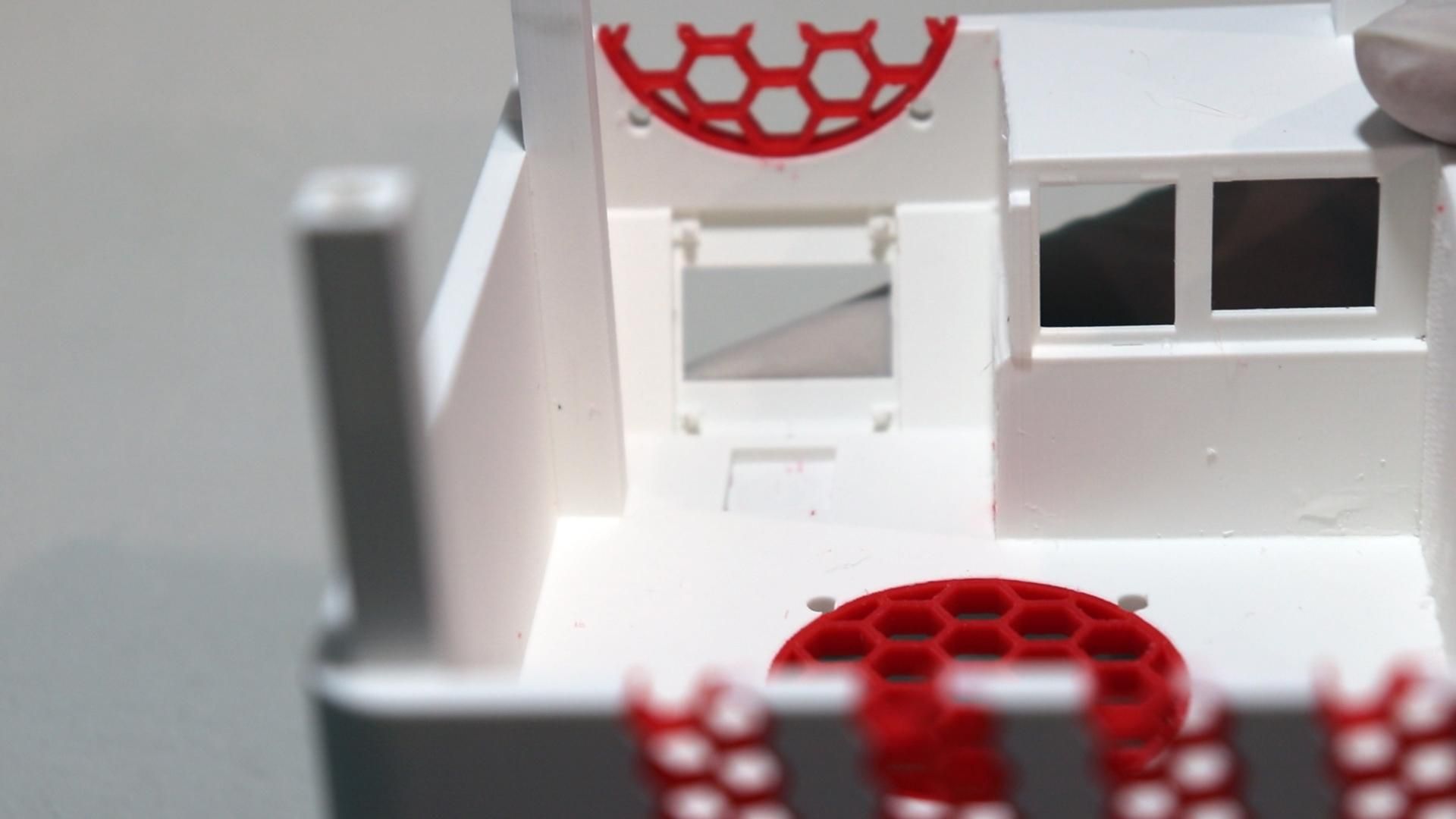
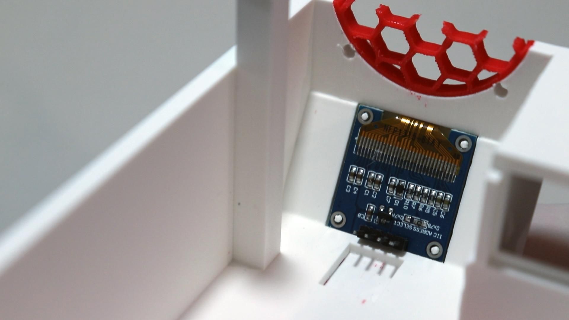
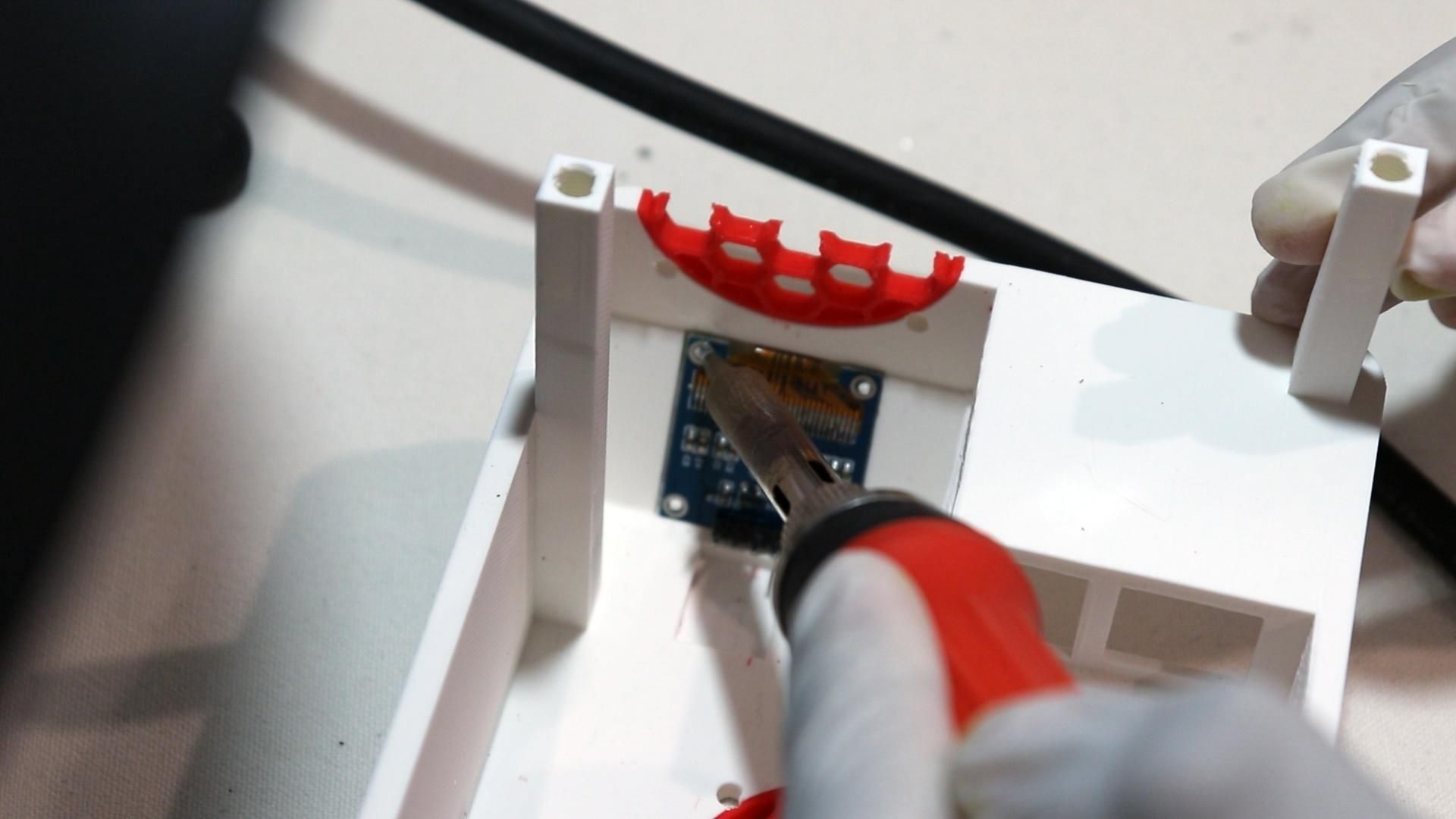
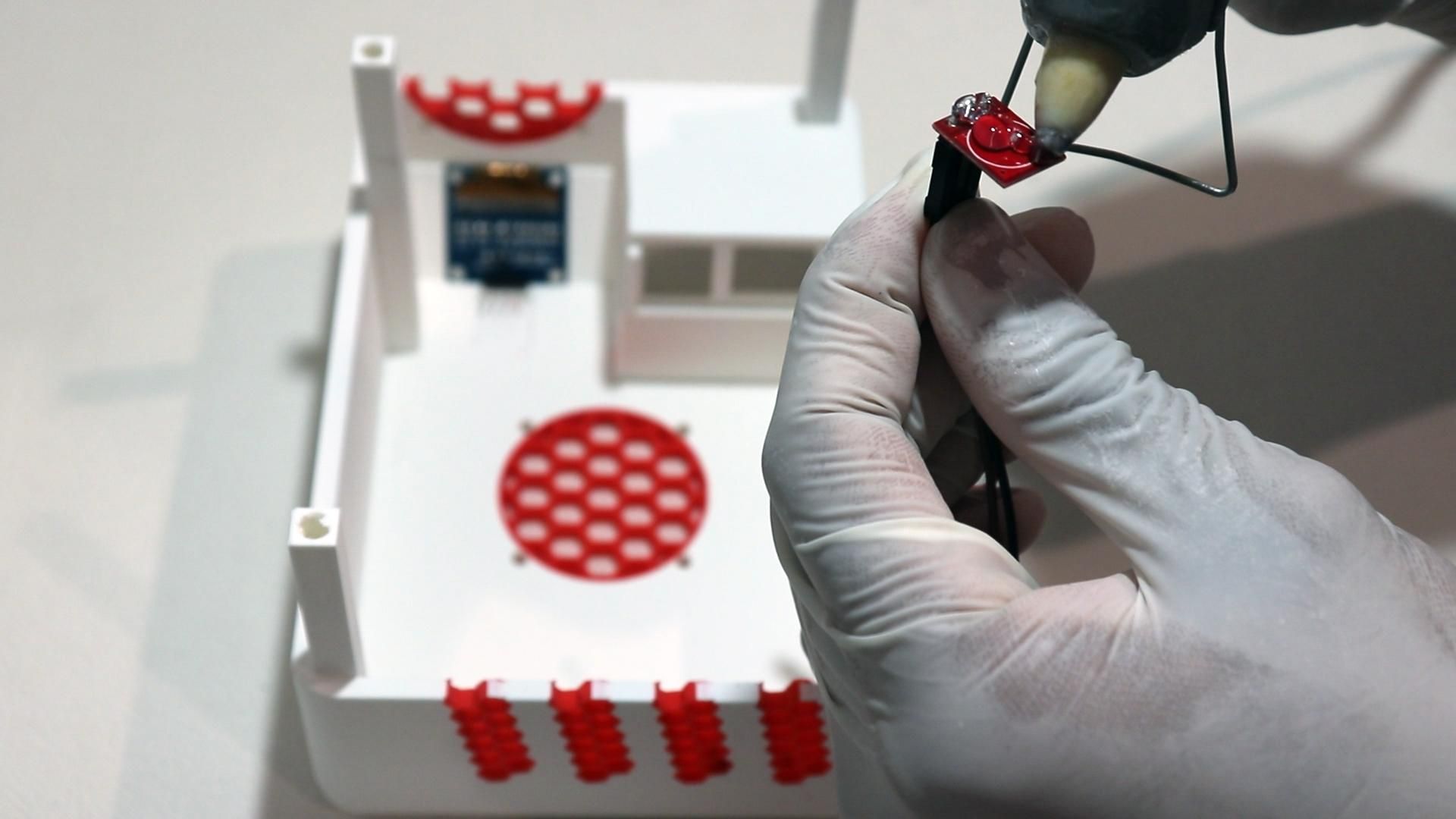
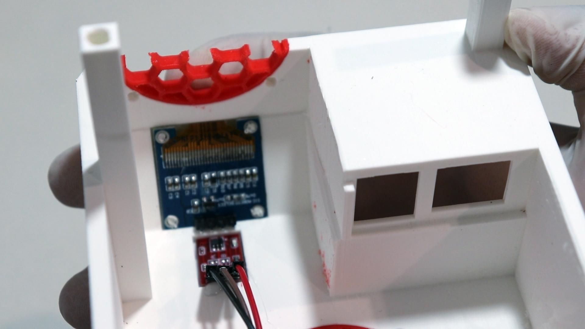
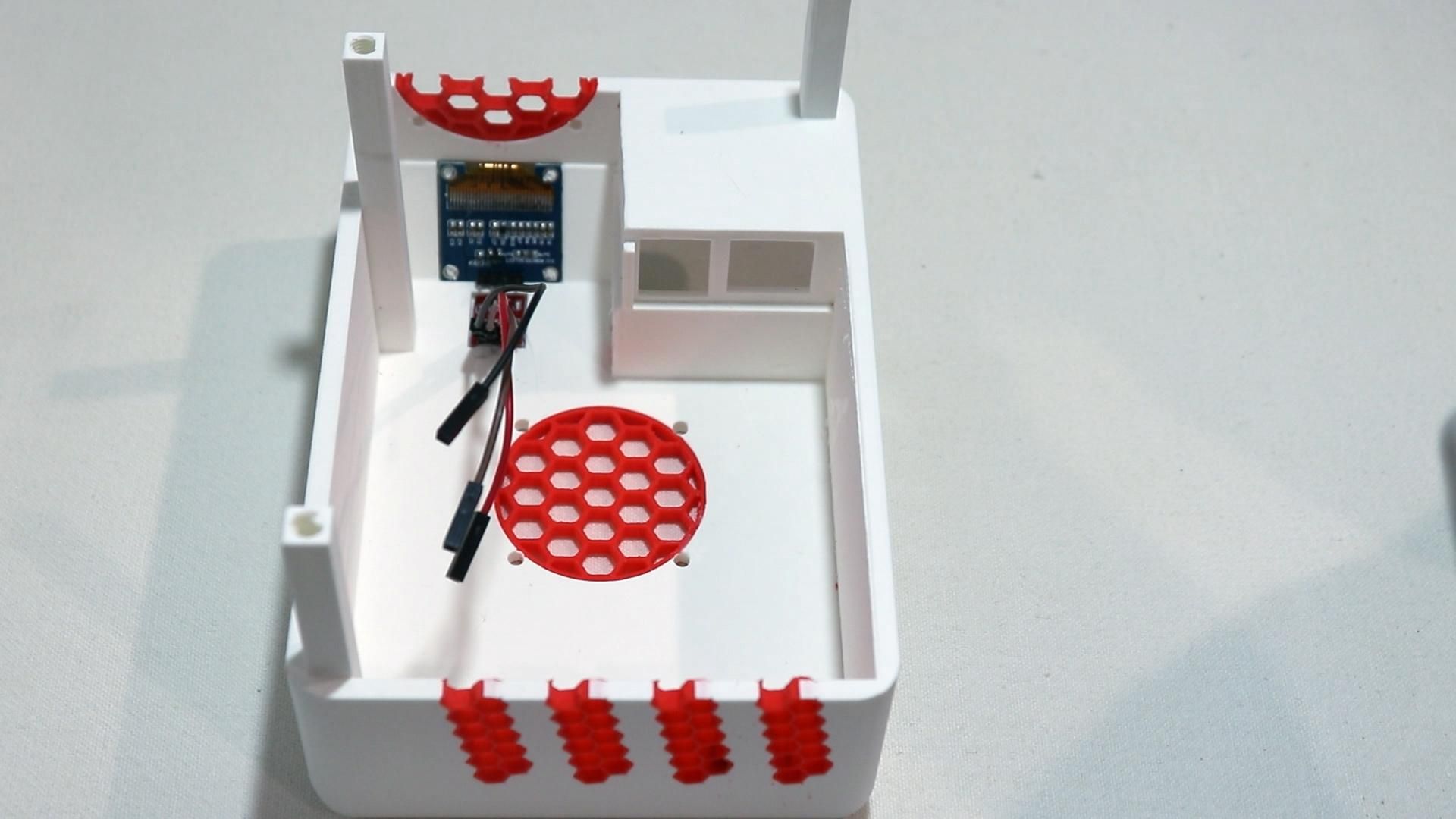
Taking a step back from the bottom half of the case, we'll begin working on the top half of the case.
To mount the OLED Display:
- Position the 0.96" I2C OLED display in its cutout on the top case
- Melt the plastic in the OLED's mounting holes to soften the plastic frame around the display and lock it in place.
- Ensure you are careful but quick with the soldering iron in order to only melt the plastic and not damage your display.
- Glue (or melt) the touch sensor (TTP223) module into its mounting spot (the touch sensor works through thin plastic, so it doesn't need a hole — just needs to be close to the surface).
- Optional: if you're adding an LED indicator board, glue (or melt) it into place above the cutouts for the front IO.
Leave the wiring for the OLED and touch sensor loose for now. You'll connect them later after the Pi is mounted.
Install the Raspberry Pi
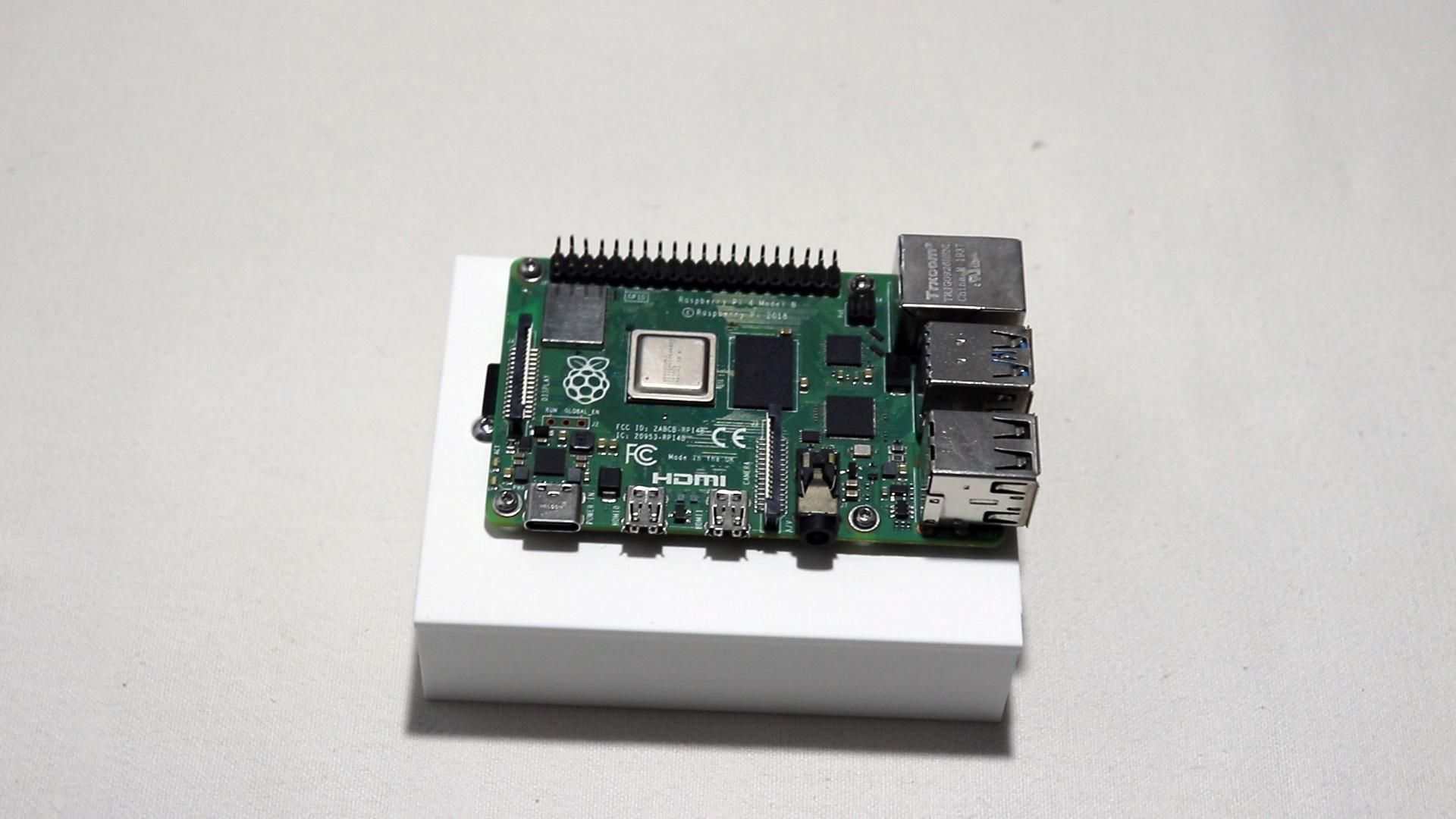
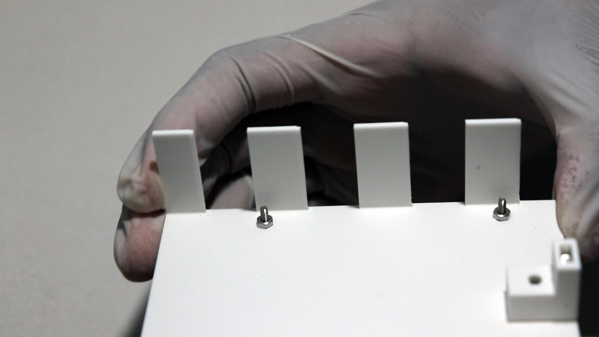
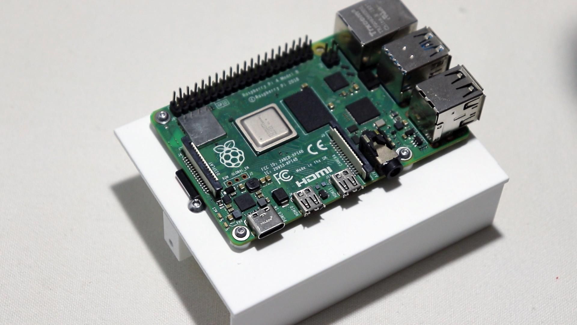
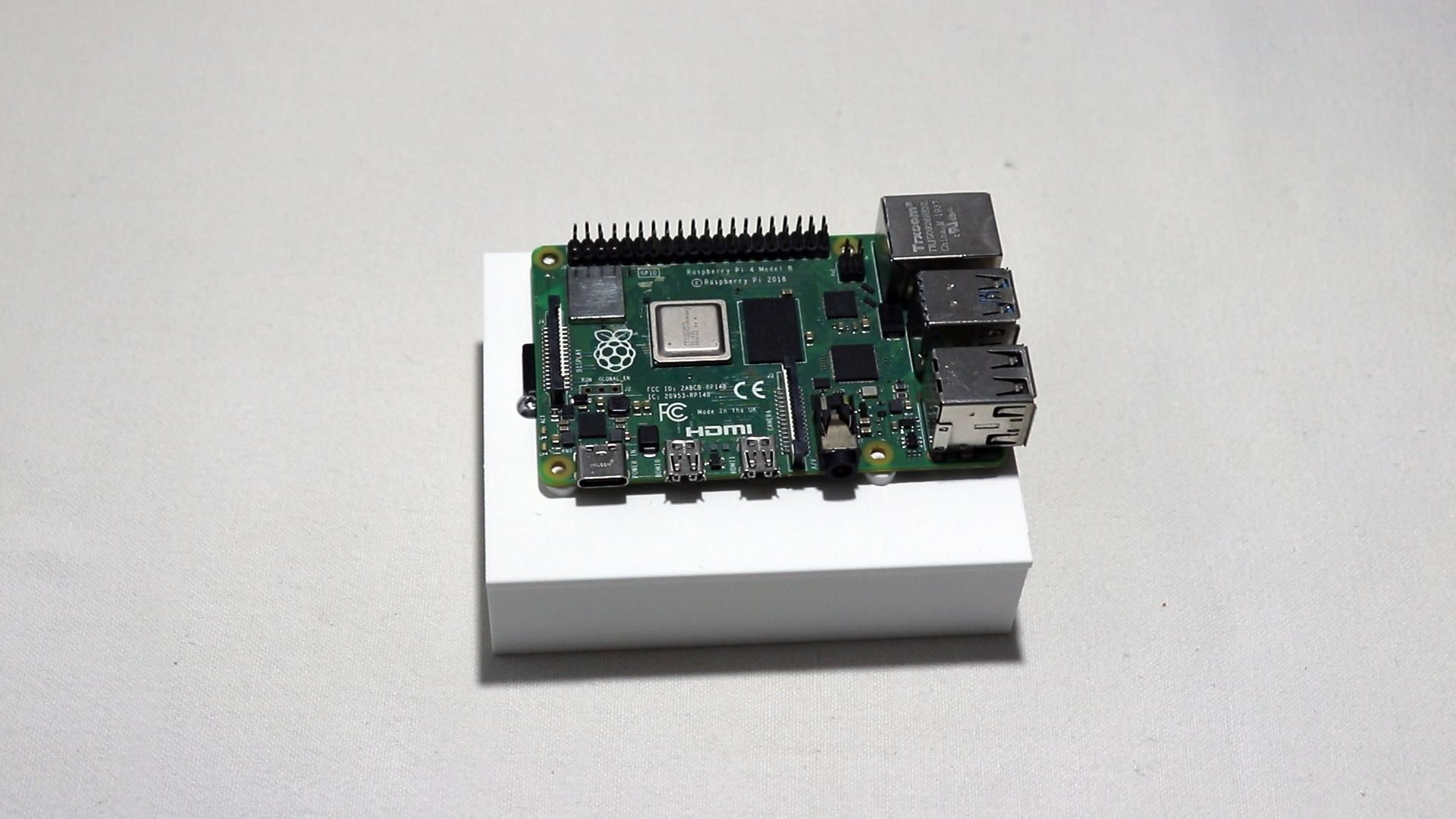
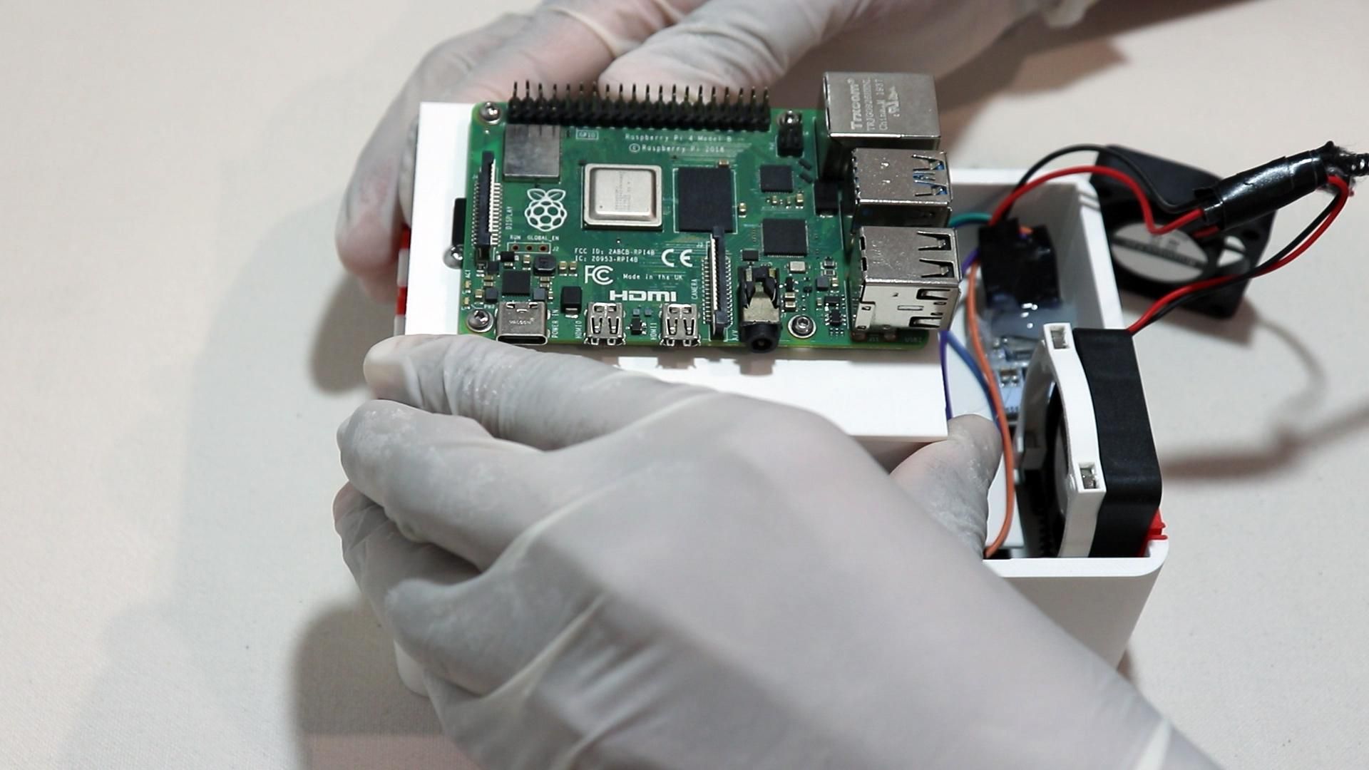
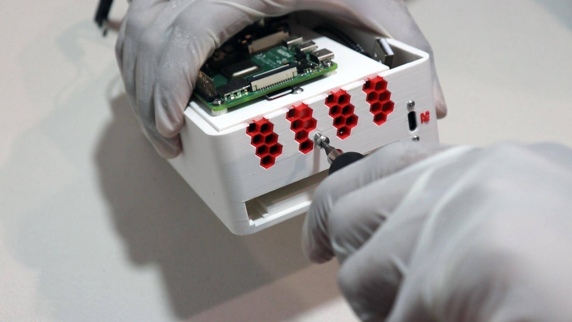
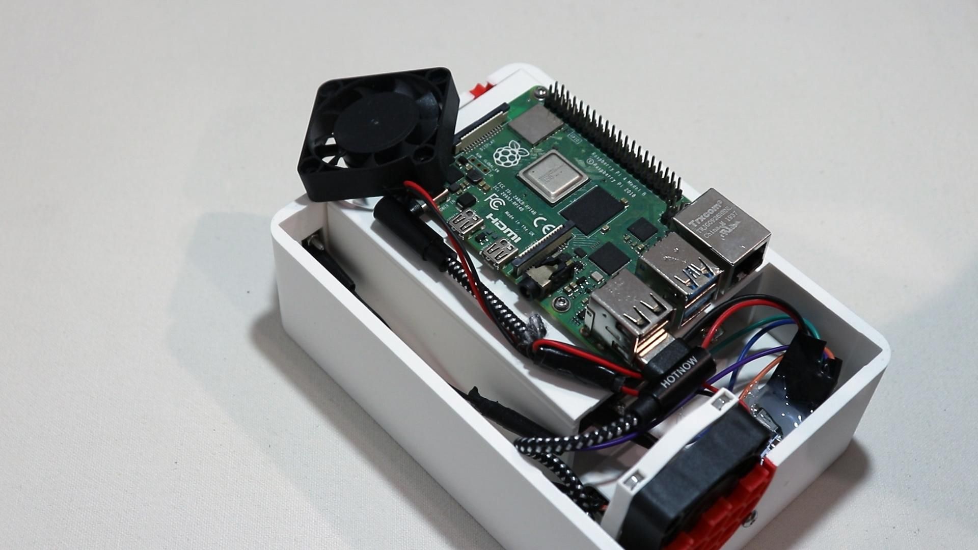
Now, we can begin securing the Pi.
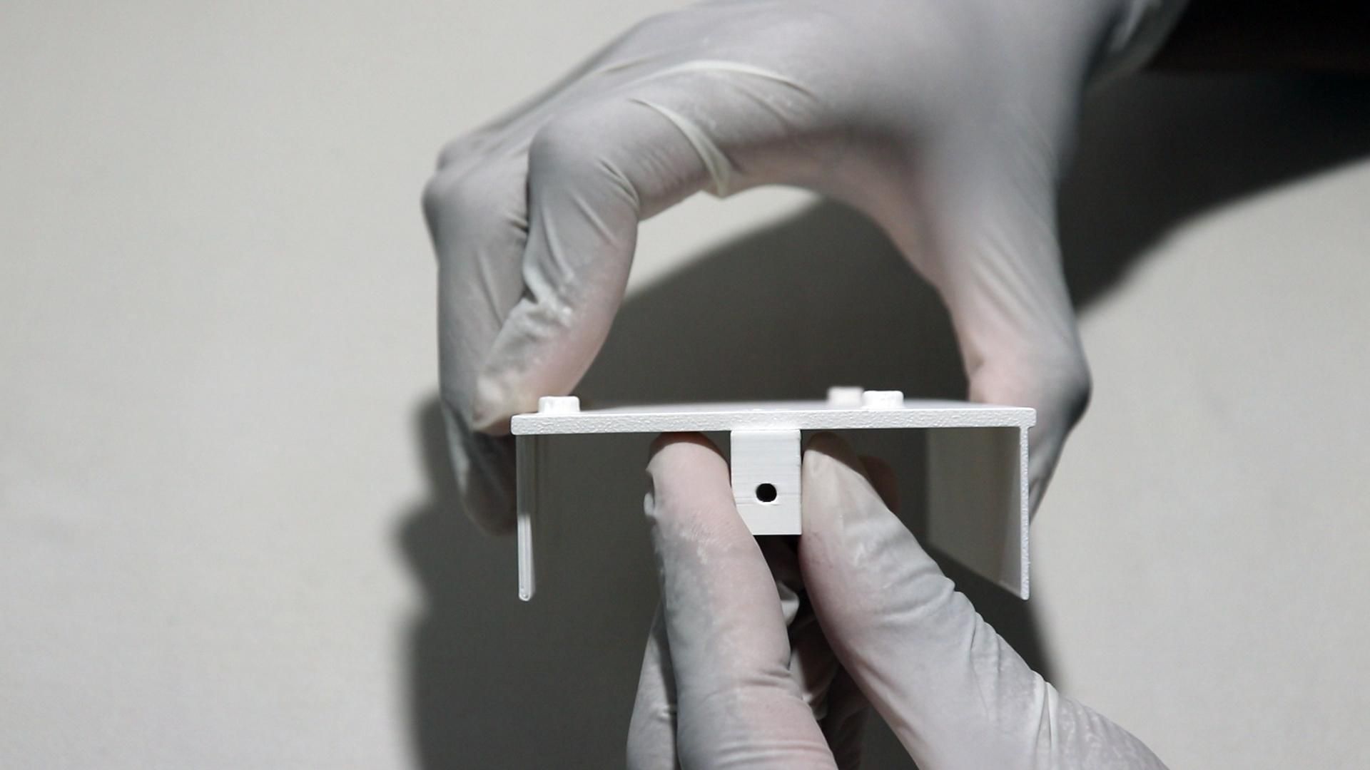
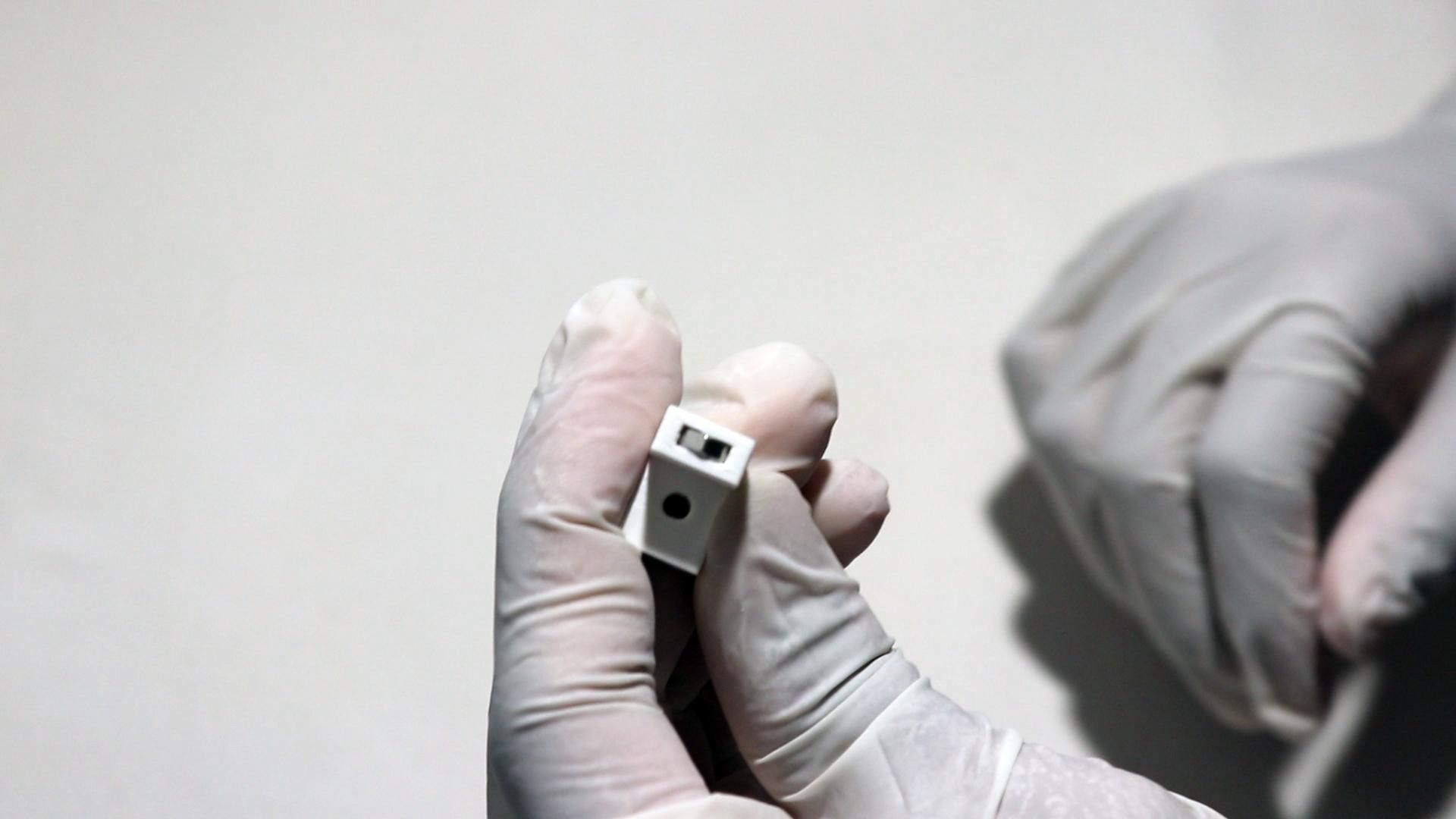
First, take the printed L-joint bracket and insert an M3 nut into both ends. Then screw the Pi mounting platform onto one side of the L-joint bracket using an M3x12 screw (this helps to make the build more stable).
Afterwards, mount the Raspberry Pi onto the Pi platform using M2x12 screws, washers, and nuts through the Pi's four corner mounting holes.
Place washers under your screws in order to protect your Raspberry Pi's PCB from scratches and excess pressure.
Then screw in the nuts, but ensure you don't over tighten them since the Pi's PCB can crack if you screw down too hard.
Finally, back to the bottom case, slide the Pi platform on top of the battery platform. The legs should line up perfectly since the case is designed so these two platforms stack.
Now, from the exterior of the bottom case, screw through the hole at the back with an M3x12 screw in order to secure the L-joint bracket (and subsequently the Pi platform) onto the platform.
Note: Make sure you flash and insert an SD card running 64-bit Raspberry Pi OS into your Pi before continuing!
The Battery System
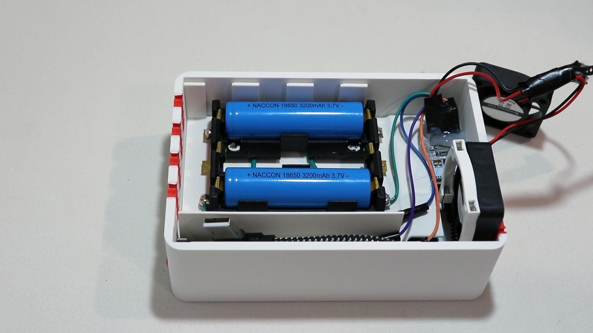
This is just an explanatory step on how versatile the UPS system is. Feel free to skip this step!
Cell configuration
This build uses up to 3x 3.7V 18650 Li-ion cells, wired in parallel (not series). This means that the pack outputs a nominal voltage of 3.7V, which is boosted by the UPS module's boost converter to a stable 5V VOUT, which the Raspberry Pi and fans can use.
Wiring batteries in parallel means the capacities add together while the voltage stays the same, which is exactly what I wanted when I paired a specifically designed 18650 UPS module with them. Parallel wiring also means more usable amp-hours (longer battery life), which is crucial in this build and allows the system to achieve long run times.
Idea
I originally built and am currently running this project with 2 cells in parallel; however, the battery holder, platform, and wiring are all prepared for 3 cells from the start.
This was a deliberate design choice since, rather than committing to a fixed battery capacity and needing a redesign later if my needs changed, the mechanical platform already supports dropping in a third battery straight into the holder without any changes needing to be made. The UPS module itself views the 3.7V batteries as one large battery when wired in parallel, so if you're building this fresh, I'd recommend just filling in all 3 slots from day one!
Battery Life:
Now, I claimed in my title that the UPS can support around 5+ hours of runtime.... and that's actually inaccurate.
My current setup is two 3200mAh 18650 batteries; however, with a maximum support of 3, I could technically have a total of 9600mAh of capacity. According to my tests, the Raspberry Pi 4 (4GB) version + 2xFans + SSD only draws around 750mA from the battery pack while at low loads.
This means that, theoretically speaking, the maximum runtime supported by the battery pack within the Lifepod is: 9600mAh/750mA = 12.8 Hours!
While of course, this will be lower in real-world testing due to component inefficiencies, variable loads, temperatures and more, if we apply a conservative 40% energy waste/use in higher loads, we still get around 7 hours of battery life, a lot more than the 5 hours I claimed!
Why did I claim 5 hours though? Well, that's just how long the battery pack would last when the Pi, fans, and SSD are under medium/heavy loads and drawing about ~2A current from the battery.
This just goes to show how versatile having 18650 batteries inside the Lifepod is.
The UPS module:
I used an MHCD42 UPS module sourced from AliExpress because it's relatively inexpensive (~5$) and readily available (100+ listings).
While it does do its core job properly, like charging the batteries from VIN and outputting a stable 5V boost on VOUT, it does have its issues. It occasionally has voltage drops (4.7V rather than 5V) on the VOUT pin, which can cause potential crashes on the Raspberry Pi, or even worse, data corruption on your SSD/ SD Card.
Because of this, if you're going to make this project today, I'd strongly recommend you find a higher quality UPS module from a reputable source, rather than a random AliExpress store. You'll definitely want one with built-in safety features like proper over-discharge / over-charge cut-off protection, balanced charging (if you decide to wire in series) and strong max output currents.
General 18650 safety notes
Never mix batteries or cells of significantly different ages, wear or capacity in the same parallel pack. A weak cell in a parallel bank can be forced to accept charge current from healthier cells, which can cause stress and damage.
Always use protected cells or a UPS/BMS module with its own protection circuitry built-in. It's a terrible idea to run bare, unprotected cells with no cutoff!
Keep the battery pack physically secured (which is why plastic welding was done). The 18650 cells are the last thing you want rattling around next to a heat-generating Raspberry Pi and UPS module.
Give the battery pack ventilation. This is the reason why there are two fans in different positions to move air throughout the case rather than just cooling the Pi's CPU.
Wiring (Again)
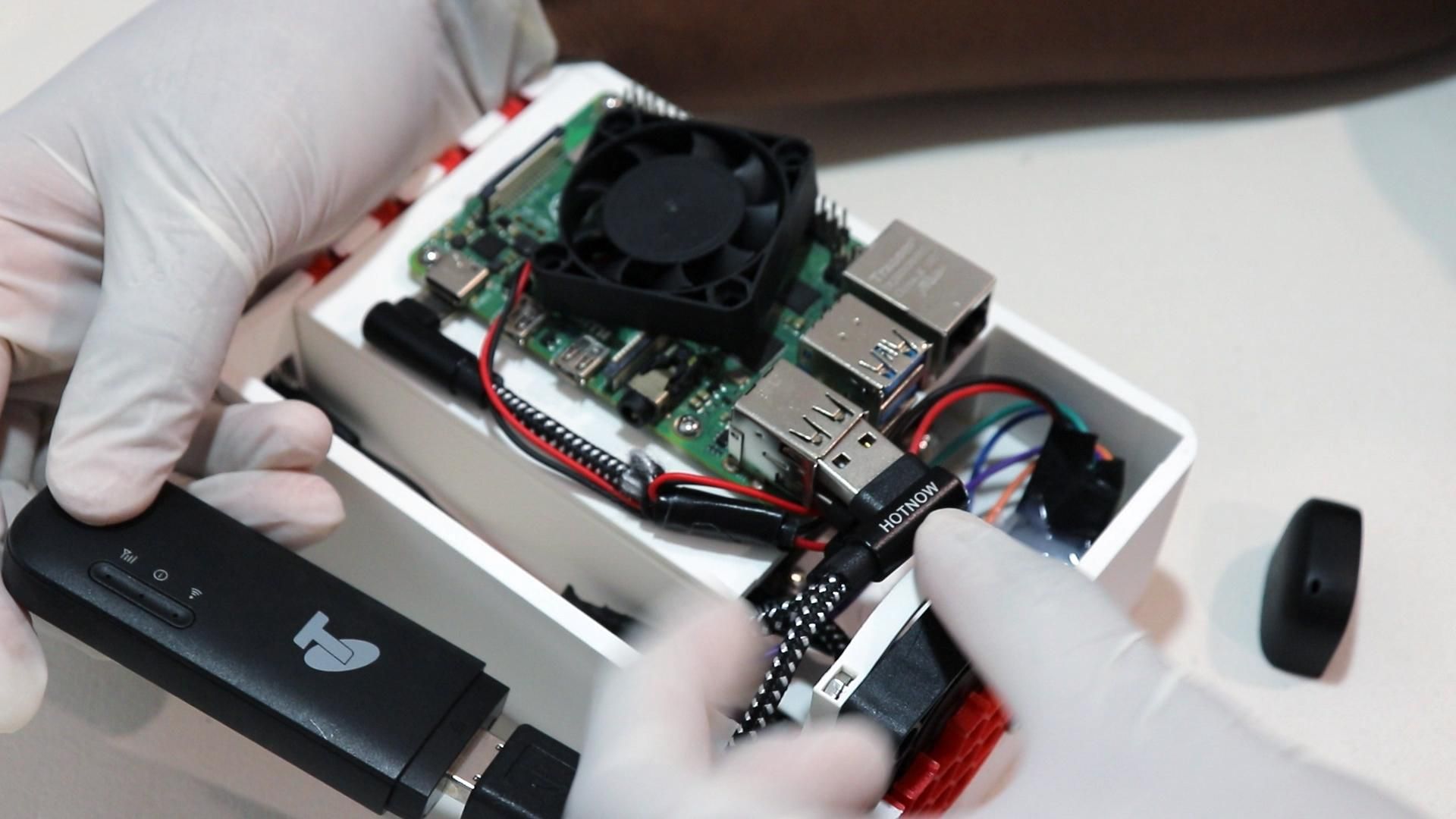
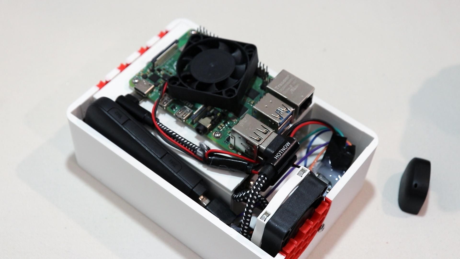
With the Pi now mounted and the OLED & touch sensor hanging loose from the top case, it's time to connect everything to the Pi's GPIO header.
Note: I unfortunately wasn't able to take quality photos of the top case wiring due to how constricted it was
Wiring the OLED:
OLED pin - > Pi GPIO pin
VCCPin 1 -> (3.3V)
GND - > Pin 6 (GND)
SDA - > Pin 3 (GPIO2 / SDA1)
SCL - >Pin 5 (GPIO3 / SCL1)
Wiring the touch sensor:
Touch sensor pin -> Pi GPIO pin
VCC -> Any available 3.3V VCC
GND -> Any available GND
pinOUT (signal) -> Pin 11 (GPIO17)
Wiring the LED:
LED Pin -> Pi GPIO pin
VCC -> Any available 3.3V VCC
GND -> Any available GND
DataIn(signal) -> Pin 12 (GPIO18)
LTE dongle: It's also now time to connect the USB LTE dongle to the short USB extension cable and then to the RPi's USB port.
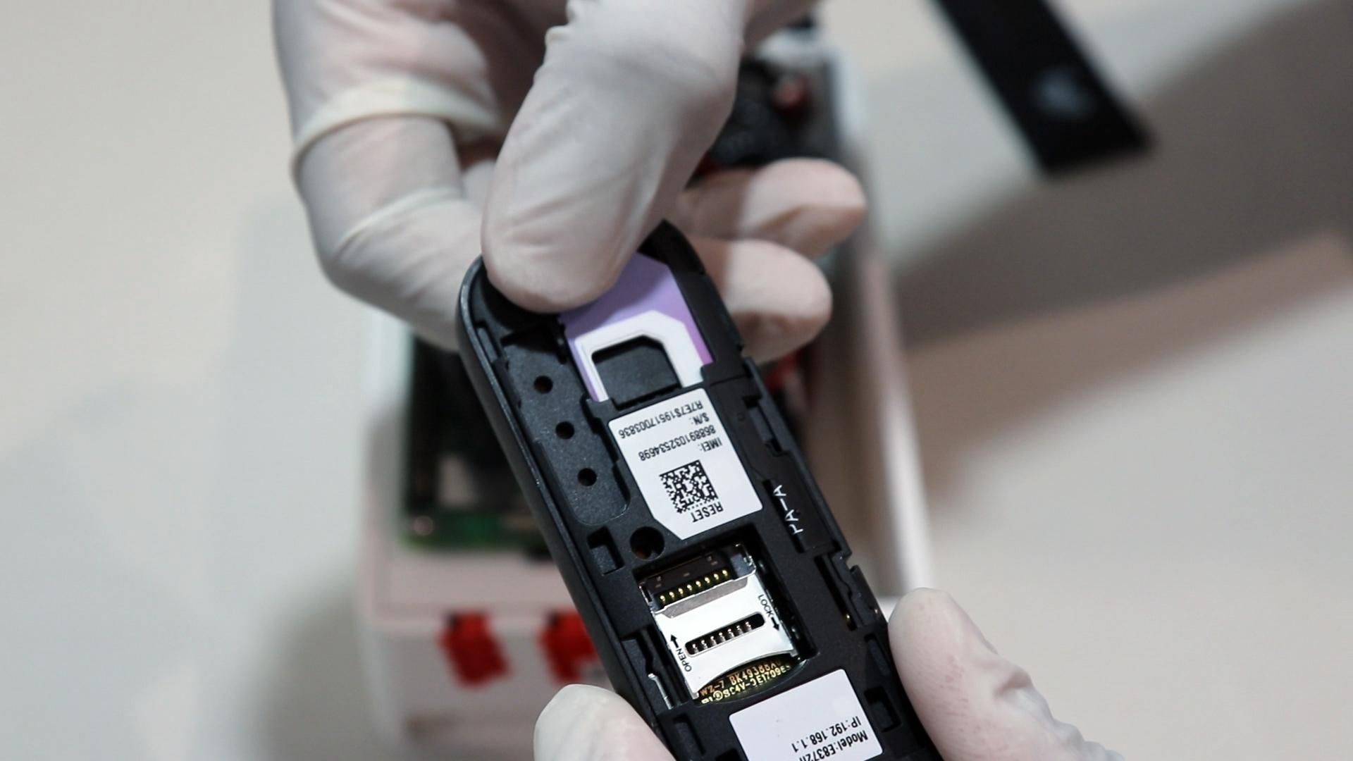
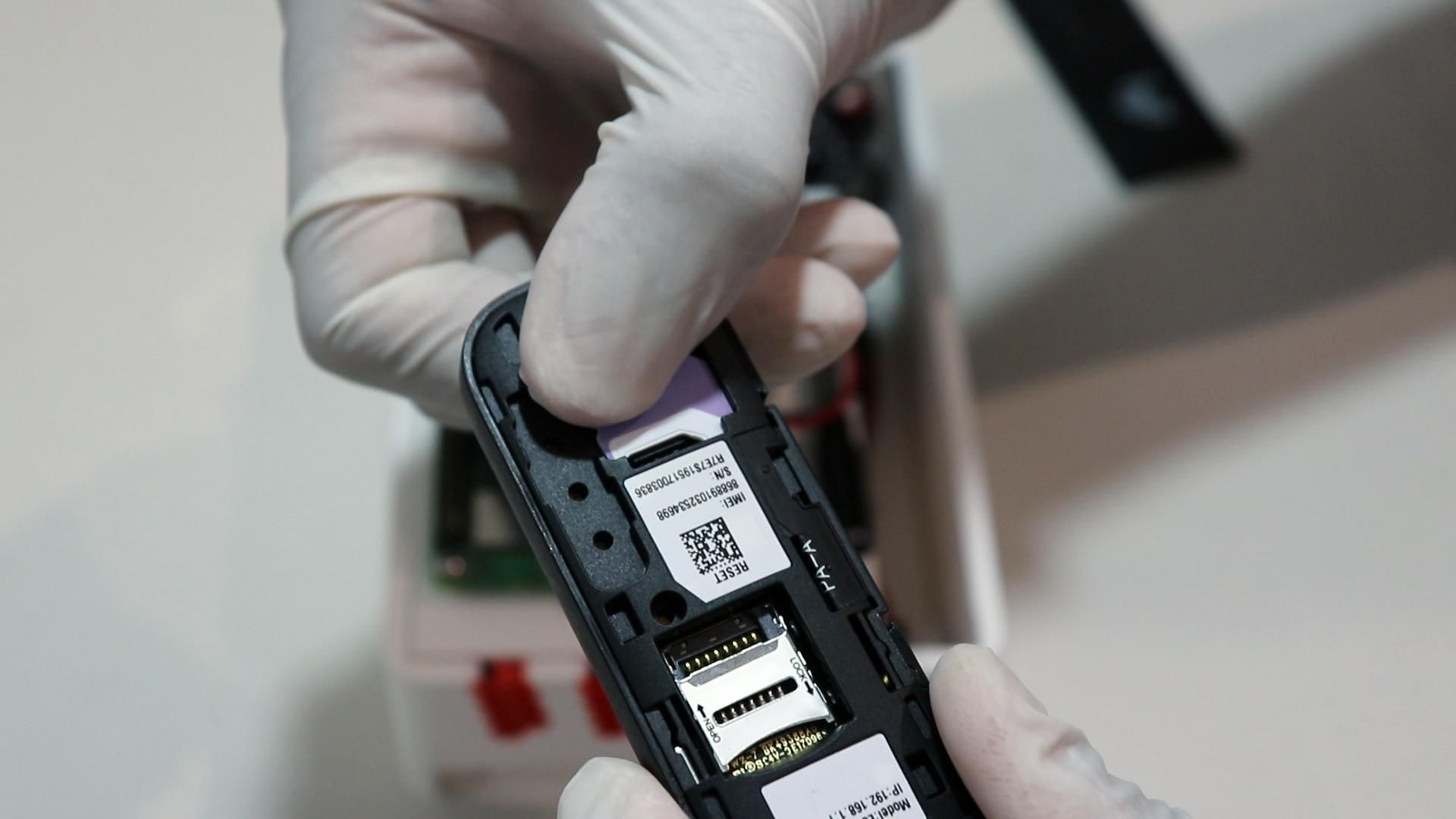
Make sure you insert a SIM card into the dongle prior to installing it!
Mount the Second Fan
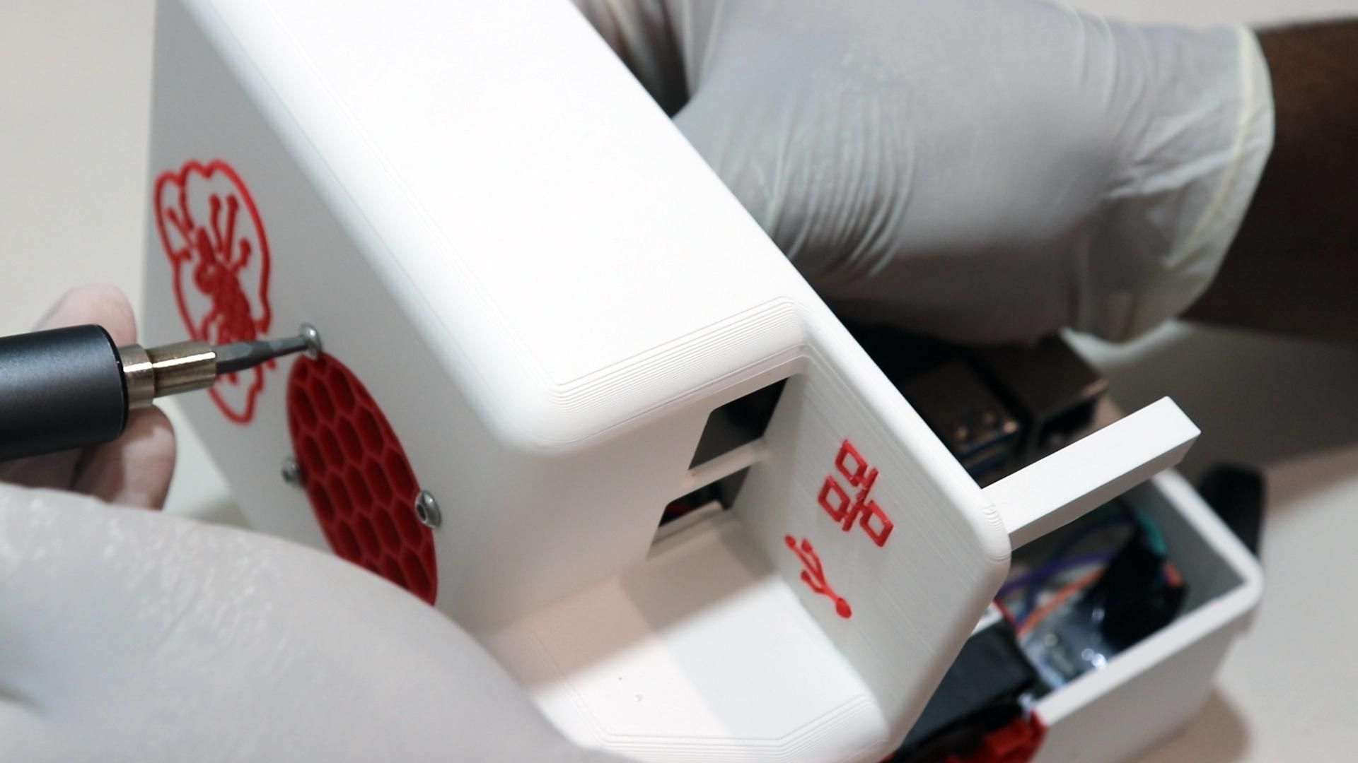
Now for the second fan, this time, you won't need any mounting kits apart from screws.
Use 4x M3x16 screws and nuts to secure the fan onto the top of the case.
Close Up the Case
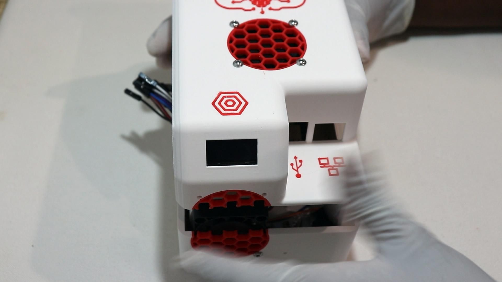
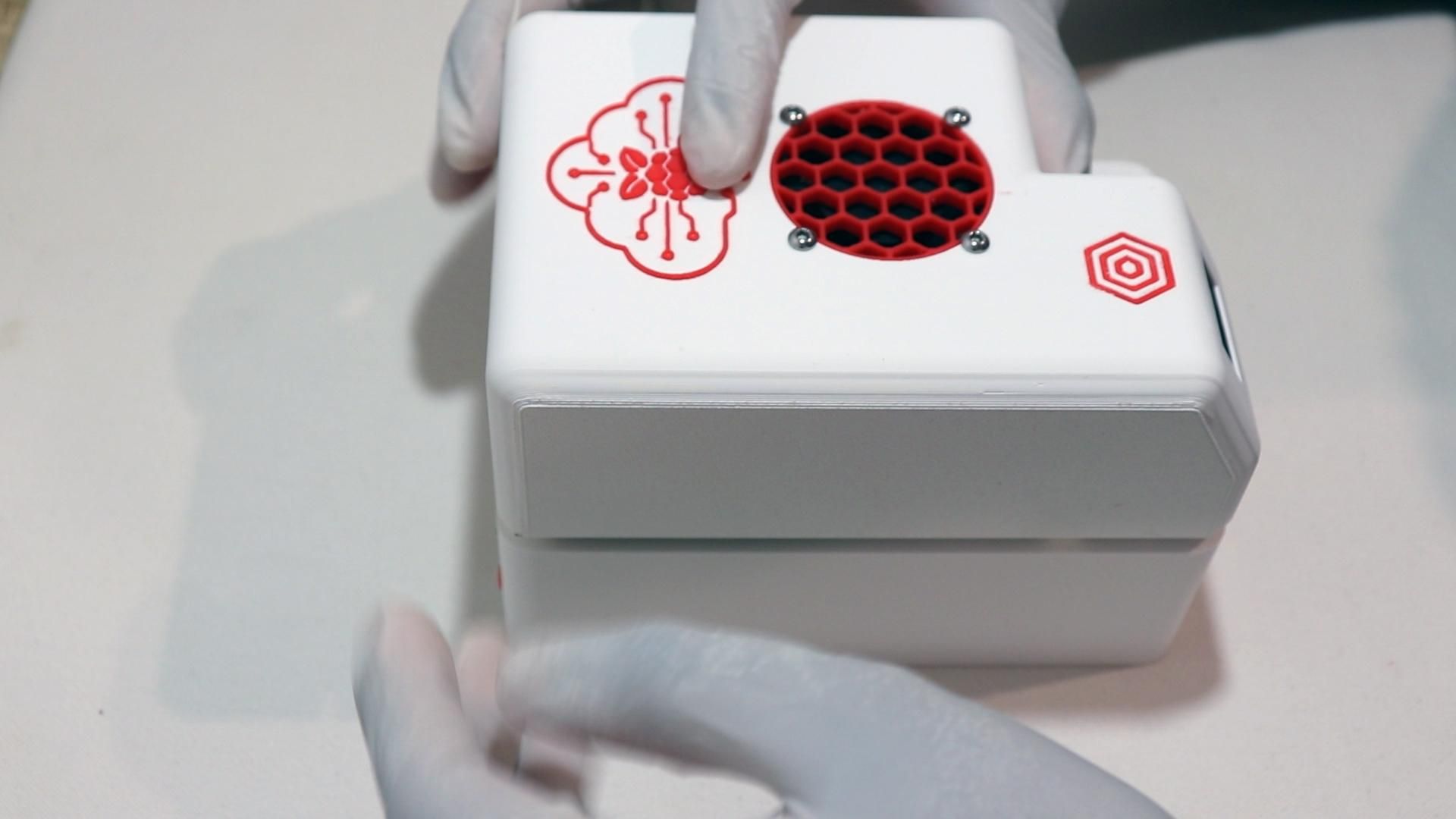
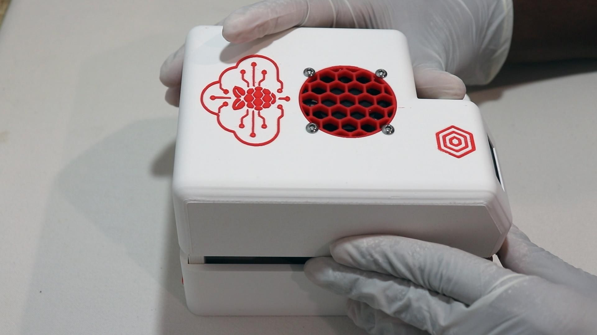
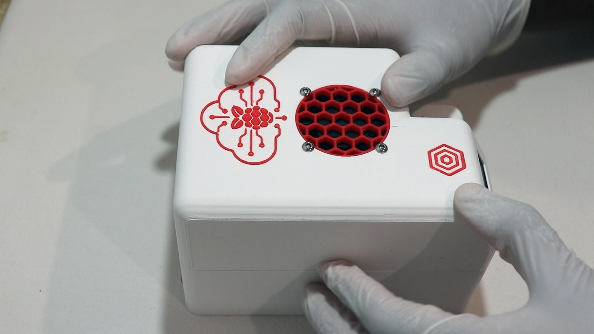
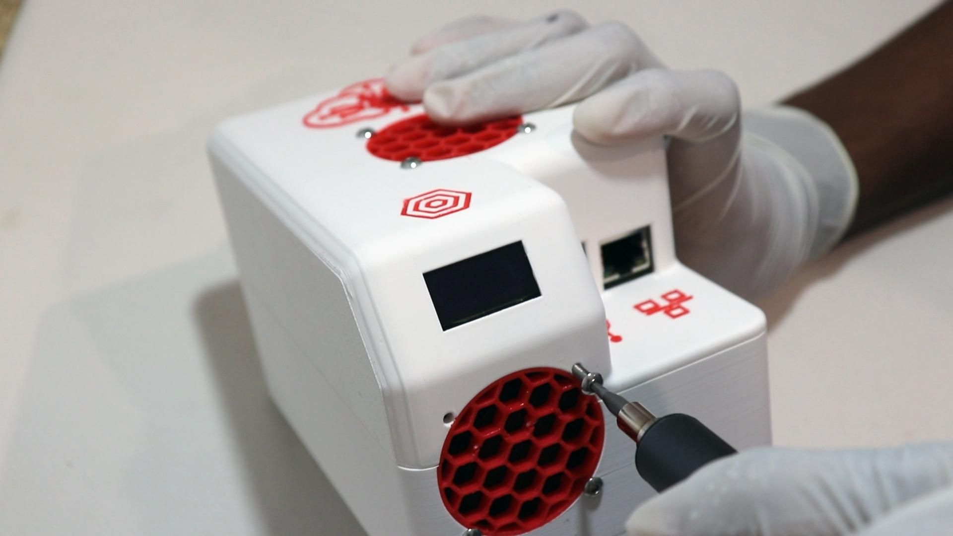
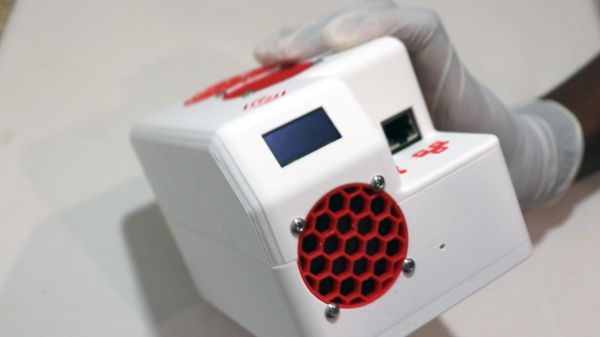
Now, carefully tuck all the wiring back inside the case.
Ensure that nothing is pinched or resting against a fan blade or battery terminal before gently pressing down on the top case to seal up the server.
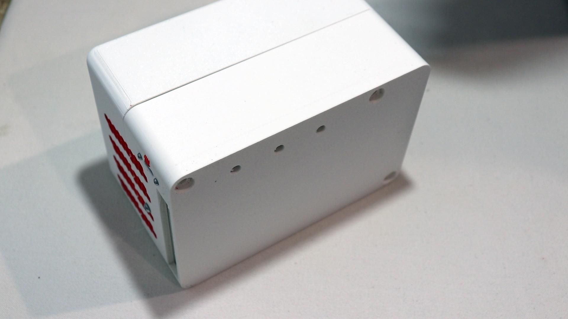
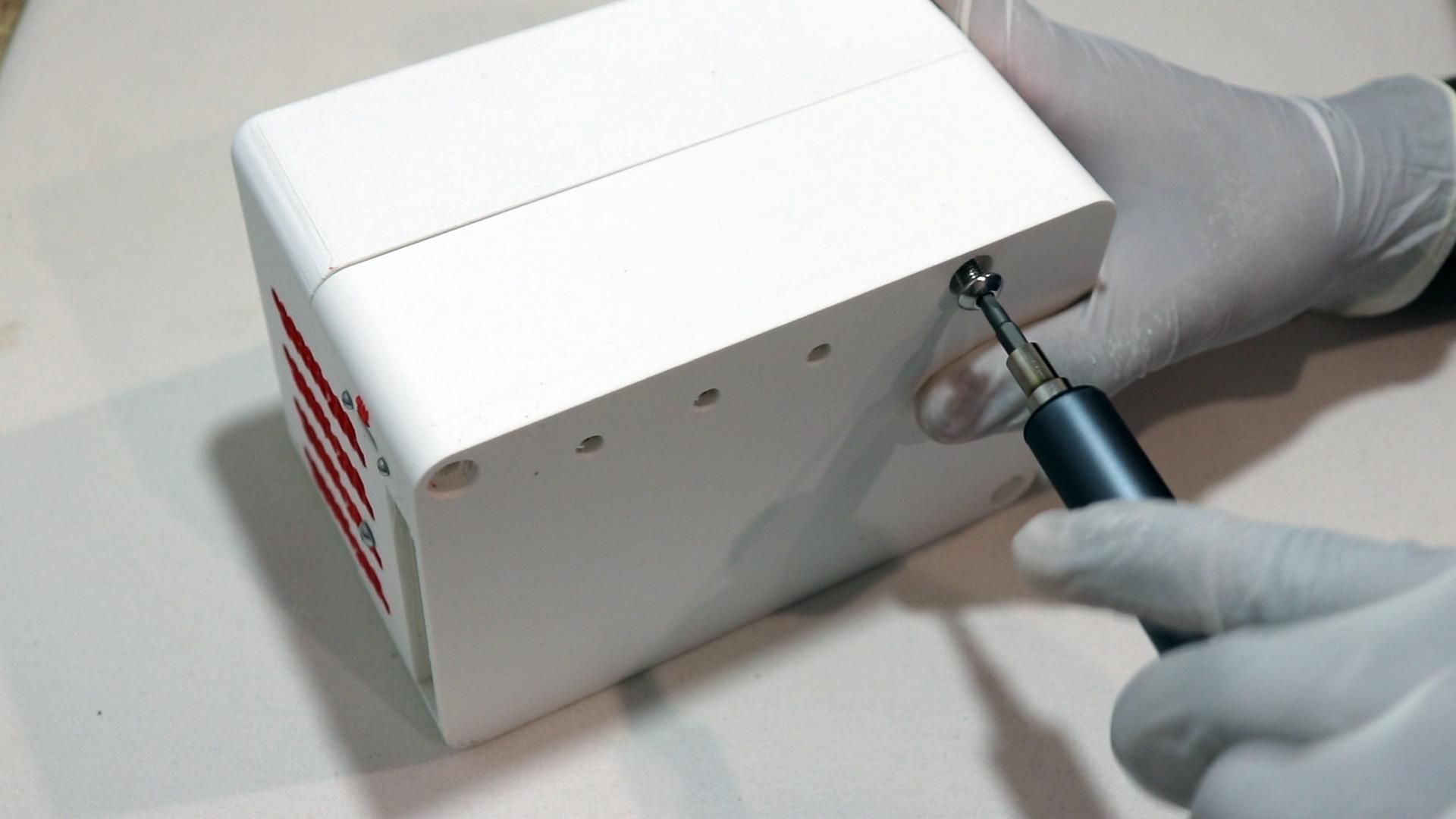
Flip the assembled case over and screw the two halves together from the bottom using 3x M5x12 screws.
Do a visual check to ensure that the server looks good before continuing.
Install the Drive Handle
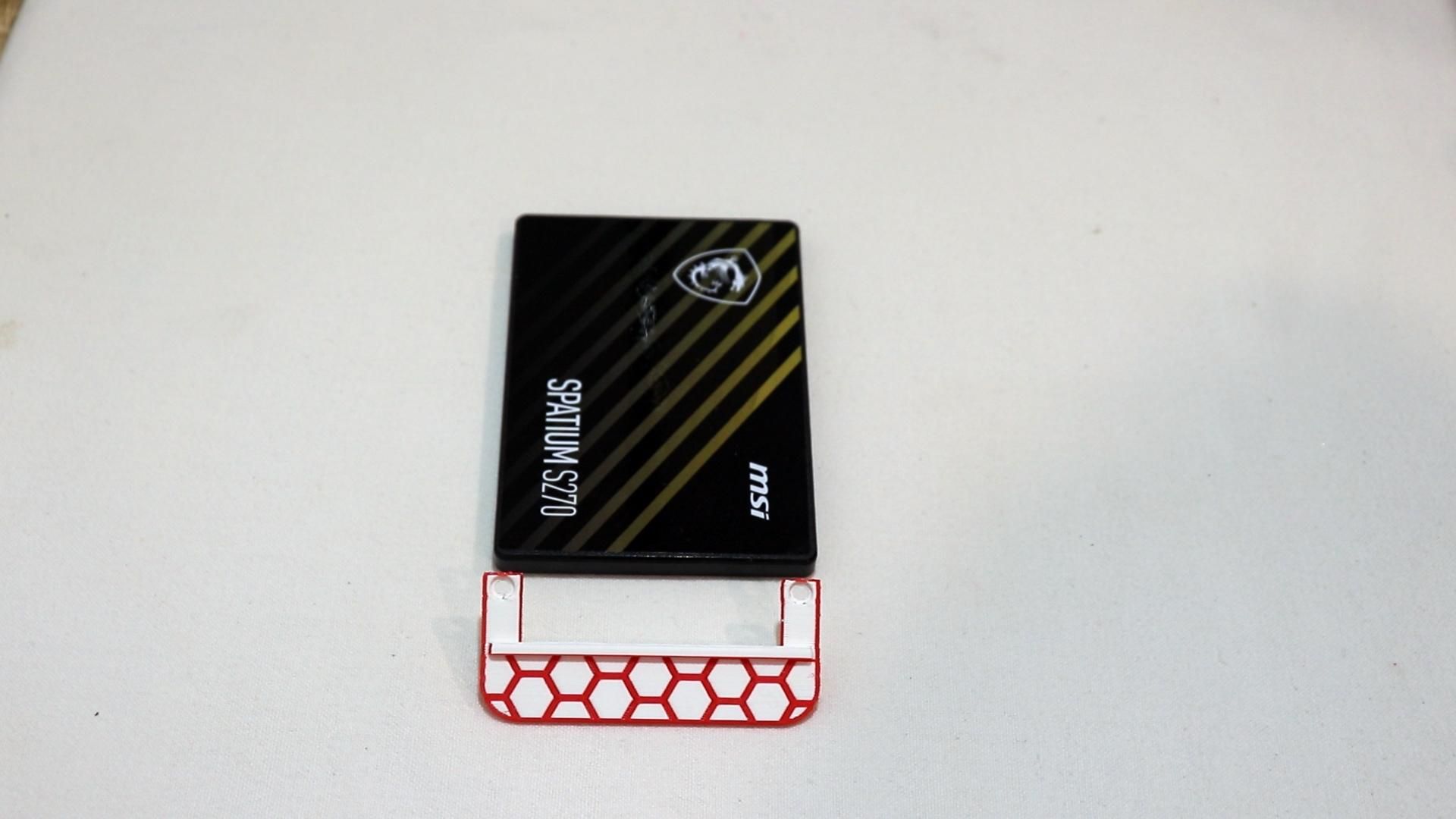
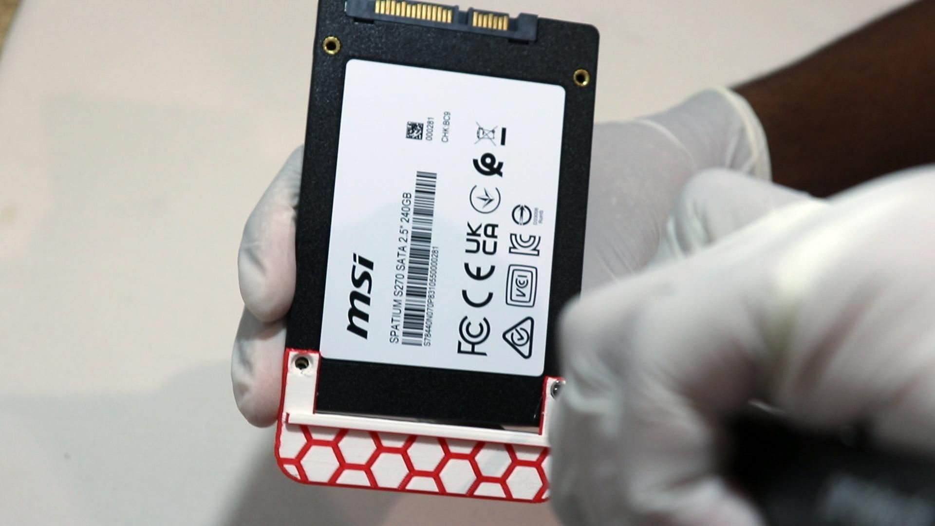
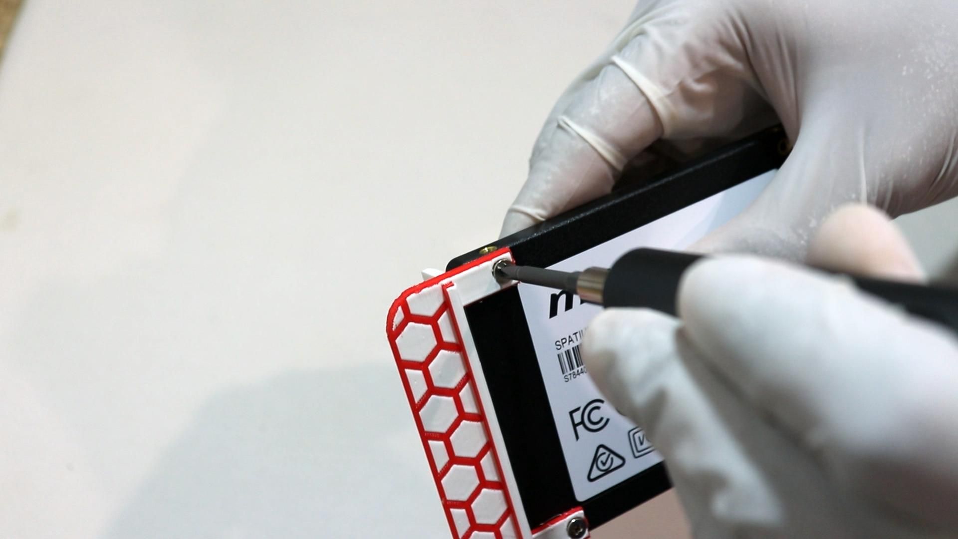
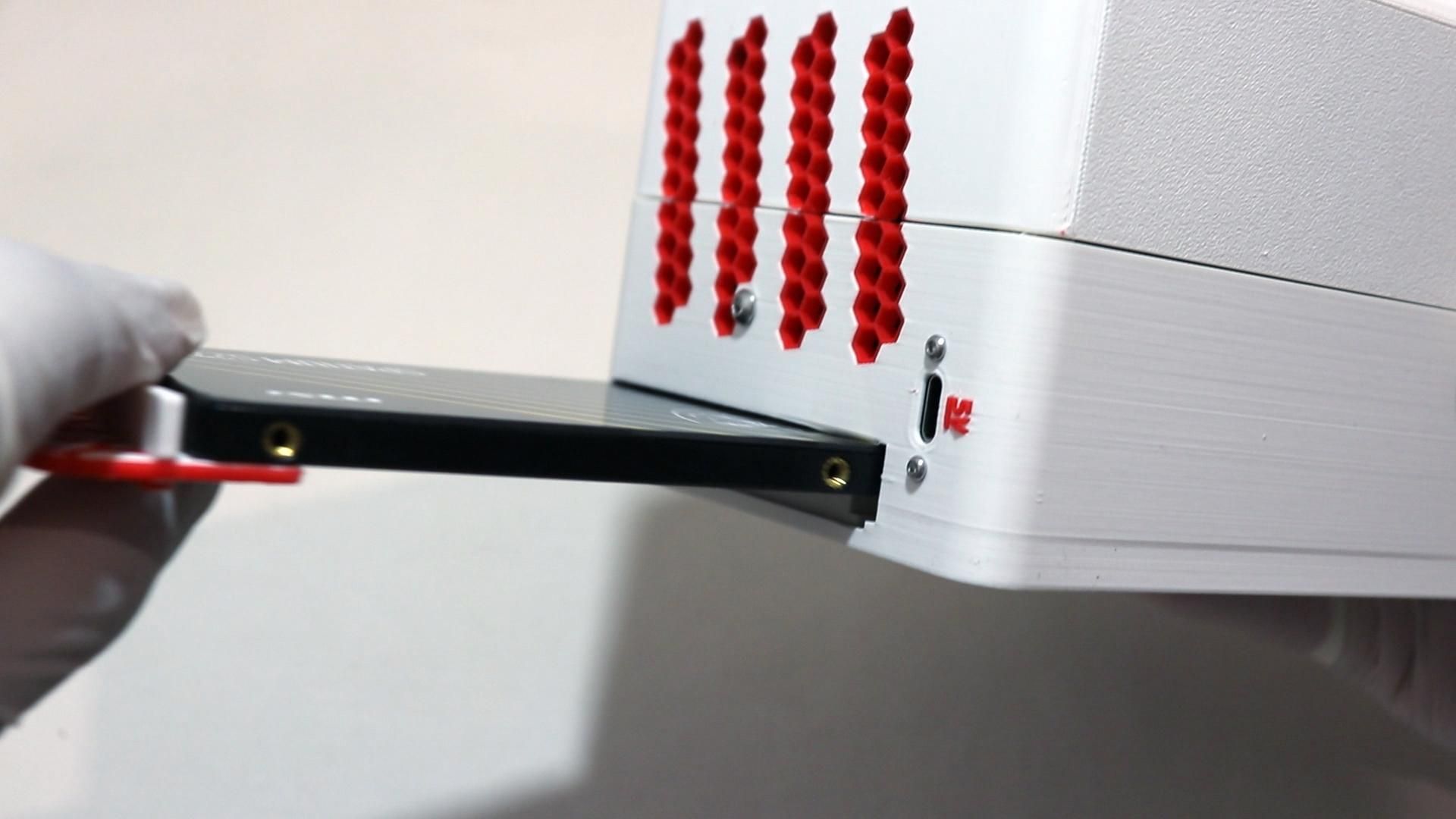
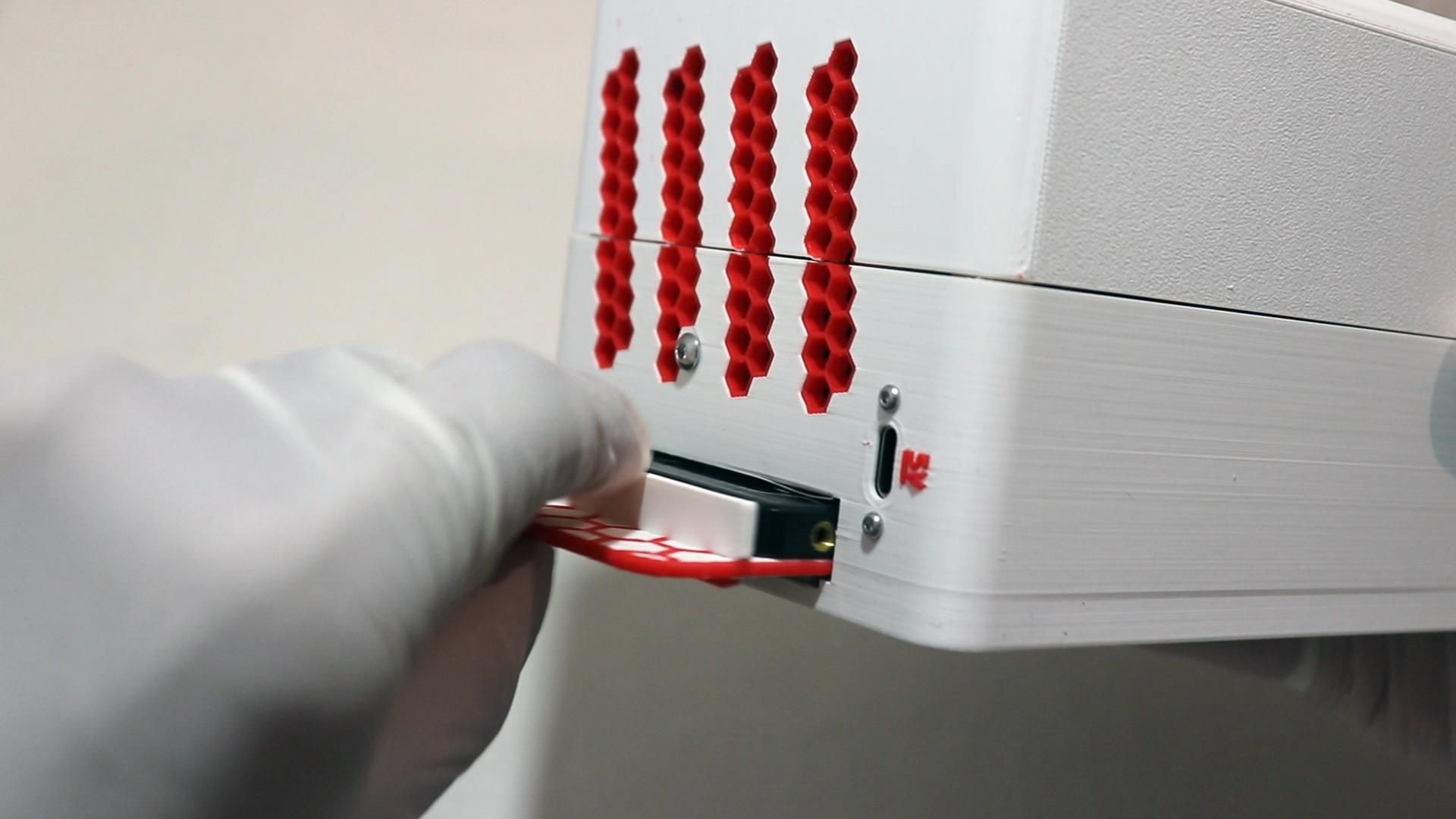
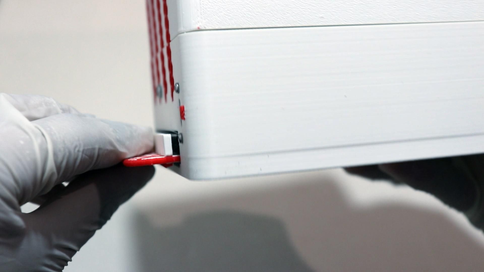
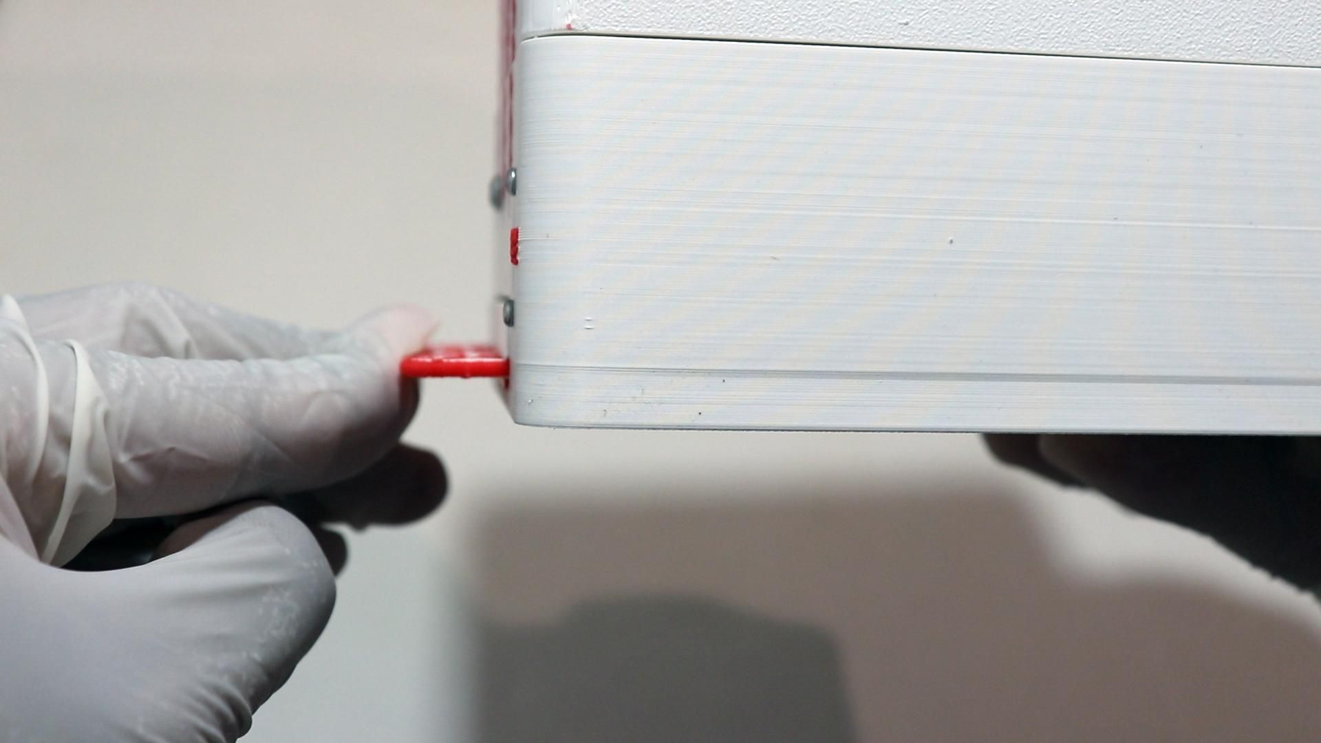
Now, to complete the hardware setup, install the printed drive handle onto your SSD!
This is what lets you actually hot swap the SSD later since the drive will be flush with the case otherwise.
- Simply line the printed handle up with the SSD's mounting holes on the bottom of the drive.
- Secure it using 2x standard SSD drive screws (they usually come with your 2.5" drive).
- Test-slide the drive in and out of the SATA-to-USB adapter slot at the bottom to confirm everything works!
Software Setup
Note: This project runs 64-bit Raspberry Pi OS (Optionally the lite version). Flash it with Raspberry Pi Imager, boot the Pi, and get it on your network before continuing.
Now it's time to set up the Pi's software.
Begin by enabling I2C (Required for the OLED)
Then go to Interface Options -> I2C ->Enable before rebooting with
Once you're back, make sure your OLED is detected with
You should see an address (likely 0x3C) show up in the grid. Write it down or make sure to remember it since you'll be needing it next!
Installing RaspiMonitor
RaspiMonitor is a small custom Python script that drives the OLED status screen, watches the touch button, and controls the LTE dongle hotspot fallback mode!
It's a simple python script so to install it, first download the code via
Then create a virtual environment in Python within the folder using
Now activate the virtual environment
before installing the required dependencies with
Once thats done, open the config.json file and ensure all settings are correct
If you used a different LTE dongle than the Huawei one I used in this build, check the dongle profile/config section of the main monitor.py script and update the device identifiers to match your model.
Once you've confirmed that your OLED's address (found in the previous step), pin locations and other information are correct, launch the script as root with:
Root (sudo) is required in order to allow the program access to the GPIO pins on the Raspberry Pi.
Once you have verified that everything is working, press CTRL + C to exit the program. Since it's unrealistic to start the script manually on every boot, we'll make it a startup script.
To make the script start on launch, type
The nano text editor will launch, and within it, you can paste the following configuration inside. Ensure you edit the "<your username here!>" with your actual username (most likely pi if you kept it as default during your install)
Once you save and exit the file, run the following commands to start it up and enable it!
Conclusion
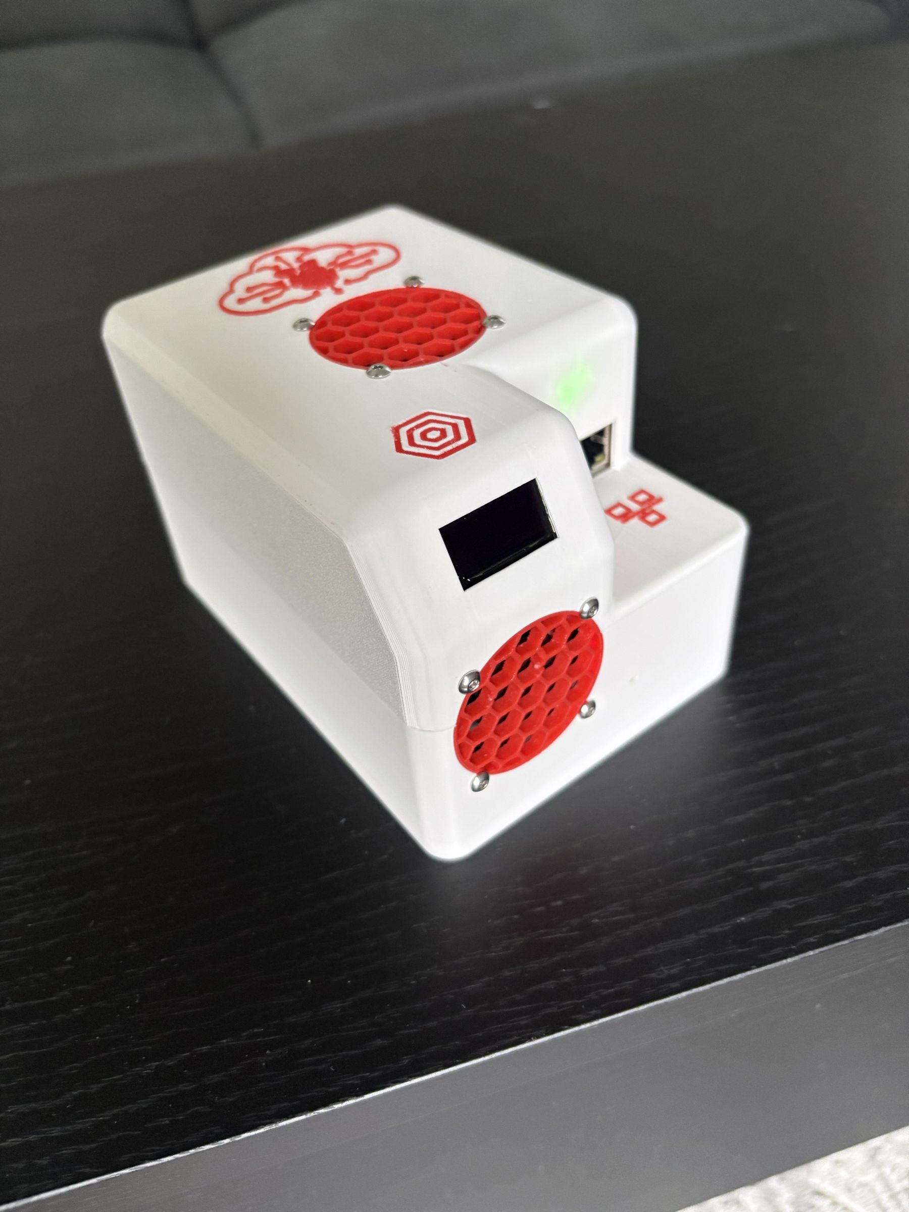
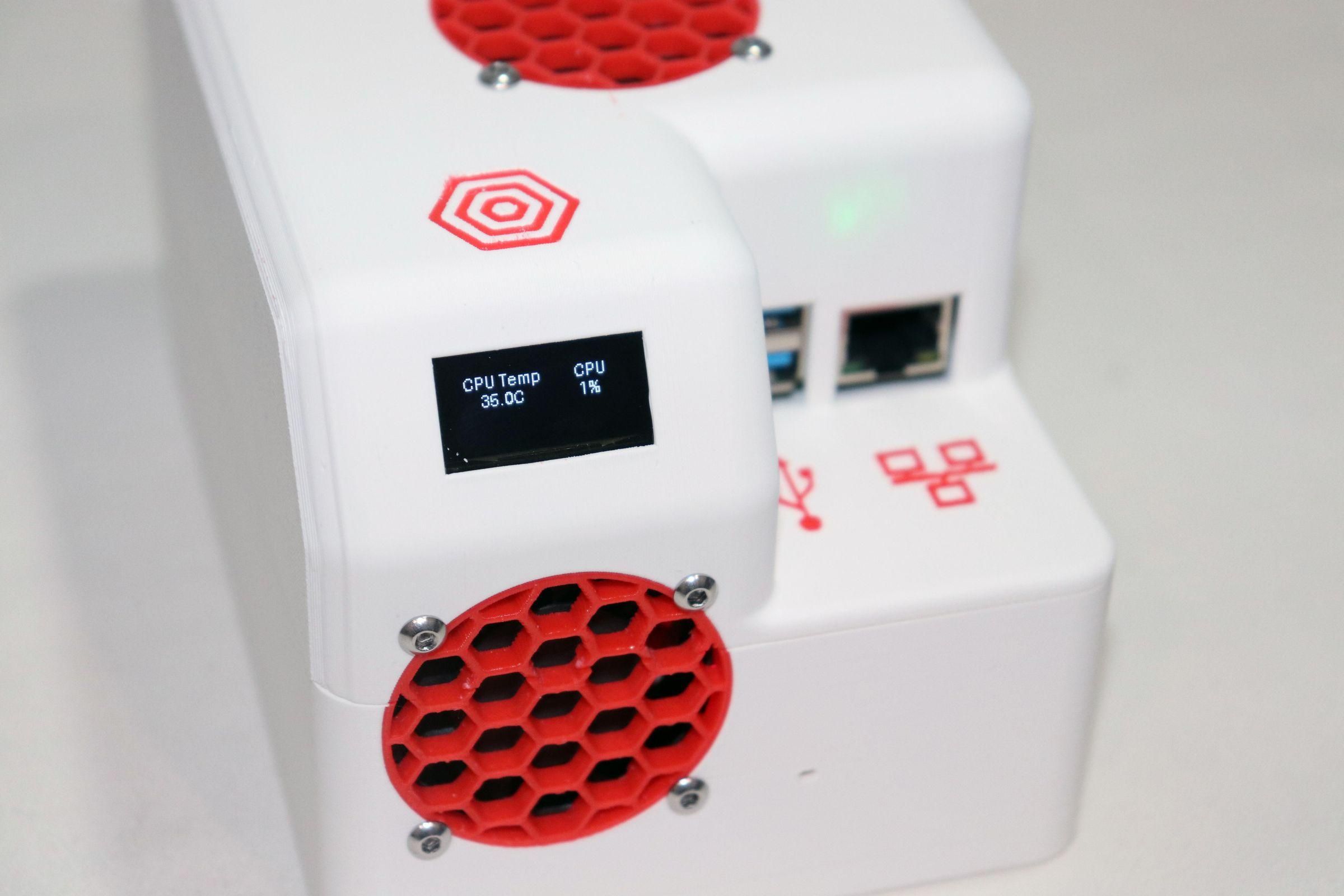
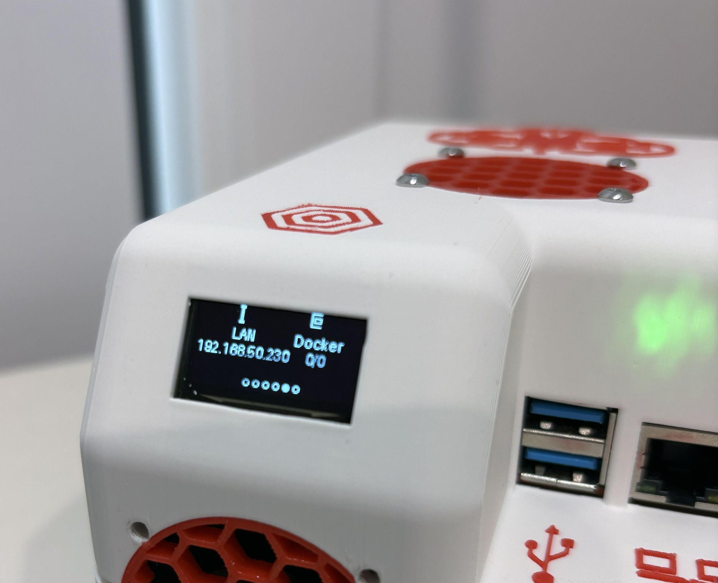
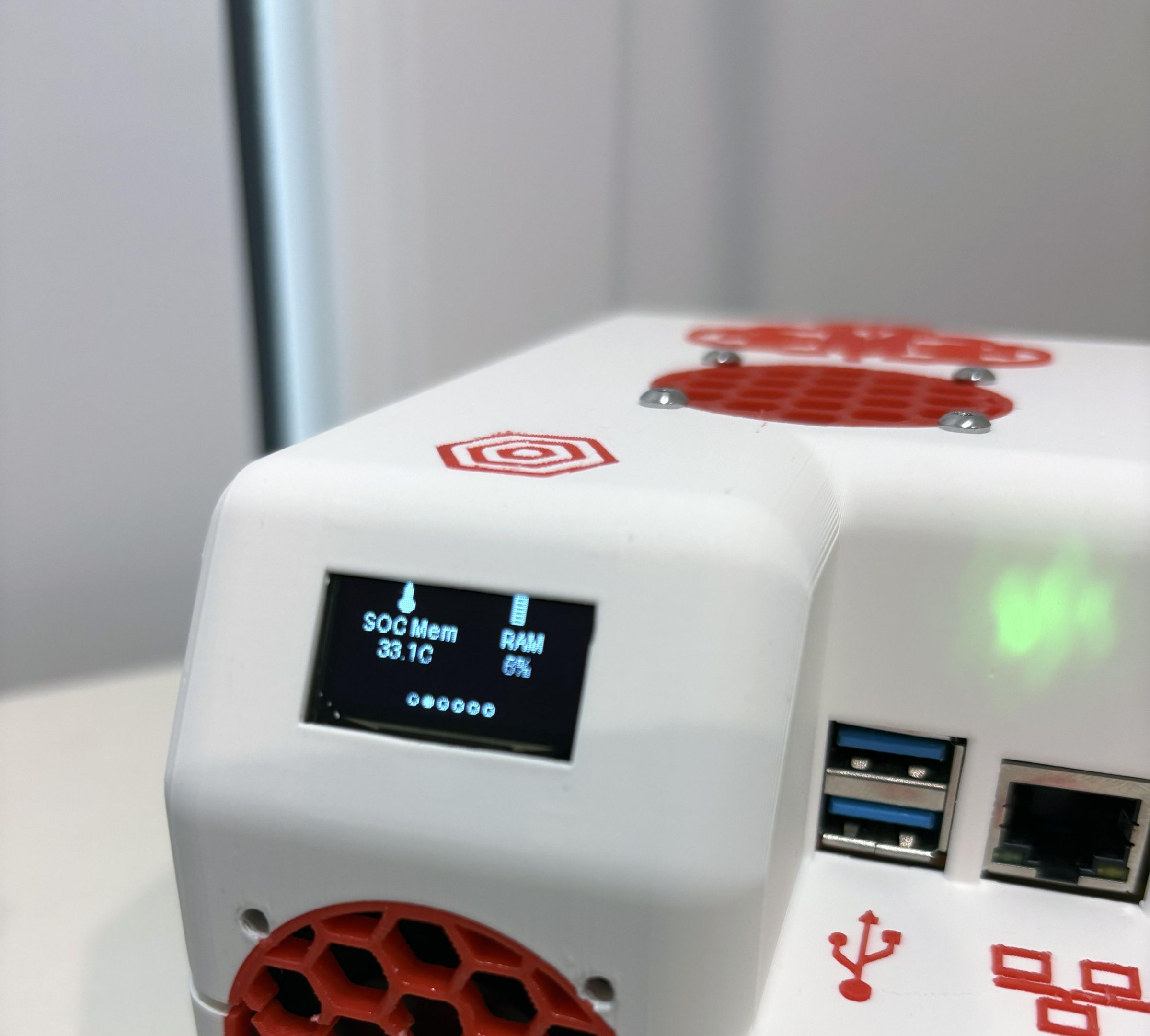
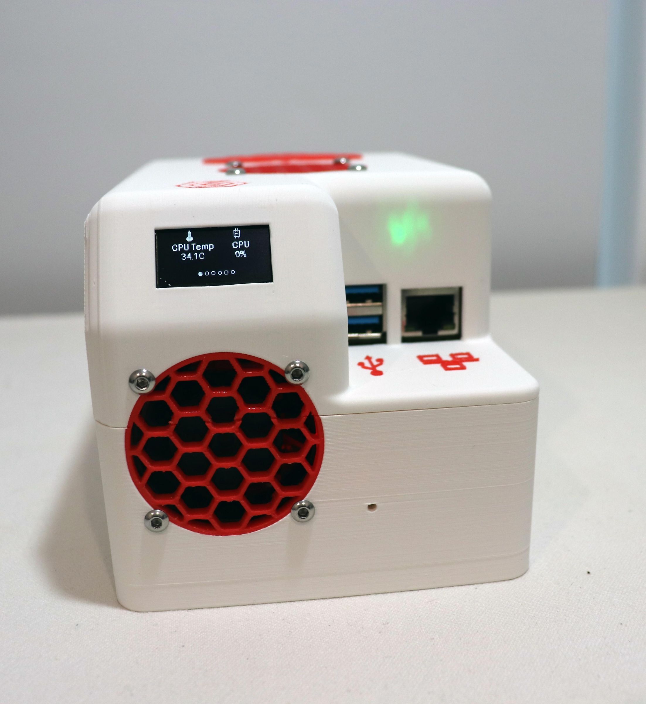
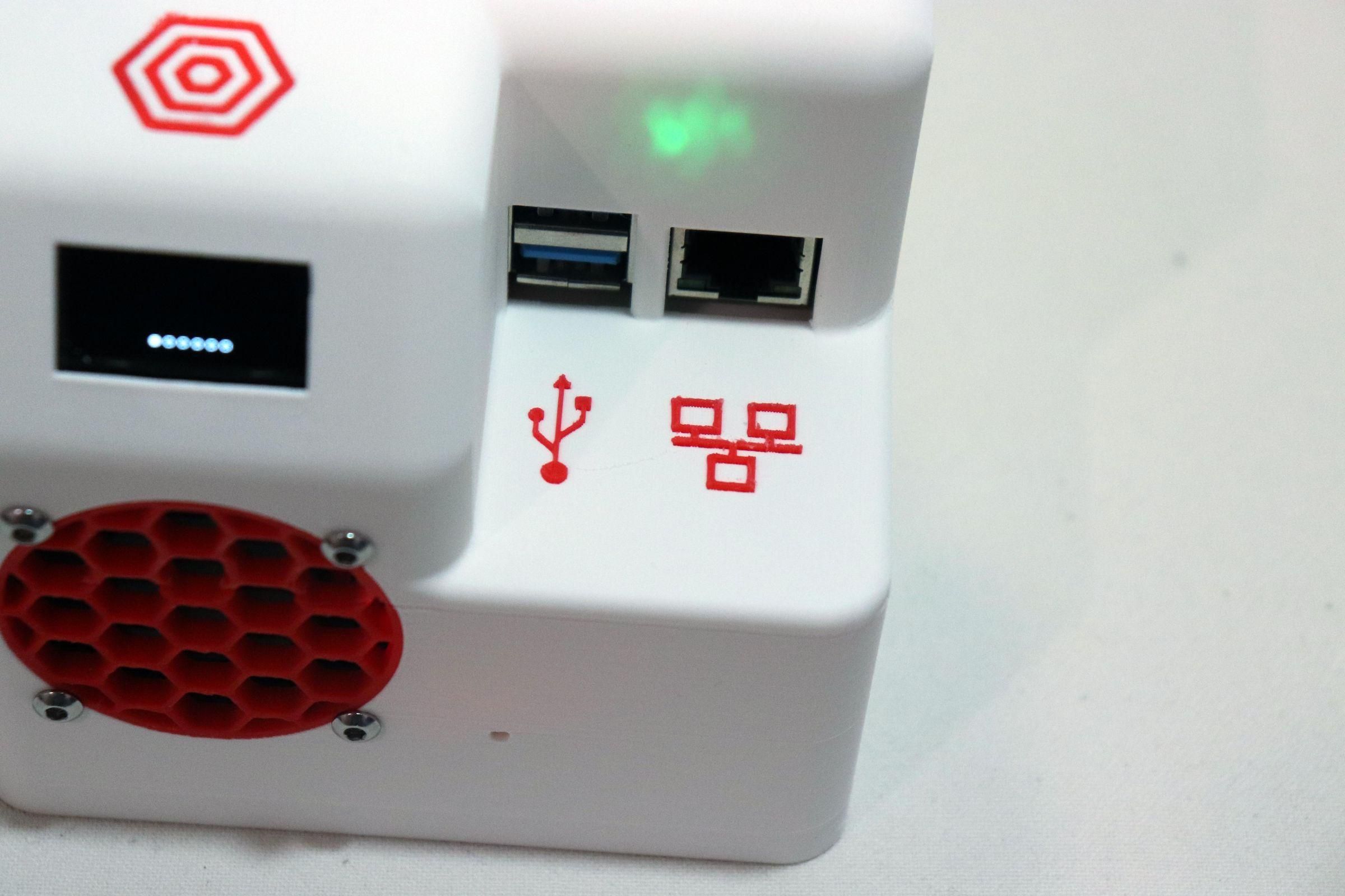
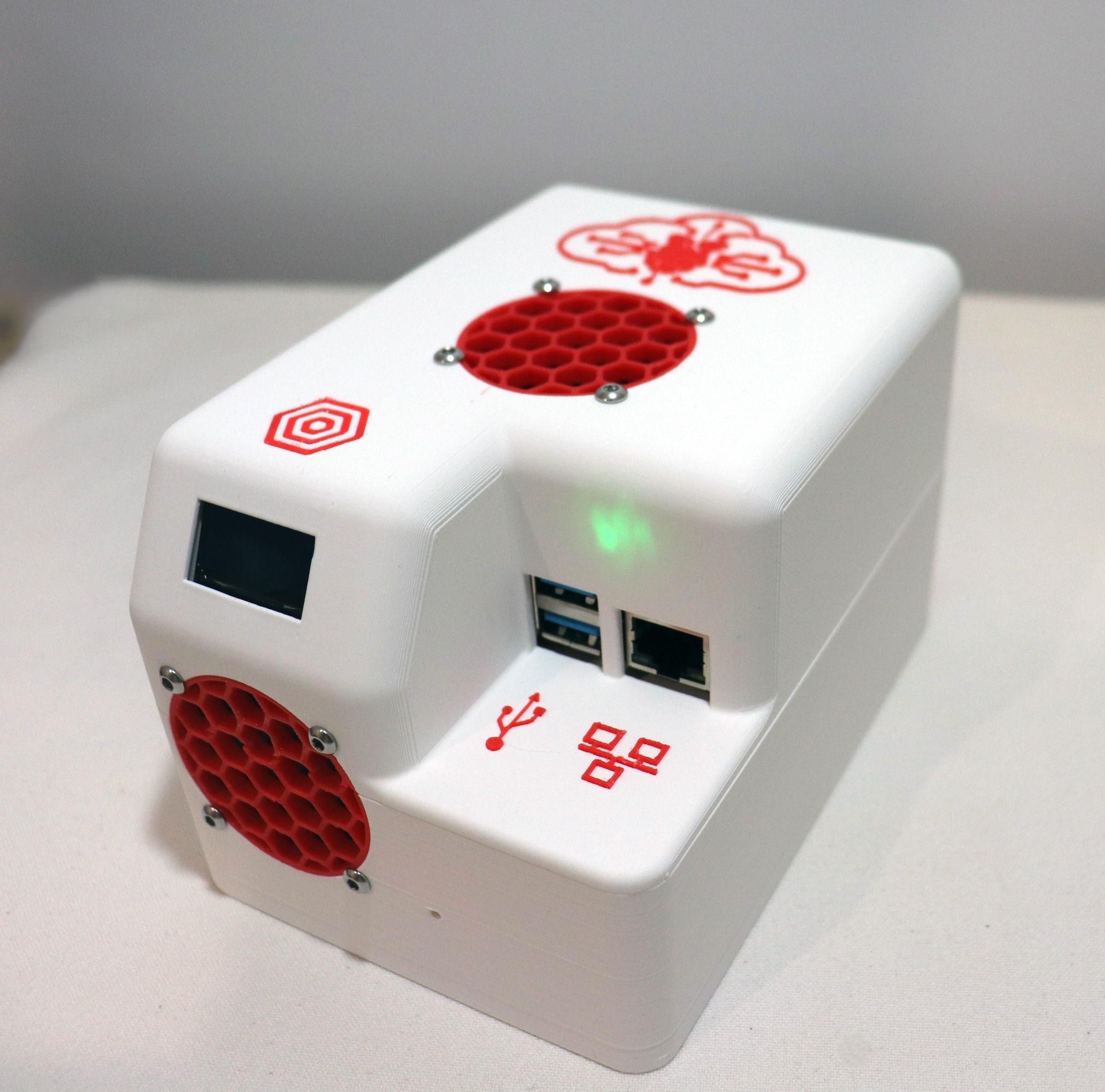
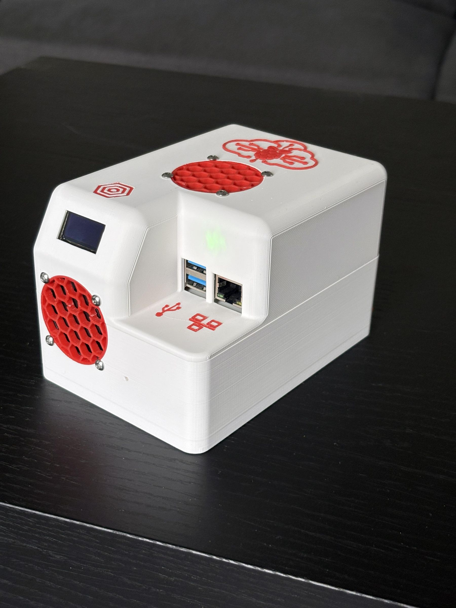
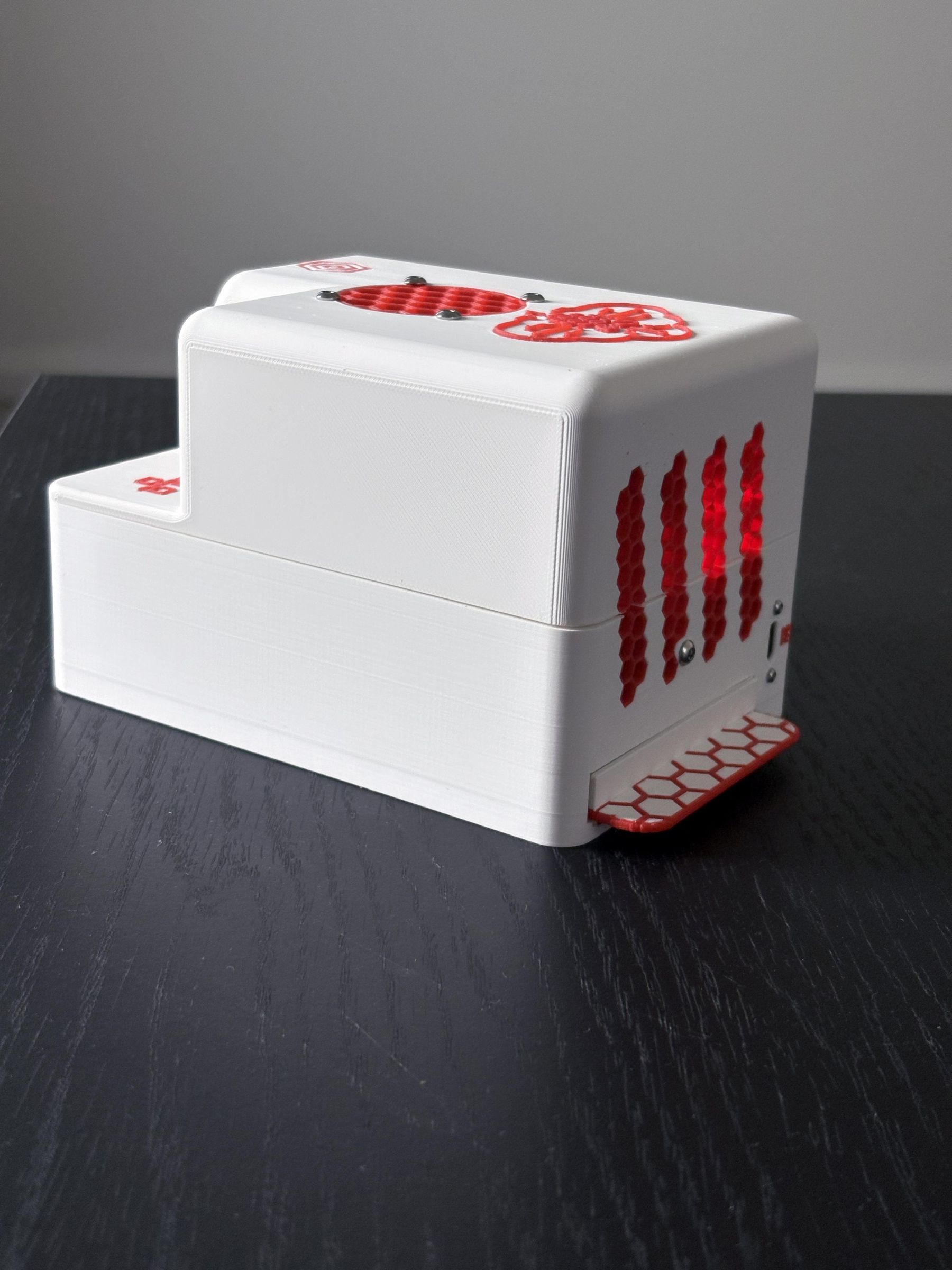
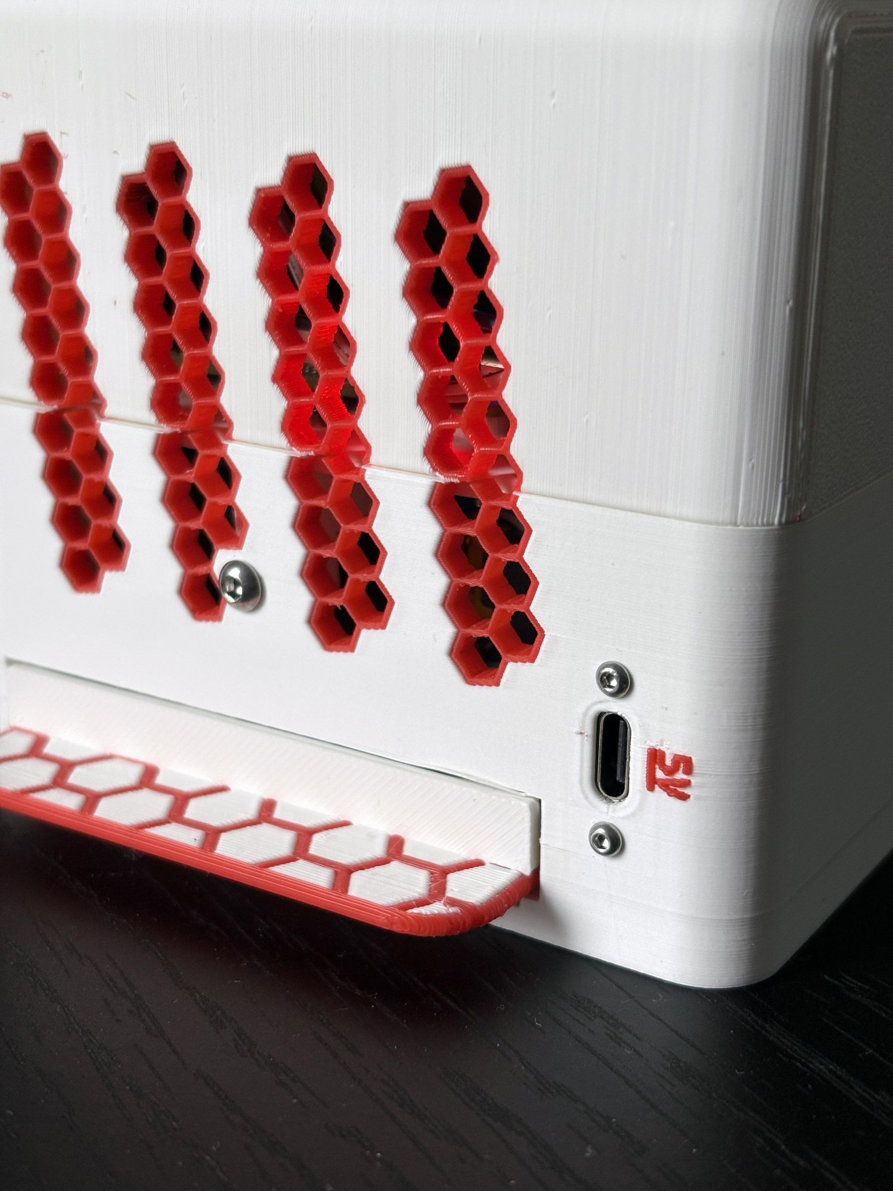
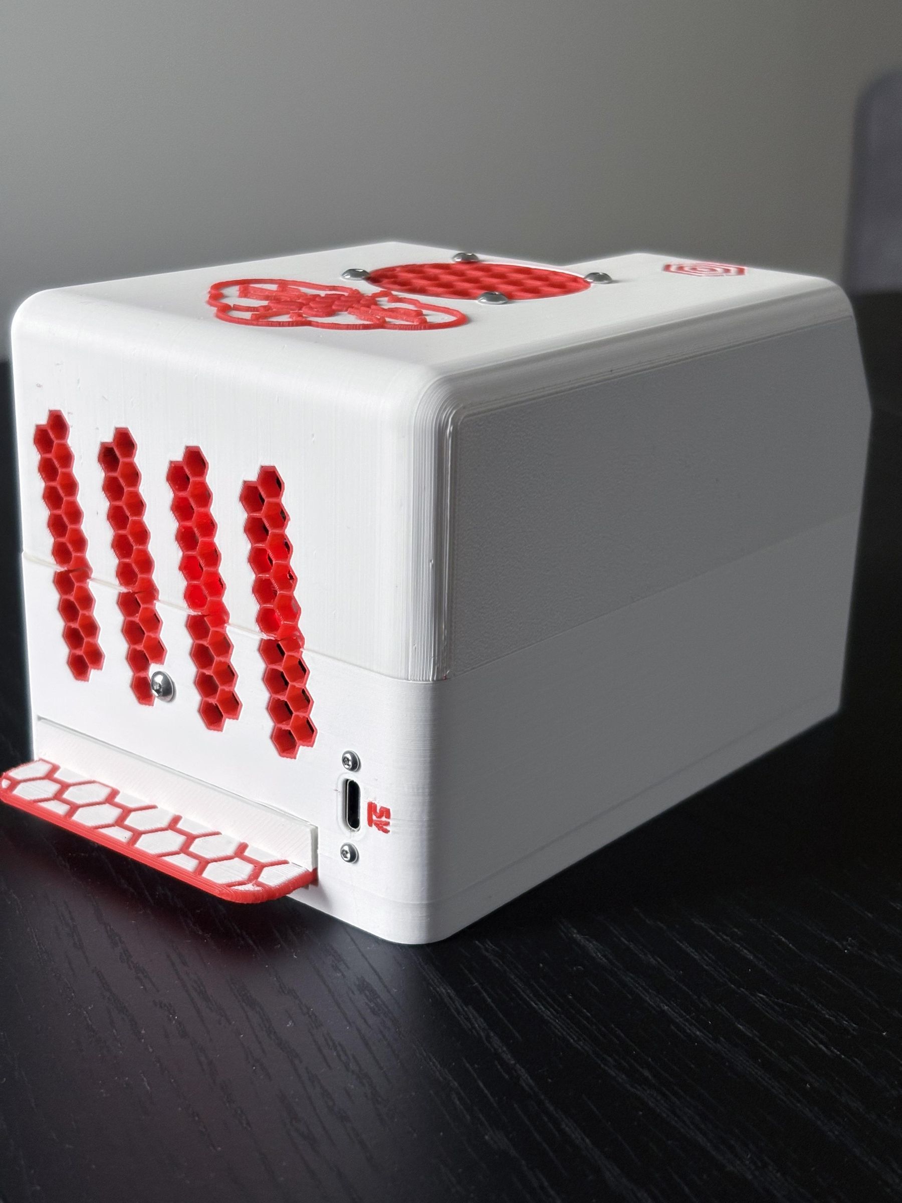
Finally, after all that work, what you end up with is a perfectly sized, self-contained, fully independent Lifepod server!
Just plug the Lifepod into the wall using a 5V adapter, and if the power drops... nothing happens! The UPS module instantly switches to the beefy 18650 battery pack below, and the Raspberry Pi doesn't even notice it for hours.
If you build this, I would strongly recommend populating all 3 battery slots with maximum-capacity batteries for the most enjoyable experience. Mechanically and electrically, the system is ready for a third cell, which means it's a no-brainer!
Also, feel free to swap in a better UPS/BMS module than the MHCD42 I used. Honestly, mine was quite a bit finicky, and I wouldn't recommend it for future builds.
You could use a different LTE dongle, or even a bigger SSD, or even a 2.5" HDD, provided you meet the power requirements.
If you build your own version, I'd love to see it. Good luck and enjoy your fully outage-proof server!