Line Follower Car
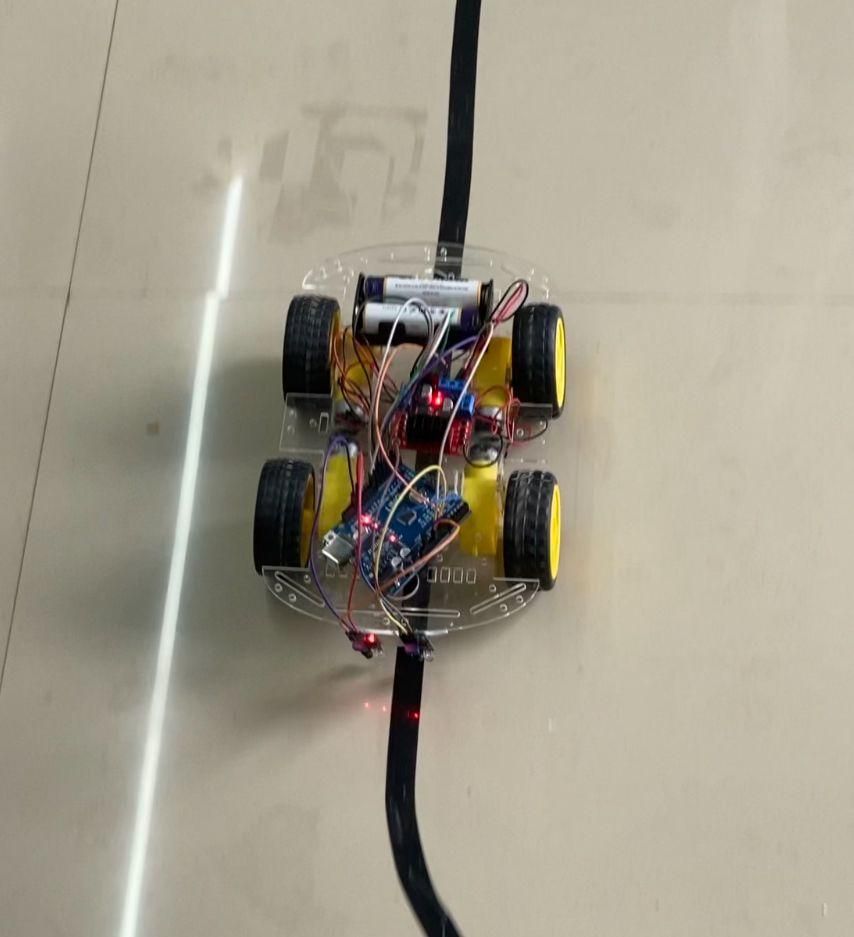
Have you ever wondered how autonomous robots can follow a predefined path without human intervention? In this project, I will show you how to build a simple Arduino-based Line Following Car using two IR sensors and an L298N motor driver. The robot detects a black line on a white surface and automatically steers itself to stay on the track.
This project is perfect for beginners who want to learn the basics of robotics, sensor interfacing, and motor control. It is inexpensive, easy to assemble, and can be upgraded with more advanced features such as PID control and obstacle avoidance.
Supplies
1 × Arduino Uno
2 × IR Sensor Modules
1 × L298N Motor Driver Module
2 × BO DC Geared Motors
2 × Robot Wheels
1 × Robot Chassis
1 × 7.4V Li-ion Battery Pack (or 9V Battery)
1 × Battery Holder
Jumper Wires
USB Cable for Arduino
Breadboard (Optional)
Nuts and Bolts for mounting
How It Works
The robot uses two IR sensors mounted underneath the front of the chassis. Each sensor emits infrared light and measures the reflected light from the surface below.
- White surfaces reflect more infrared light.
- Black surfaces absorb infrared light.
The Arduino continuously reads the outputs from both sensors and controls the motors based on which sensor detects the black line.
Robot behavior:
- Both sensors detect the white surface → Move Forward
- Left sensor detects the black line → Turn Left
- Right sensor detects the black line → Turn Right
- Both sensors detect the black line → Stop (or move forward depending on your program)
Circuit Connections
Connect the Left IR Sensor
- VCC → Arduino 5V
- GND → Arduino GND
- OUT → Arduino Digital Pin 2
Connect the Right IR Sensor
- VCC → Arduino 5V
- GND → Arduino GND
- OUT → Arduino Digital Pin 3
Connect the L298N Motor Driver
- IN1 → Arduino Pin 8
- IN2 → Arduino Pin 7
- IN3 → Arduino Pin 4
- IN4 → Arduino Pin 5
- ENA → Arduino Pin 9
- ENB → Arduino Pin 10
- GND → Arduino GND
Power Connections
- Battery Positive → L298N +12V Terminal
- Battery Negative → L298N GND
Motor Connections
- Left Motor → OUT1 and OUT2
- Right Motor → OUT3 and OUT4
Assemble the Robot
Attach both DC motors to the robot chassis.
Install the wheels onto the motor shafts.
Fix the caster wheel to the front or rear of the chassis.
Mount the Arduino Uno securely.
Fix the L298N motor driver onto the chassis.
Position the two IR sensors underneath the front of the robot.
Keep the sensors approximately 5–8 mm above the ground.
Complete all wiring and check every connection before powering the robot.
Upload the Arduino Code
// Motor Pins
#define ENA 9
#define IN1 8
#define IN2 7
#define ENB 10
#define IN3 4
#define IN4 5
// IR Sensors
#define LEFT_SENSOR 2
#define RIGHT_SENSOR 3
void setup() {
pinMode(LEFT_SENSOR, INPUT);
pinMode(RIGHT_SENSOR, INPUT);
pinMode(ENA, OUTPUT);
pinMode(IN1, OUTPUT);
pinMode(IN2, OUTPUT);
pinMode(ENB, OUTPUT);
pinMode(IN3, OUTPUT);
pinMode(IN4, OUTPUT);
analogWrite(ENA, 180);
analogWrite(ENB, 180);
}
void loop() {
int left = digitalRead(LEFT_SENSOR);
int right = digitalRead(RIGHT_SENSOR);
if(left == LOW && right == LOW)
{
forward();
}
else if(left == HIGH && right == LOW)
{
leftTurn();
}
else if(left == LOW && right == HIGH)
{
rightTurn();
}
else
{
stopRobot();
}
}
void forward()
{
digitalWrite(IN1,HIGH);
digitalWrite(IN2,LOW);
digitalWrite(IN3,HIGH);
digitalWrite(IN4,LOW);
}
void leftTurn()
{
digitalWrite(IN1,LOW);
digitalWrite(IN2,LOW);
digitalWrite(IN3,HIGH);
digitalWrite(IN4,LOW);
}
void rightTurn()
{
digitalWrite(IN1,HIGH);
digitalWrite(IN2,LOW);
digitalWrite(IN3,LOW);
digitalWrite(IN4,LOW);
}
void stopRobot()
{
digitalWrite(IN1,LOW);
digitalWrite(IN2,LOW);
digitalWrite(IN3,LOW);
digitalWrite(IN4,LOW);
}
Testing
Connect the Arduino to your computer and upload the program.
Place the robot on a white surface with a black electrical tape line.
Turn on the battery power.
Adjust the sensitivity of both IR sensors using the onboard potentiometers.
Observe the robot following the line and fine-tune the sensor position if necessary.
Troubleshooting
Robot moves in the wrong direction
Swap the wires of the motor that is rotating in the wrong direction.
Robot cannot detect the line
- Adjust the IR sensor sensitivity.
- Reduce the height of the sensors.
- Ensure the track has good contrast.
- Check all wiring connections.
Robot keeps turning
- Verify that both sensors are working correctly.
- Check the Arduino pin assignments.
- Inspect the sensor alignment.
Motors do not run
- Check the battery voltage.
- Ensure the motor driver is powered.
- Verify the wiring between the Arduino and the motor driver.
Future Improvements
You can improve this project by adding:
- PID control for smoother movement
- Five or eight IR sensors for higher accuracy
- OLED display
- Bluetooth or Wi-Fi control
- Obstacle avoidance using an ultrasonic sensor
- Adjustable motor speed using PWM
- Rechargeable battery charging circuit
- 3D-printed chassis
- Maze-solving capability