Line Follower Using Arduino
Introduction
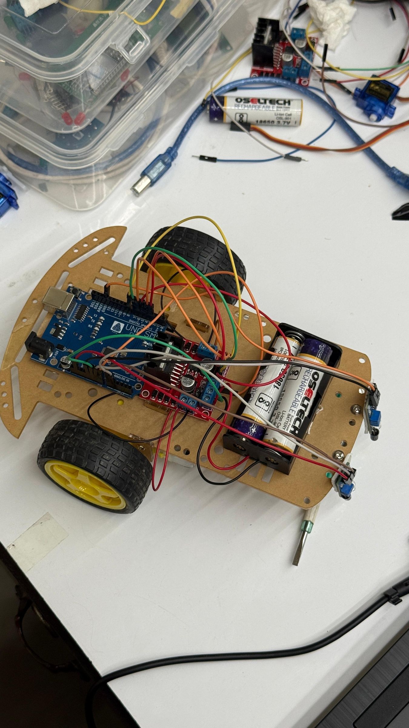
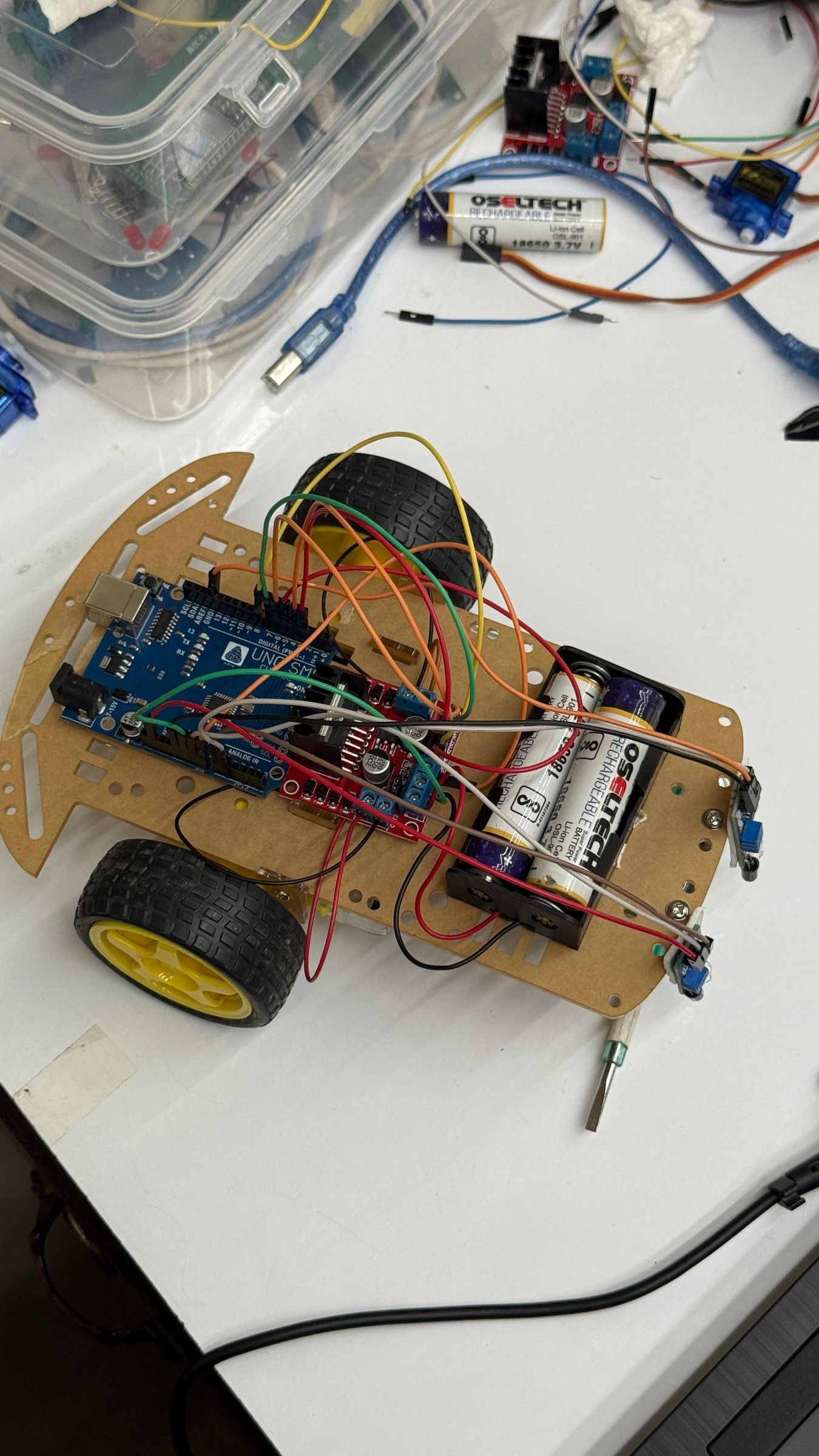
A line follower robot is one of the most popular beginner robotics projects because it introduces the fundamentals of embedded systems, sensor interfacing, and motor control. This robot is designed to automatically detect and follow a predefined black line on a lighter surface without requiring manual control.
In this project, we built a simple and cost-effective line follower robot using an Arduino Uno, two infrared (IR) sensors, and an L298N motor driver. The IR sensors continuously detect the position of the black line, while the Arduino processes the sensor data and controls the DC motors to keep the robot moving along the desired path.
This project is ideal for students, hobbyists, and beginners who want to gain practical experience with Arduino programming, robotics, and automation. It demonstrates how sensors and microcontrollers work together to create an autonomous system capable of making real-time navigation decisions.
By following this guide, you will learn how to assemble the robot, connect the electronic components, upload the Arduino code, and test the robot on a custom-made track. Once completed, this project can be further enhanced with additional sensors, PID control algorithms, or wireless communication for more advanced robotics applications.
Supplies
Supplies
- Arduino Uno
- L298N Motor Driver Module
- 2 × IR Sensor Modules (Line Tracking Sensors)
- 2 × DC Gear Motors
- Robot Chassis
- 2 × Robot Wheels
- 1 × Caster Wheel
- 7.4V Li-ion Battery Pack (or 9V–12V battery source)
- Battery Holder
- Jumper Wires (Male-to-Male and Male-to-Female)
- USB Cable (for programming the Arduino)
- Mounting Hardware (screws, nuts, spacers, or double-sided tape)
- Small Screwdriver (for adjusting the IR sensor potentiometers)
- Black Electrical Tape or Printed Black Line Track (for testing)
Complete Steps
Arduino Line Follower Robot Using IR Sensors
Step 1: Introduction
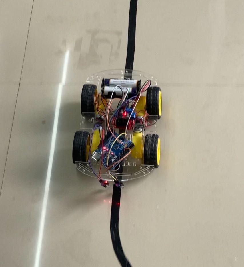
A line follower robot is an autonomous robot that follows a predefined path marked by a black line on a light-colored surface. It uses infrared (IR) sensors to detect the position of the line and an Arduino Uno to control the movement of the motors. This project is an excellent introduction to robotics, sensor interfacing, and embedded systems, making it suitable for beginners, students, and hobbyists.
Step 2: Supplies
- Arduino Uno
- L298N Motor Driver Module
- 2 × IR Sensor Modules
- 2 × DC Gear Motors
- Robot Chassis
- 2 × Wheels
- 1 × Caster Wheel
- 7.4V Battery Pack (or suitable power source)
- Battery Holder
- Jumper Wires
- USB Cable
- Double-sided Tape or Mounting Screws
- Black Electrical Tape (to create the track)
Step 3: Assemble the Chassis
Fix both DC gear motors to the robot chassis and attach the wheels. Install the caster wheel to provide balance. Ensure all components are tightly secured before proceeding.
Step 4: Mount the Arduino and Motor Driver
Place the Arduino Uno and the L298N motor driver on the chassis. Secure them using screws, spacers, or double-sided tape. Keep enough space for wiring and battery placement.
Step 5: Mount the IR Sensors
Attach the two IR sensors to the front of the robot.
- Keep the sensors approximately 1–2 cm above the ground.
- Position them side by side so they can accurately detect the black line.
- Make sure both sensors are aligned properly.
Step 6: Wiring Connections
L298N to Arduino
- ENA → D5
- ENB → D6
- IN1 → D2
- IN2 → D3
- IN3 → D4
- IN4 → D7
IR Sensors
- Left IR OUT → D9
- Right IR OUT → D10
- Both VCC → 5V
- Both GND → GND
Power Supply
- Battery Positive → L298N VIN (12V terminal)
- Battery Negative → L298N GND
- Connect Arduino GND and L298N GND together.
Step 7: Upload the Arduino Code
Open the Arduino IDE.
- Select Arduino Uno from the Board menu.
- Select the correct COM port.
- Upload the line follower code to the Arduino.
After the upload is complete, disconnect the USB cable and power the robot using the battery pack.
Step 8: Calibrate the IR Sensors
Each IR sensor has a small adjustable potentiometer.
Rotate the potentiometer until:
- The sensor correctly detects the black line.
- The indicator LED changes state when moving between the black line and the white surface.
Repeat the adjustment for both sensors.
Step 9: Test the Robot
Create a simple track using black electrical tape on a white surface.
Place the robot on the track and switch on the power.
The robot should:
- Move forward when both sensors detect the line.
- Turn left when the right sensor leaves the line.
- Turn right when the left sensor leaves the line.
- Stop if both sensors lose the line.
Step 10: Troubleshooting
Robot does not move
- Check the battery voltage.
- Verify the motor connections.
- Ensure all grounds are connected together.
Robot follows the white surface
Reverse the sensor logic in the Arduino code by swapping HIGH and LOW conditions.
Robot moves too fast
Reduce the motor speed by changing:
You can decrease the value further for slower movement.
Sensors fail to detect the line
- Readjust the IR sensor potentiometers.
- Lower the sensors closer to the ground.
- Ensure the lighting conditions are not too bright.
Step 11: Working Principle
The two IR sensors continuously monitor the surface beneath the robot.
- A black line reflects less infrared light.
- A white surface reflects more infrared light.
The Arduino reads the sensor outputs and controls the two DC motors through the L298N motor driver. Based on the sensor readings, the robot automatically adjusts its direction to stay on the black line.
Step 12: Conclusion
Congratulations! You have successfully built an Arduino-based Line Follower Robot. This project demonstrates the fundamentals of robotics, sensor interfacing, motor control, and embedded programming. It also provides a strong foundation for more advanced autonomous robots, such as maze-solving robots, warehouse robots, and intelligent navigation systems.
Full Program
//=====================================
// Arduino Line Follower Robot
//=====================================
// Motor Driver Pins
#define ENA 5
#define ENB 6
#define IN1 2
#define IN2 3
#define IN3 4
#define IN4 7
// IR Sensor Pins
#define LEFT_IR 9
#define RIGHT_IR 10
// Motor Speed (0-255)
#define SPEED 100
void setup()
{
pinMode(LEFT_IR, INPUT);
pinMode(RIGHT_IR, INPUT);
pinMode(ENA, OUTPUT);
pinMode(ENB, OUTPUT);
pinMode(IN1, OUTPUT);
pinMode(IN2, OUTPUT);
pinMode(IN3, OUTPUT);
pinMode(IN4, OUTPUT);
analogWrite(ENA, SPEED);
analogWrite(ENB, SPEED);
Serial.begin(9600);
}
void loop()
{
int leftSensor = digitalRead(LEFT_IR);
int rightSensor = digitalRead(RIGHT_IR);
Serial.print("Left: ");
Serial.print(leftSensor);
Serial.print(" Right: ");
Serial.println(rightSensor);
// Most IR sensors give LOW on BLACK
// HIGH on WHITE
if(leftSensor == LOW && rightSensor == LOW)
{
forward();
}
else if(leftSensor == LOW && rightSensor == HIGH)
{
turnLeft();
}
else if(leftSensor == HIGH && rightSensor == LOW)
{
turnRight();
}
else
{
stopRobot();
}
}
//================ Motor Functions =================
void forward()
{
analogWrite(ENA, SPEED);
analogWrite(ENB, SPEED);
digitalWrite(IN1, HIGH);
digitalWrite(IN2, LOW);
digitalWrite(IN3, HIGH);
digitalWrite(IN4, LOW);
}
void turnLeft()
{
analogWrite(ENA, 80);
analogWrite(ENB, 80);
// Left Motor Stop
digitalWrite(IN1, LOW);
digitalWrite(IN2, LOW);
// Right Motor Forward
digitalWrite(IN3, HIGH);
digitalWrite(IN4, LOW);
}
void turnRight()
{
analogWrite(ENA, 80);
analogWrite(ENB, 80);
// Left Motor Forward
digitalWrite(IN1, HIGH);
digitalWrite(IN2, LOW);
// Right Motor Stop
digitalWrite(IN3, LOW);
digitalWrite(IN4, LOW);
}
void stopRobot()
{
digitalWrite(IN1, LOW);
digitalWrite(IN2, LOW);
digitalWrite(IN3, LOW);
digitalWrite(IN4, LOW);
}