LinkDrum - Eurorack Drum Machine
Instructables · DrDiodac
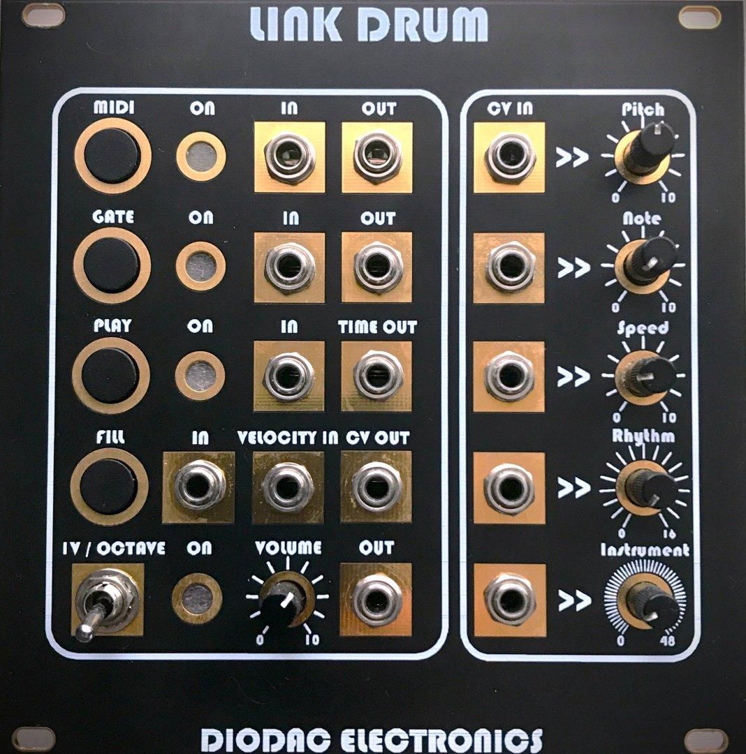
Link_Drum — DIY groovebox firmware & panel build
DIODAC Link_Drum: Atmega 328 / AT89C52 firmware, Rev 1.1 Gerbers, panel DXF, and BOM. MIT assets in diodac_audio.
MIT · hardware + firmware diodac_audio
GitHub folder diodac_audio repo DrDiodac
Intro
Link_Drum lives in the public MIT diodac_audio repository. Follow the repo filenames exactly — hardware paths keep spaces and original CAD names on purpose.
Safety: Mains-derived supplies and MIDI gear need care. Flash only after you understand the pin map in the user manual PDF.
Supplies
- Arduino IDE (Atmega 328 path) or suitable AT89C52 programmer
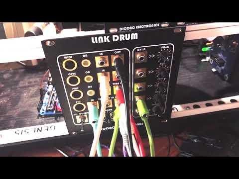
- Link_Drum hardware / PCB (Rev 1.1 Gerbers in repo)
- USB-serial programmer for the MCU you flash
- MIDI interface or synth to hear notes
- Optional: panel fabrication from DXF / Gerber panel folders
Clone Diodac_audio and Open Link_Drum
Keep folder names with spaces (e.g. Atmega 328) — they are intentional.
Step 2 Review manufacturing assets
Inspect Link_Drum REV.1.1_PCB/ (CPU + panel Gerbers), Circuit_Diagrams/ PDFs, and Link_Drum_Panel/ DXF before ordering boards.
Step 3 Flash Atmega 328 firmware (Rev 1.01)
Open Link_Drum_Code/Atmega 328/Link_Drum_Rev_1.01/Link_Drum_Rev_1.01.ino in Arduino IDE. Select the correct board/port and upload.
Maintenance notes in README: BPM timing, rest code EY (128), PROGMEM byte reads, note-off on stop.
Step 4 Optional AT89C52 HEX path
If your build uses the classic MCU, flash Link_Drum_Code/AT89C52/808.hex with your programmer. Do not mix pin assumptions with the Atmega sketch.
Step 5 Test after flash
Follow TEST_AFTER_FLASH.md — Link_Drum section. Minimum: transport start/stop, BPM timing, rest steps, no stuck MIDI notes.
Conclusion
Flash, run the minimum tests in TEST_AFTER_FLASH.md, then iterate. More DIODAC builds: DrDiodac.
https://github.com/iSystemDevelopment/diodac_audio/tree/main/Link_Drum
This project
Parent repo
Hub
© 2026 DIODAC ELECTRONICS / iSystem Development · MIT lab/hardware assets as published in repo