LinkIt One Tutorials - #10 Burglar Alarm
by gregoryfenton in Circuits > Microcontrollers
990 Views, 5 Favorites, 0 Comments
LinkIt One Tutorials - #10 Burglar Alarm

For this tutorial we are going to use a PIR (passive infra red) detector and a piezo buzzer to make a basic alarm system.
This is by no means capable of providing any real security but it is a great starting point for a real system.
Materials Required


LinkIt One board
Micro USB cable
Male to female jumper wires
Male to male jumper wires
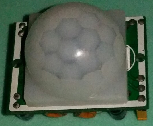
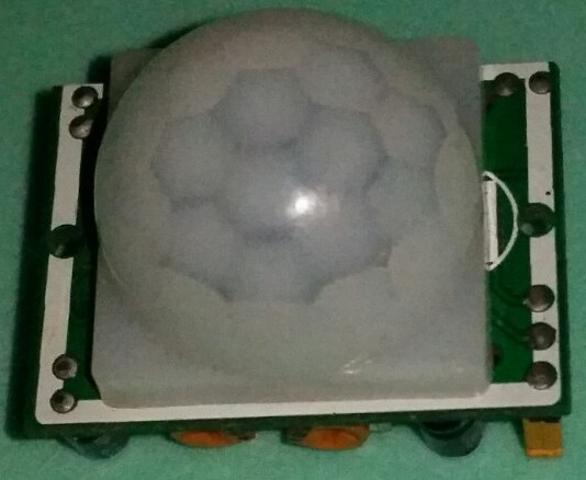
PIR detector
Search online for Arduino HC-SR501 and you should find many suppliers
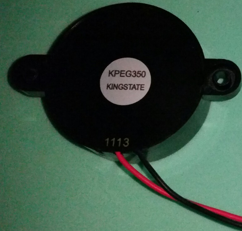
Piezo buzzer
Search online for KPEG350 or KPEG-350
Pushbutton
LED
1KOhm resistor
Program the LinkIt One With the BurglarAlarm.ino Sketch

Start the Arduino IDE.
Download the attached sketch file BurglarAlarm.ino and upload it to your LinkIt One board.
Downloads
Connect the Parts to the LinkIt One


Warning: this is a fair few jumper wires. Take it step by step and check your work very carefully.
For this tutorial we are going to use multiple devices which all require power or ground connections so we are going to use a breadboard properly and learn about the power rails.
If you look at your breadboard you will see that on either edge of the board is a red and blue line, broken in the middle.
These are the power rails and all the pins in a solid red strip are tied together, as are the pins in a solid blue strip.
The pins are not connected where there is a break in the line, nor are they connected from one edge to the other.
A standard breadboard will have 4 blue lines and 4 red lines. That means in theory you could have 4 different supply voltages and ground for each of them, or you could imagine that the breadboard is broken into 4 smaller breadboards, each a quarter of the size of the actual breadboard.
We are going to take advantage of these rails by just using one power line and one ground line.
We will now build up each part in turn.
Part 1: The pushbutton
Insert the pushbutton into the breadboard as in my previous tutorials. I have put one leg in column 18 and the other leg in column 20.
Take a jumper wire and connect column 18 to the ground (blue) rail.
Take another jumper wire and connect column 20 to pin D2 on the LinkIt One.
Part 2: The Piezoelectric buzzer
This has 2 connections, power (red) and ground (black).
Connect black to the ground rail (the blue bar)
Connect red to column 25 (picked at random so feel free to use another as long as you keep track).
Connect a male to male jumper wire from column 25 to D3 on the LinkIt One. I used brown.
Part 3: The PIR detector
This has 3 connections, ensure you know which pin goes where.
On mine pin 1 is VCC, pin 2 is signal and pin 3 is ground.
Take one of the female to male jumper wires (red) and connect the female end to the pin marked Vcc or V on the sensor.
Insert the male end of the jumper wire (red) into the red power rail on the breadboard.
Take one of the female to male jumper wires (black) and connect the female end to the pin marked gnd on the sensor.
Insert the male end of the jumper wire (black) into the blue power rail on the breadboard.
Take another female to male jumper wire (yellow) and connect the female end to the pin marked signal or out on the sensor.
Insert the male end of the yellow jumper wire into column 15 of the breadboard.
Take a male to male jumper wire (yellow) and insert one end into column 15 of the breadboard. There should now be 2 yellow wires plugged into column 15.
Take the other end of the yellow male to male jumper wire and insert it into A0 on the LinkIt One.
Part 4: Add a PIR triggered LED
Take the LED and plug the long leg (anode) into column 5 of the breadboard.
Plug the short leg (cathode) into the ground (blue) rail of the breadboard.
Plug one end of the resistor into column 5 of the breadboard.
Plug the other end of the resistor into column 1 of the breadboard.
Plug one end of a male to male jumper wire (purple) into column 1 of the breadboard.
Plug the other end of the purple jumper wire into port D4 of the LinkIt One.
Part 5: Connect the power and ground from the LinkIt One to the breadboard
Connect a red male to male jumper wire into 3v3 on the LinkIt One. Plug the other end into the power (red) rail of the breadboard.
Connect a black male to male jumper wire into GND on the LinkIt One. Plug the other end into the ground (blue) rail of the breadboard.
I reiterate, take each section steadily and recheck your work.
Connect the micro USB lead and look at the onboard LED. If it is lit the alarm is active.
Pressing the pushbutton will toggle the alarm on or off.
Move in front of the sensor and it will trigger the alarm if the LED is lit. You may want to cover the piezo buzzer hole as it is rather loud.
Where Next?

This can be massively expanded on to give almost total home protection.
Multiple sensors, door and window monitoring, keypad alarm codes, LCD display, SMS/email on trigger.
When we start getting multiple devices on one breadboard maybe it is time to progress onto PCB manufacture rather than relying on less than perfect wires.