LinkIt One Tutorials - #9 Joystick Control
by gregoryfenton in Circuits > Microcontrollers
624 Views, 9 Favorites, 0 Comments
LinkIt One Tutorials - #9 Joystick Control

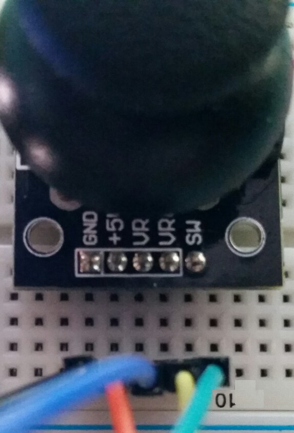

In this tutorial we will be interfacing to an analogue joystick and using the positional data to change the colour of our Grove LCD RBG Backlight display, as well as outputting the positions and button status to the LCD display.
This gives us the framework for joystick control of any program or even the hardware side of a game engine.
Materials Required


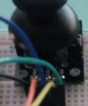

LinkIt One board
Micro USB cable
Arduino compatible analog joystick
Try your favourite auction site. Maybe vary the spelling to analogue. They are remarkably cheap.
Breadboard
5 jumper wires (black, red, yellow, green and blue)
Arduino IDE
Program the LinkIt One Board With the Joystick.ino Sketch
Download the attached file joystick.ino and load it into the Arduino IDE.
Upload the sketch to the LinkIt One board.
Disconnect everything from the LinkIt One, starting with the USB once the upload is complete.
Downloads
Connect the Parts to the LinkIt One

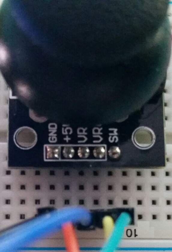
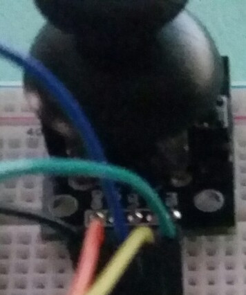
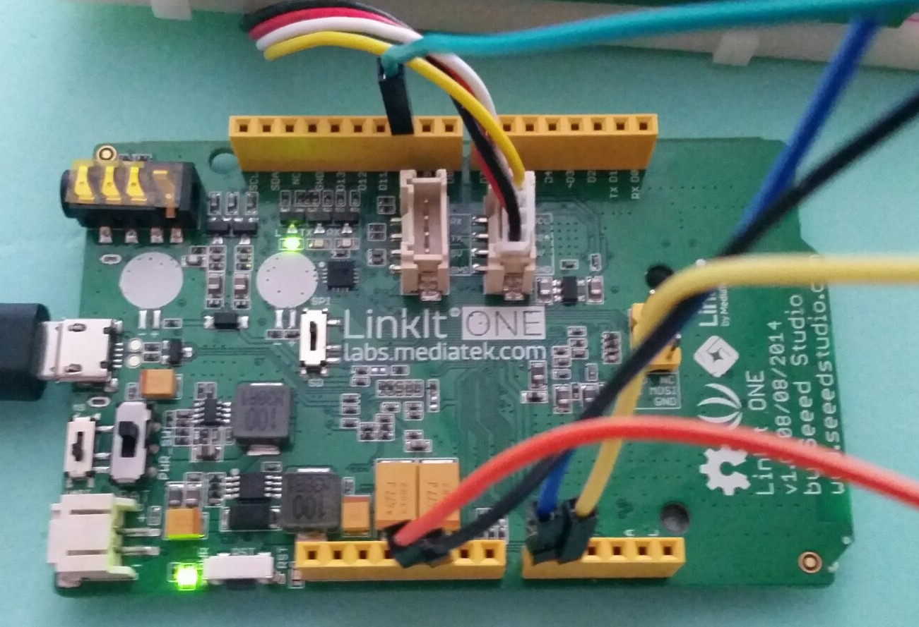

Disconnect everything from the LinkIt One board.
Insert the pins of the joystick into the breadboard with each pin in a separate column.
I will use columns 10 to 14 in my example.
If your joystick has pins that are parallel with the board so that should you plug it in the joystick is at 90 degrees to the breadboard you can either carefully bend the pins to be vertical or use male to female jumper leads.
The pins on the joystick should be
GND
5V
VRX
VRY
SW
If yours are labelled differently you need to figure out which pin corresponds to which label.
GND may be Ground, 0v, Vee, Vss
5V may be Vdd, Vcc, +V
VRX should have an X and is the X axis
VRY should have a Y and is the Y axis
SW may be labelled as S, B0, BUT.
If you have more than 5 pins then let me know the labels in the comments section and I will do my best to help you figure it out.
My breadboard has the following connections:
GND in 10
5V in 11
VRX in 12
VRY in 13
SW in 14
Connect the
Black jumper wire to GND on the LinkIt One and column 10
Red jumper wire to 5V on the LinkIt One and column 11
Blue jumper wire to A0 on the LinkIt One and column 12
Yellow jumper wire to A1 on the LinkIt One and column 13
Green jumper wire to D10 on the LinkIt One and column 14
Check and double check your wiring.
Connect the Grove LCD RGB Backlight to the Grove port on the LinkIt One with SCL and SDA.
Connect the USB cable to the LinkIt One.
Once the LinkIt One boots the LCD should turn on and be a dull yellow colour.
The X and Y have 4 numbers after them.
This is the position of the joystick from 0 (fully to one side) to 1023 (fully to the other side).
When the joystick is not being touched the numbers should both be somewhere close to 512.
SW has 1 number after it.
This is either 0 to signify the switch is not pressed or 1 to signify the switch is pressed.
Where Next?


We now have a way of controlling the LinkIt One.
We could use this to program games or control a running program.
Again, imagination is your limit. Explore the possibilities.
Don't forget to leave a comment with ideas for projects using joystick control.
Until the next tutorial